Sample Preparation and Soil Testing: Proctor, Modulus & Deformation
VerifiedAdded on 2023/06/11
|15
|2895
|384
Practical Assignment
AI Summary
This assignment provides a detailed overview of soil sample preparation and testing methods relevant to civil engineering. It covers the theory, scope, and procedures for preparing soil samples for tests such as the Proctor test, Resilient Modulus test, Permanent Deformation test, and Lime Demand test. The document includes definitions of key terms like bulk density, dry density, wet density, and optimum moisture content. It also details the apparatus and step-by-step procedures for compaction, permanent deformation, and resilient modulus tests, with data and calculations included. Soil samples are prepared from the Monash Highway construction site, with variations in moisture content to study the impact on compaction and other soil properties. Desklib offers a wealth of resources, including past papers and solved assignments, to support students in mastering these essential concepts and techniques.
SAMPLE PREPARATION
Theory
Scope: Before conducting any test, preparation of the sample is the most
important step and should be conducted first. It incorporates sieving, mixing,
compacting and conditioning of the materials processes. This step also includes
making the sample prepared before going to the tests like Proctor test, Resilient
Modulus test, Permanent Deformation test and Lime Demand test.
Definition:
Sample: Sample prepared of soil is submitted for testing to laboratory.
Bulk density: It is defined as the ratio of mass of a material to its volume. Mass
of the material includes solid particles, dust particles, water and air voids.
Dry density: It is defined as the ratio of mass to volume of. To calculate the dry
density of the material undried material after drying to constant mass at 105ºC to
110ºC is used.
Wet density: It is defined as the ratio of mass of a material to its volume of
undried material.
Moisture content: It is expressed in terms of percentage of dry mass, and can
be defined as the mass of water that can be extracted from the soil, by drying to
constant mass at 105ºC to 110ºC.
Optimum moisture content: It can be defined as the optimum soil moisture
content which produces maximum dry unit weight for a particular amount and its
type.
It is mandatory to use the distilled water while conducting test with soil.
Paraphrase This Document
Need a fresh take? Get an instant paraphrase of this document with our AI Paraphraser
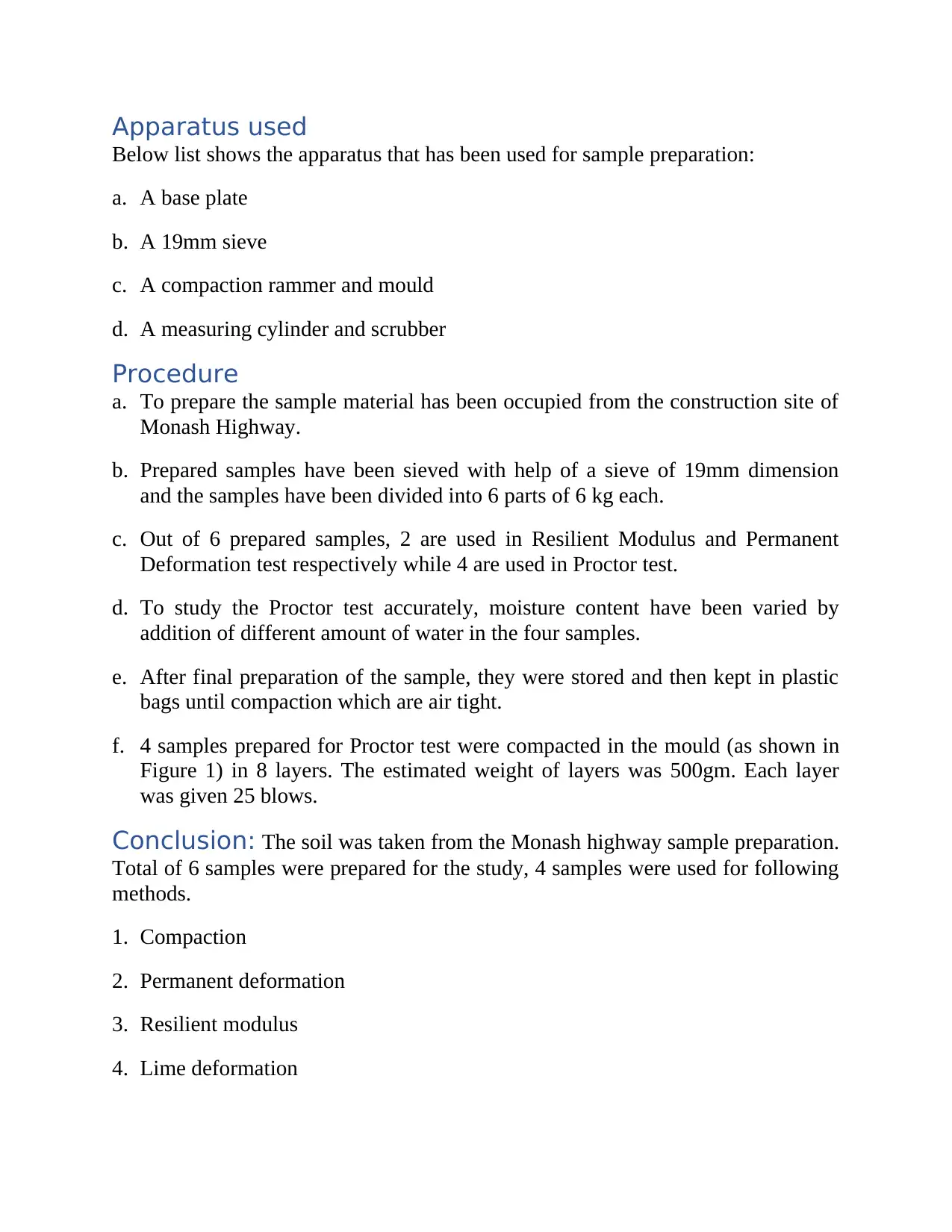
Apparatus used
Below list shows the apparatus that has been used for sample preparation:
a. A base plate
b. A 19mm sieve
c. A compaction rammer and mould
d. A measuring cylinder and scrubber
Procedure
a. To prepare the sample material has been occupied from the construction site of
Monash Highway.
b. Prepared samples have been sieved with help of a sieve of 19mm dimension
and the samples have been divided into 6 parts of 6 kg each.
c. Out of 6 prepared samples, 2 are used in Resilient Modulus and Permanent
Deformation test respectively while 4 are used in Proctor test.
d. To study the Proctor test accurately, moisture content have been varied by
addition of different amount of water in the four samples.
e. After final preparation of the sample, they were stored and then kept in plastic
bags until compaction which are air tight.
f. 4 samples prepared for Proctor test were compacted in the mould (as shown in
Figure 1) in 8 layers. The estimated weight of layers was 500gm. Each layer
was given 25 blows.
Conclusion: The soil was taken from the Monash highway sample preparation.
Total of 6 samples were prepared for the study, 4 samples were used for following
methods.
1. Compaction
2. Permanent deformation
3. Resilient modulus
4. Lime deformation
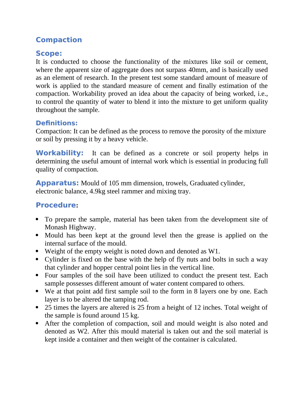
Compaction
Scope:
It is conducted to choose the functionality of the mixtures like soil or cement,
where the apparent size of aggregate does not surpass 40mm, and is basically used
as an element of research. In the present test some standard amount of measure of
work is applied to the standard measure of cement and finally estimation of the
compaction. Workability proved an idea about the capacity of being worked, i.e.,
to control the quantity of water to blend it into the mixture to get uniform quality
throughout the sample.
Definitions:
Compaction: It can be defined as the process to remove the porosity of the mixture
or soil by pressing it by a heavy vehicle.
Workability: It can be defined as a concrete or soil property helps in
determining the useful amount of internal work which is essential in producing full
quality of compaction.
Apparatus: Mould of 105 mm dimension, trowels, Graduated cylinder,
electronic balance, 4.9kg steel rammer and mixing tray.
Procedure:
To prepare the sample, material has been taken from the development site of
Monash Highway.
Mould has been kept at the ground level then the grease is applied on the
internal surface of the mould.
Weight of the empty weight is noted down and denoted as W1.
Cylinder is fixed on the base with the help of fly nuts and bolts in such a way
that cylinder and hopper central point lies in the vertical line.
Four samples of the soil have been utilized to conduct the present test. Each
sample possesses different amount of water content compared to others.
We at that point add first sample soil to the form in 8 layers one by one. Each
layer is to be altered the tamping rod.
25 times the layers are altered is 25 from a height of 12 inches. Total weight of
the sample is found around 15 kg.
After the completion of compaction, soil and mould weight is also noted and
denoted as W2. After this mould material is taken out and the soil material is
kept inside a container and then weight of the container is calculated.
⊘ This is a preview!⊘
Do you want full access?
Subscribe today to unlock all pages.
Trusted by 1+ million students worldwide
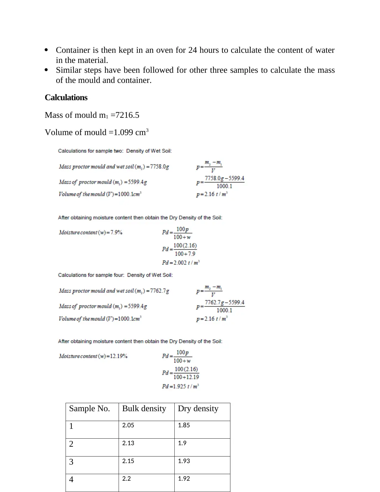
Container is then kept in an oven for 24 hours to calculate the content of water
in the material.
Similar steps have been followed for other three samples to calculate the mass
of the mould and container.
Calculations
Mass of mould m1 =7216.5
Volume of mould =1.099 cm3
Sample No. Bulk density Dry density
1 2.05 1.85
2 2.13 1.9
3 2.15 1.93
4 2.2 1.92
in the material.
Similar steps have been followed for other three samples to calculate the mass
of the mould and container.
Calculations
Mass of mould m1 =7216.5
Volume of mould =1.099 cm3
Sample No. Bulk density Dry density
1 2.05 1.85
2 2.13 1.9
3 2.15 1.93
4 2.2 1.92
Paraphrase This Document
Need a fresh take? Get an instant paraphrase of this document with our AI Paraphraser
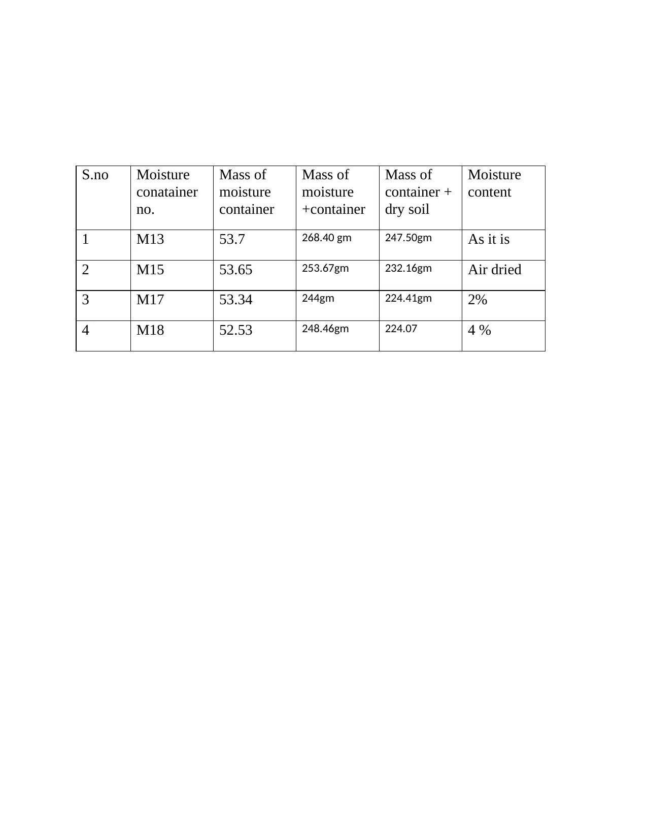
S.no Moisture
conatainer
no.
Mass of
moisture
container
Mass of
moisture
+container
Mass of
container +
dry soil
Moisture
content
1 M13 53.7 268.40 gm 247.50gm As it is
2 M15 53.65 253.67gm 232.16gm Air dried
3 M17 53.34 244gm 224.41gm 2%
4 M18 52.53 248.46gm 224.07 4 %
conatainer
no.
Mass of
moisture
container
Mass of
moisture
+container
Mass of
container +
dry soil
Moisture
content
1 M13 53.7 268.40 gm 247.50gm As it is
2 M15 53.65 253.67gm 232.16gm Air dried
3 M17 53.34 244gm 224.41gm 2%
4 M18 52.53 248.46gm 224.07 4 %
0.5 1 1.5 2 2.5 3 3.5 4 4.5
1.8
1.82
1.84
1.86
1.88
1.9
1.92
1.94
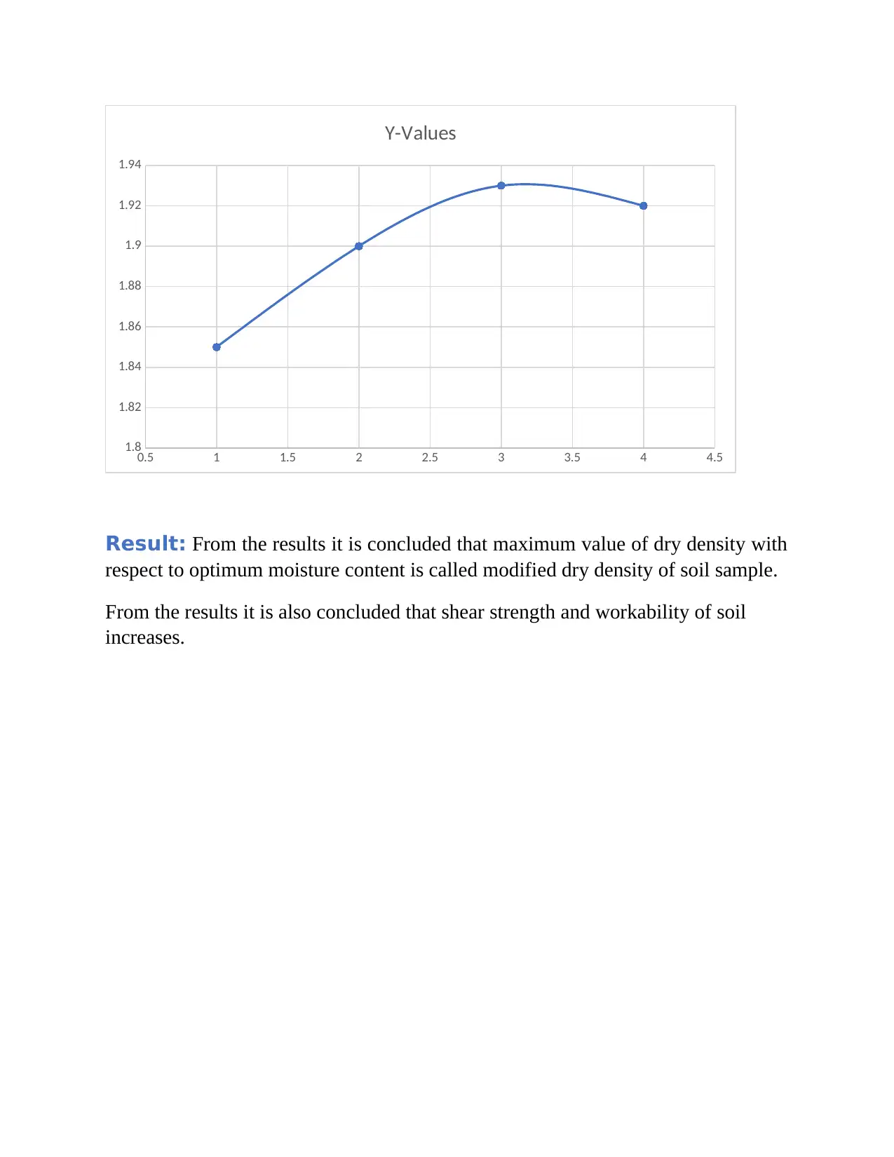
Y-Values
Result: From the results it is concluded that maximum value of dry density with
respect to optimum moisture content is called modified dry density of soil sample.
From the results it is also concluded that shear strength and workability of soil
increases.
1.8
1.82
1.84
1.86
1.88
1.9
1.92
1.94
Y-Values
Result: From the results it is concluded that maximum value of dry density with
respect to optimum moisture content is called modified dry density of soil sample.
From the results it is also concluded that shear strength and workability of soil
increases.
⊘ This is a preview!⊘
Do you want full access?
Subscribe today to unlock all pages.
Trusted by 1+ million students worldwide
Permanent Deformation
Scope: Permanent deformation test shows astounding means to differentiate the
developed materials under an arrangement of conditions the condition like
dampness, degree and stretch states. The unchanging distortion affirmation depicts
the vertical enduring through 3 conditions of stress using 3 levels vertical stresses
and one static lateral stress. Every situation includes 10,000 iteration of vertical
stress. In light of the test results, stretch ward traits of both enduring strain for the
illustration can be solved.
Definition:
Fleeting shape change that is self-exchanging after the compel is cleared, with the
goal that the inquiry returns to its original shape, is called versatile misshaping.
Toward the day's end, flexibility deformation is a change and well of a material at
low tension that is recoverable after the anxiety is evacuated.
Vertical stress: After the application of pressure on rock or soil with on the
vertical direction with weight is called vertical stress.
Lateral strain: Lateral strain can be defines as the diameter change to length
change in the longitudinal direction when load is applied.
Apparatus:
105 mm compaction mould, trowels, Graduated cylinder, electronic balance, 4.9kg
steel rammer and mixing tray.
Procedure:
To prepare the sample, material has been taken from the development site of
Monash Highway.
Mould has been kept at the ground level then the grease is applied on the
internal surface of the mould.
Weight of the empty weight is noted down and denoted as W1.
Cylinder is fixed on the base with the help of fly nuts and bolts in such a way
that cylinder and hopper central point lies in the vertical line.
We at that point add first sample soil to the form in 8 layers one by one. Each
layer is to be altered the tamping rod.
Each layer is gone through 25 numbers of blows by the 15 kg tamping rod.
When the process of compaction is completed, weight of the mould and soil is
taken and noted as W2.
Paraphrase This Document
Need a fresh take? Get an instant paraphrase of this document with our AI Paraphraser
After this removal of the material from the mould is done carefully considering
that it does not break.
This compacted material is then placed inside a rubber tube fitted to the jar.
To stop the entering of the water a porous stone is fitted on the top and bottom.
Rubber stopper also used to close it to ensure no leaking of entering and of
water when placed in triaxial cell.
The material is then placed inside the cell ensuring it exactly fit at the center
and below the load cap.
The rigid cell is then placed and tightening of the pins is also ensured. The
water is then allows to flow inside the jar. The jar is filled fully ensuring no air
in the jar is left.
Now allow load factor to apply on the material.
In consecutive request, for every one of the three stress stages chosen, apply
and hold the static confining pressure to the sample, at that point apply cycles of
loading and emptying of the separate repeated vertical stress for 10,000
iterations.
Calculation
Result
conclusion
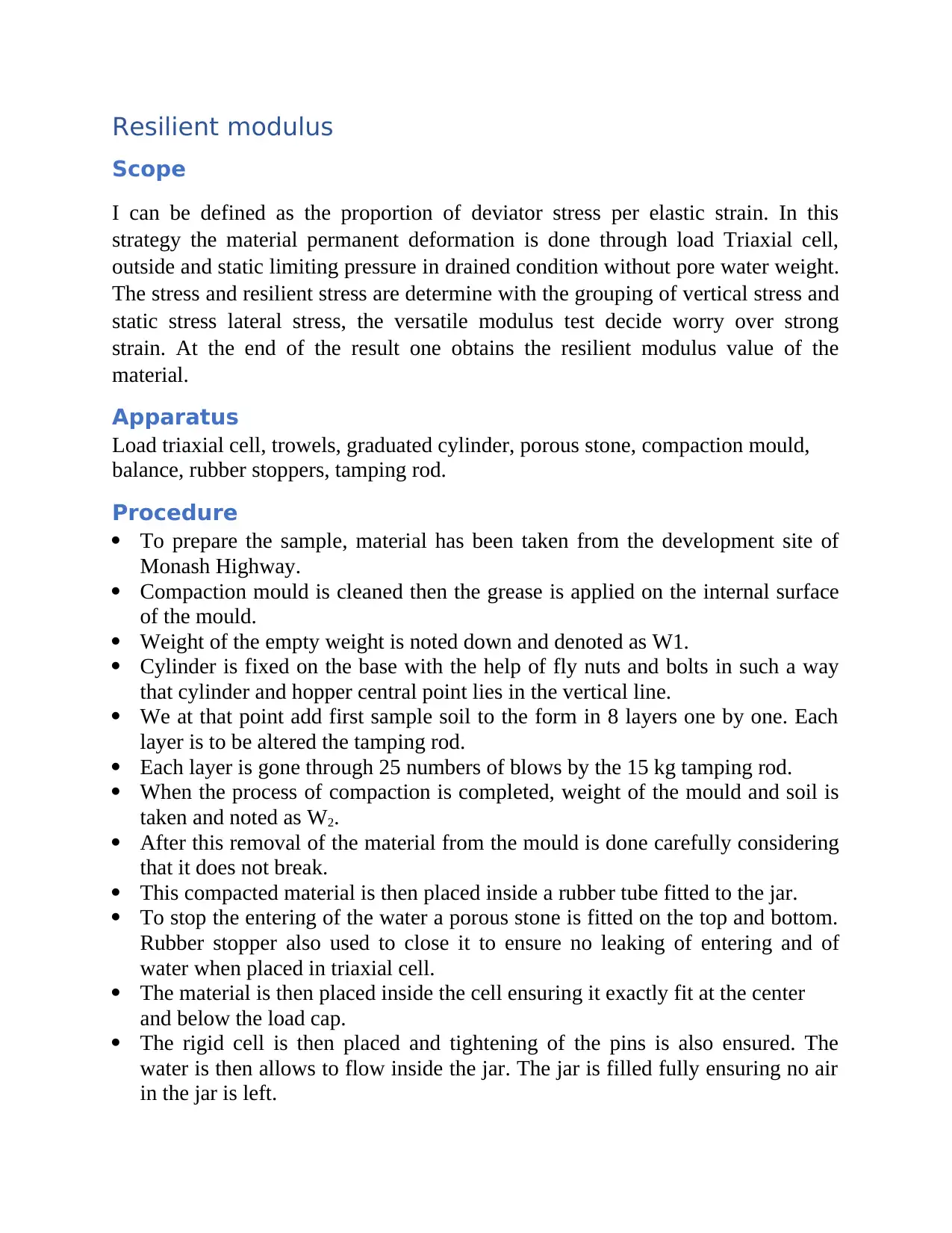
Resilient modulus
Scope
I can be defined as the proportion of deviator stress per elastic strain. In this
strategy the material permanent deformation is done through load Triaxial cell,
outside and static limiting pressure in drained condition without pore water weight.
The stress and resilient stress are determine with the grouping of vertical stress and
static stress lateral stress, the versatile modulus test decide worry over strong
strain. At the end of the result one obtains the resilient modulus value of the
material.
Apparatus
Load triaxial cell, trowels, graduated cylinder, porous stone, compaction mould,
balance, rubber stoppers, tamping rod.
Procedure
To prepare the sample, material has been taken from the development site of
Monash Highway.
Compaction mould is cleaned then the grease is applied on the internal surface
of the mould.
Weight of the empty weight is noted down and denoted as W1.
Cylinder is fixed on the base with the help of fly nuts and bolts in such a way
that cylinder and hopper central point lies in the vertical line.
We at that point add first sample soil to the form in 8 layers one by one. Each
layer is to be altered the tamping rod.
Each layer is gone through 25 numbers of blows by the 15 kg tamping rod.
When the process of compaction is completed, weight of the mould and soil is
taken and noted as W2.
After this removal of the material from the mould is done carefully considering
that it does not break.
This compacted material is then placed inside a rubber tube fitted to the jar.
To stop the entering of the water a porous stone is fitted on the top and bottom.
Rubber stopper also used to close it to ensure no leaking of entering and of
water when placed in triaxial cell.
The material is then placed inside the cell ensuring it exactly fit at the center
and below the load cap.
The rigid cell is then placed and tightening of the pins is also ensured. The
water is then allows to flow inside the jar. The jar is filled fully ensuring no air
in the jar is left.
⊘ This is a preview!⊘
Do you want full access?
Subscribe today to unlock all pages.
Trusted by 1+ million students worldwide
Permit load factor to apply on the material with vertical resilient strain reaction
more than 66 stress conditions utilizing combination of applied repeated static
lateral stress and vertical stress.
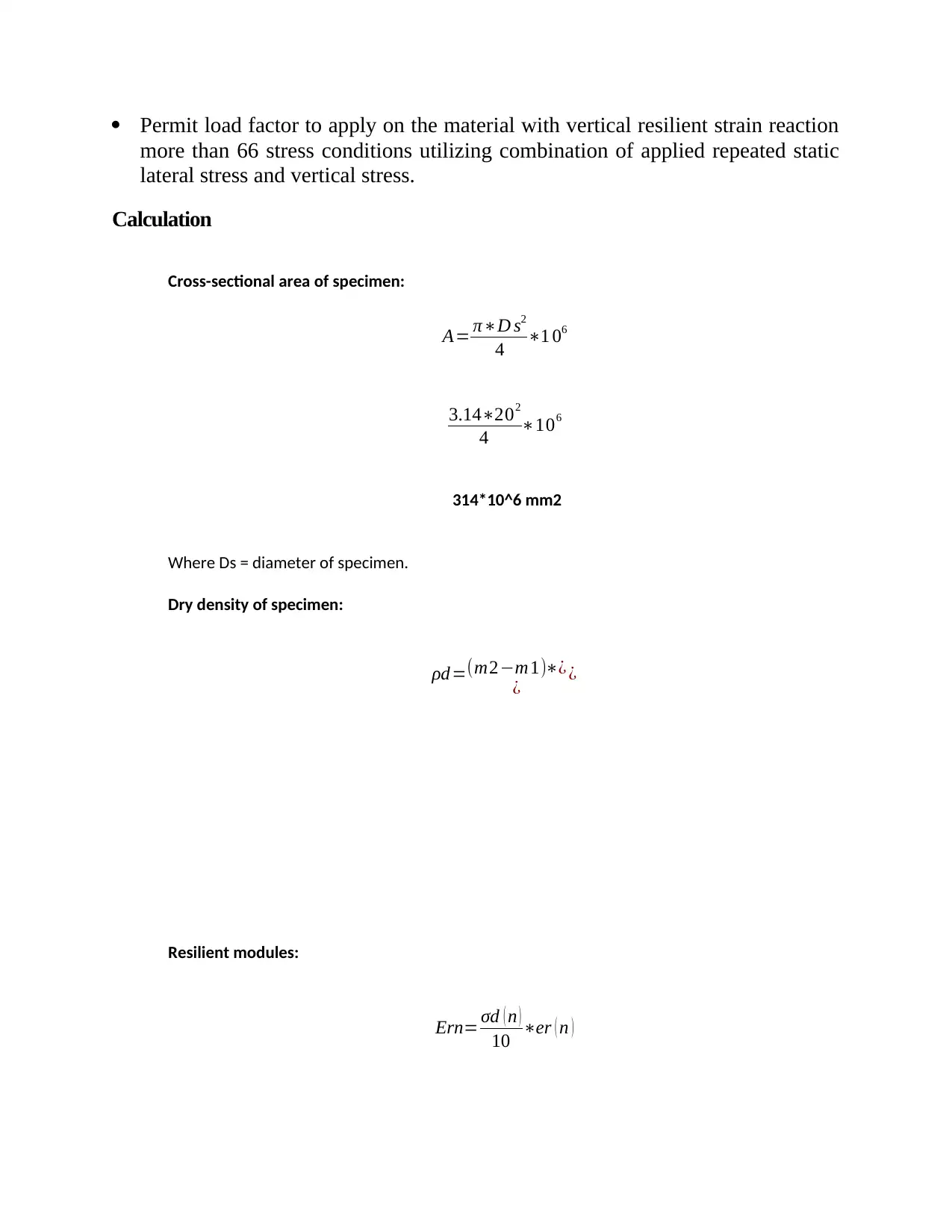
Calculation
Cross-sectional area of specimen:
A= π∗D s2
4 ∗1 06
3.14∗202
4 ∗106
314*10^6 mm2
Where Ds = diameter of specimen.
Dry density of specimen:
ρd=(m2−m1)∗¿
¿ ¿
Resilient modules:
Ern= σd ( n )
10 ∗er ( n )
more than 66 stress conditions utilizing combination of applied repeated static
lateral stress and vertical stress.
Calculation
Cross-sectional area of specimen:
A= π∗D s2
4 ∗1 06
3.14∗202
4 ∗106
314*10^6 mm2
Where Ds = diameter of specimen.
Dry density of specimen:
ρd=(m2−m1)∗¿
¿ ¿
Resilient modules:
Ern= σd ( n )
10 ∗er ( n )
Paraphrase This Document
Need a fresh take? Get an instant paraphrase of this document with our AI Paraphraser

Result
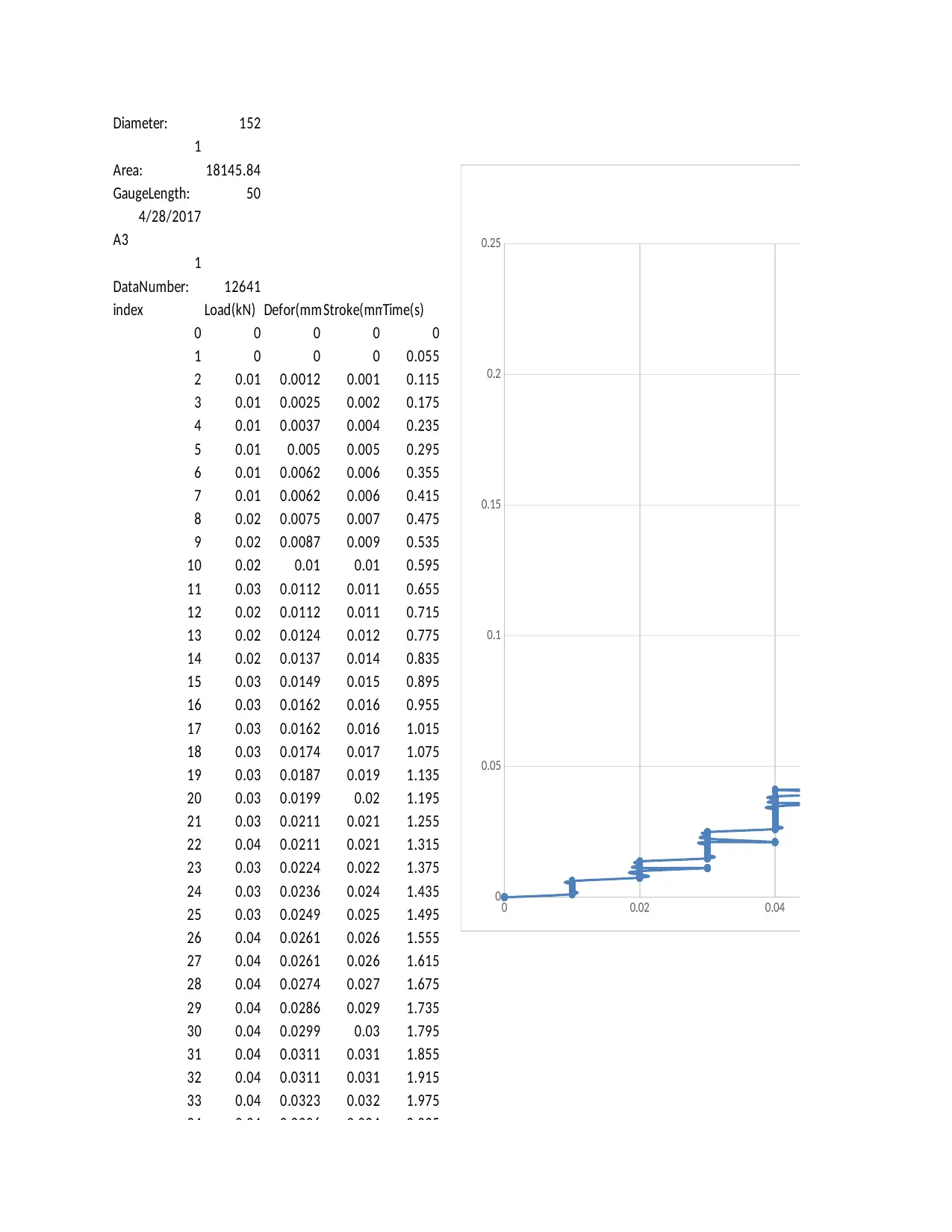
Diameter: 152
1
Area: 18145.84
GaugeLength: 50
4/28/2017
A3
1
DataNumber: 12641
index Load(kN) Defor(mm)Stroke(mmTime(s)
0 0 0 0 0
1 0 0 0 0.055
2 0.01 0.0012 0.001 0.115
3 0.01 0.0025 0.002 0.175
4 0.01 0.0037 0.004 0.235
5 0.01 0.005 0.005 0.295
6 0.01 0.0062 0.006 0.355
7 0.01 0.0062 0.006 0.415
8 0.02 0.0075 0.007 0.475
9 0.02 0.0087 0.009 0.535
10 0.02 0.01 0.01 0.595
11 0.03 0.0112 0.011 0.655
12 0.02 0.0112 0.011 0.715
13 0.02 0.0124 0.012 0.775
14 0.02 0.0137 0.014 0.835
15 0.03 0.0149 0.015 0.895
16 0.03 0.0162 0.016 0.955
17 0.03 0.0162 0.016 1.015
18 0.03 0.0174 0.017 1.075
19 0.03 0.0187 0.019 1.135
20 0.03 0.0199 0.02 1.195
21 0.03 0.0211 0.021 1.255
22 0.04 0.0211 0.021 1.315
23 0.03 0.0224 0.022 1.375
24 0.03 0.0236 0.024 1.435
25 0.03 0.0249 0.025 1.495
26 0.04 0.0261 0.026 1.555
27 0.04 0.0261 0.026 1.615
28 0.04 0.0274 0.027 1.675
29 0.04 0.0286 0.029 1.735
30 0.04 0.0299 0.03 1.795
31 0.04 0.0311 0.031 1.855
32 0.04 0.0311 0.031 1.915
33 0.04 0.0323 0.032 1.975
34 0.04 0.0336 0.034 2.035
35 0.04 0.0348 0.035 2.095
36 0.05 0.0361 0.036 2.155
37 0.04 0.0361 0.036 2.215
38 0.04 0.0373 0.037 2.275
0 0.02 0.04 0.06
0
0.05
0.1
0.15
0.2
0.25
Ch
1
Area: 18145.84
GaugeLength: 50
4/28/2017
A3
1
DataNumber: 12641
index Load(kN) Defor(mm)Stroke(mmTime(s)
0 0 0 0 0
1 0 0 0 0.055
2 0.01 0.0012 0.001 0.115
3 0.01 0.0025 0.002 0.175
4 0.01 0.0037 0.004 0.235
5 0.01 0.005 0.005 0.295
6 0.01 0.0062 0.006 0.355
7 0.01 0.0062 0.006 0.415
8 0.02 0.0075 0.007 0.475
9 0.02 0.0087 0.009 0.535
10 0.02 0.01 0.01 0.595
11 0.03 0.0112 0.011 0.655
12 0.02 0.0112 0.011 0.715
13 0.02 0.0124 0.012 0.775
14 0.02 0.0137 0.014 0.835
15 0.03 0.0149 0.015 0.895
16 0.03 0.0162 0.016 0.955
17 0.03 0.0162 0.016 1.015
18 0.03 0.0174 0.017 1.075
19 0.03 0.0187 0.019 1.135
20 0.03 0.0199 0.02 1.195
21 0.03 0.0211 0.021 1.255
22 0.04 0.0211 0.021 1.315
23 0.03 0.0224 0.022 1.375
24 0.03 0.0236 0.024 1.435
25 0.03 0.0249 0.025 1.495
26 0.04 0.0261 0.026 1.555
27 0.04 0.0261 0.026 1.615
28 0.04 0.0274 0.027 1.675
29 0.04 0.0286 0.029 1.735
30 0.04 0.0299 0.03 1.795
31 0.04 0.0311 0.031 1.855
32 0.04 0.0311 0.031 1.915
33 0.04 0.0323 0.032 1.975
34 0.04 0.0336 0.034 2.035
35 0.04 0.0348 0.035 2.095
36 0.05 0.0361 0.036 2.155
37 0.04 0.0361 0.036 2.215
38 0.04 0.0373 0.037 2.275
0 0.02 0.04 0.06
0
0.05
0.1
0.15
0.2
0.25
Ch
⊘ This is a preview!⊘
Do you want full access?
Subscribe today to unlock all pages.
Trusted by 1+ million students worldwide
1 out of 15
Related Documents


Your All-in-One AI-Powered Toolkit for Academic Success.
+13062052269
info@desklib.com
Available 24*7 on WhatsApp / Email
![[object Object]](/_next/static/media/star-bottom.7253800d.svg)
Unlock your academic potential
Copyright © 2020–2026 A2Z Services. All Rights Reserved. Developed and managed by ZUCOL.