Electrical Engineering Project: Solar Panel Functioning and Detection
VerifiedAdded on 2023/06/04
|24
|7685
|279
Project
AI Summary
This project report, authored by Vipul Kumar Mulkalapally under the guidance of Dr. Hamid Abdi, delves into the functioning and fault detection methods of photovoltaic (PV) panels. It begins with an introduction to the growing significance of solar energy and the environmental benefits it offers, highlighting the need for efficient and reliable solar panel systems. The report outlines the project's aim to analyze PV panel characteristics, identify potential faults, and explore monitoring and detection techniques. It includes a comprehensive literature review, the development of a solar panel model with I-V characteristics, and the analysis of short circuit and open circuit equations. The methodology section details the research strategy, which is based on existing literature and data analysis. The project addresses key challenges such as shading effects and explores the use of aerial thermal imaging, drone technology, and database analysis for fault detection in large-scale solar plants. Overall, the project aims to provide a detailed understanding of solar panel operation and the strategies for maintaining their performance and reliability.
Functioning and Detection of solar panels
Project Guide: Dr. Hamid Abdi
Student name: Vipul Kumar Mulkalapally
Student ID: 217244955
1
Project Guide: Dr. Hamid Abdi
Student name: Vipul Kumar Mulkalapally
Student ID: 217244955
1
Paraphrase This Document
Need a fresh take? Get an instant paraphrase of this document with our AI Paraphraser
Contents
1. Introduction:..............................................................................................................................4
2. Project Aim and Objective:.........................................................................................................5
1.1. Problem summary..............................................................................................................6
1.2. Research Strategy...............................................................................................................6
1.3. Solar Panel Model:.............................................................................................................6
1.4. Short circuit and open circuit equations:..........................................................................10
1.5. Size of Array:....................................................................................................................10
3. Literature Review.....................................................................................................................10
4. Detailed Methodology..............................................................................................................12
References........................................................................................................................................18
2

Figure 1 Solar movement summer and winter...................................................................................4
Figure 2 Solar cell modeling...............................................................................................................6
Figure 3 I-V characteristics.................................................................................................................7
Figure 4 Accurate PV modeling..........................................................................................................8
Figure 5 Loss spots of PV..................................................................................................................14
Figure 6 Machine learning basic flow chart......................................................................................15
Figure 7 Sensor and meters of Photovoltaic plant………………………………………………………………………..17
Figure 8 Project Gantt chart.............................................................................................................16
3
⊘ This is a preview!⊘
Do you want full access?
Subscribe today to unlock all pages.
Trusted by 1+ million students worldwide
1. Introduction:
As per the International Renewable Energy Agency (IRENA) solar installed capacity
worldwide is around 23 GW in 2018 which is 8 times higher from 2014, looking at the
figures the implementation and success of solar are the highest amount other existing
renewable energy sources. [1]. With the increase in population and the use of fuels as
primary energy source is increasing which add up the air pollution due to burning of fossil
fuel such as coal, and other, which increase the green house effect and global warming, the
use of such fuels needs to be minimized using alternate energy sources such as
photovoltaic, wind, fuel cell, tidal, geothermal, biogas, electric vehicles etc. Another issue
with fossil fuel is depleting at fast rate, conservation is needed to save or utilize such fuels
in important task or processes. The readily and easily available source is solar energy which
can be utilize in many applications using small setups such as solar collector for cooking
purpose, solar base water tube for water heating, use of solar for vehicles and solar panels
for electricity. However, the efficiency and the conversion rate is low for electricity use.
Small residential home requires to setup panel of at least 2kW for all time use with back of
battery which increase the overall cost of setup of solar for home use. One of the reasons
for least acceptance of solar is high cost of installation and maintenance requirement, how
ever cost of maintenance is less.
Figure 1 Solar movement summer and winter
Shading is the big issue with the photovoltaic system, it ultimately decreases the efficiency
and performance of the array and may also cause damage to arrays. Whenever subjected to
4
Paraphrase This Document
Need a fresh take? Get an instant paraphrase of this document with our AI Paraphraser
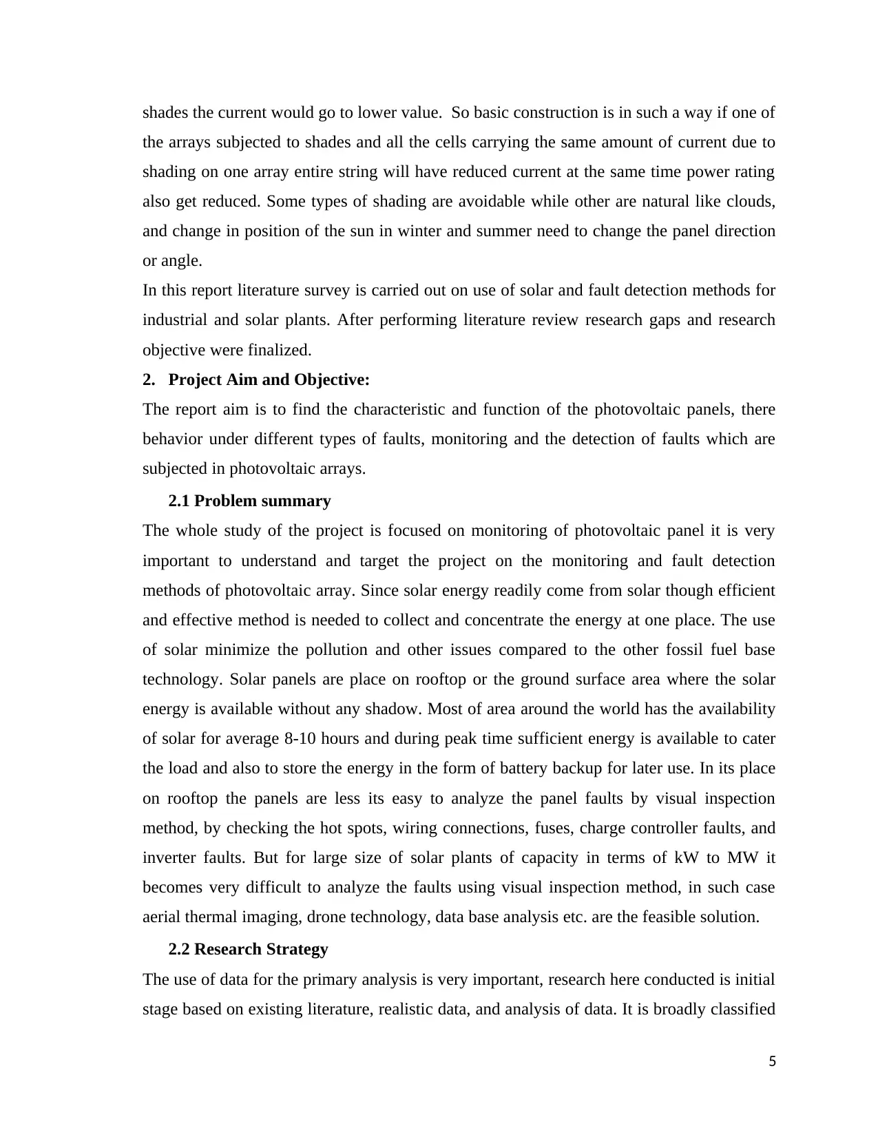
shades the current would go to lower value. So basic construction is in such a way if one of
the arrays subjected to shades and all the cells carrying the same amount of current due to
shading on one array entire string will have reduced current at the same time power rating
also get reduced. Some types of shading are avoidable while other are natural like clouds,
and change in position of the sun in winter and summer need to change the panel direction
or angle.
In this report literature survey is carried out on use of solar and fault detection methods for
industrial and solar plants. After performing literature review research gaps and research
objective were finalized.
2. Project Aim and Objective:
The report aim is to find the characteristic and function of the photovoltaic panels, there
behavior under different types of faults, monitoring and the detection of faults which are
subjected in photovoltaic arrays.
2.1 Problem summary
The whole study of the project is focused on monitoring of photovoltaic panel it is very
important to understand and target the project on the monitoring and fault detection
methods of photovoltaic array. Since solar energy readily come from solar though efficient
and effective method is needed to collect and concentrate the energy at one place. The use
of solar minimize the pollution and other issues compared to the other fossil fuel base
technology. Solar panels are place on rooftop or the ground surface area where the solar
energy is available without any shadow. Most of area around the world has the availability
of solar for average 8-10 hours and during peak time sufficient energy is available to cater
the load and also to store the energy in the form of battery backup for later use. In its place
on rooftop the panels are less its easy to analyze the panel faults by visual inspection
method, by checking the hot spots, wiring connections, fuses, charge controller faults, and
inverter faults. But for large size of solar plants of capacity in terms of kW to MW it
becomes very difficult to analyze the faults using visual inspection method, in such case
aerial thermal imaging, drone technology, data base analysis etc. are the feasible solution.
2.2 Research Strategy
The use of data for the primary analysis is very important, research here conducted is initial
stage based on existing literature, realistic data, and analysis of data. It is broadly classified
5
as qualitative research and quantitative research,
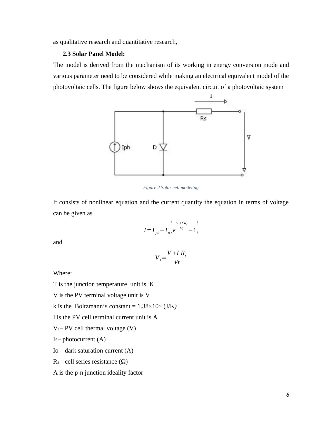
2.3 Solar Panel Model:
The model is derived from the mechanism of its working in energy conversion mode and
various parameter need to be considered while making an electrical equivalent model of the
photovoltaic cells. The figure below shows the equivalent circuit of a photovoltaic system
Figure 2 Solar cell modeling
It consists of nonlinear equation and the current quantity the equation in terms of voltage
can be given as
I =I ph−I o (e
V +I Rs
Vt −1 )
and
V t =V +I Rs
Vt
Where:
T is the junction temperature unit is K
V is the PV terminal voltage unit is V
k is the Boltzmann’s constant = 1.38×10⁻²³ (J/K)
I is the PV cell terminal current unit is A
Vt – PV cell thermal voltage (V)
If – photocurrent (A)
Io – dark saturation current (A)
Rs – cell series resistance (Ω)
A is the p-n junction ideality factor
6
⊘ This is a preview!⊘
Do you want full access?
Subscribe today to unlock all pages.
Trusted by 1+ million students worldwide
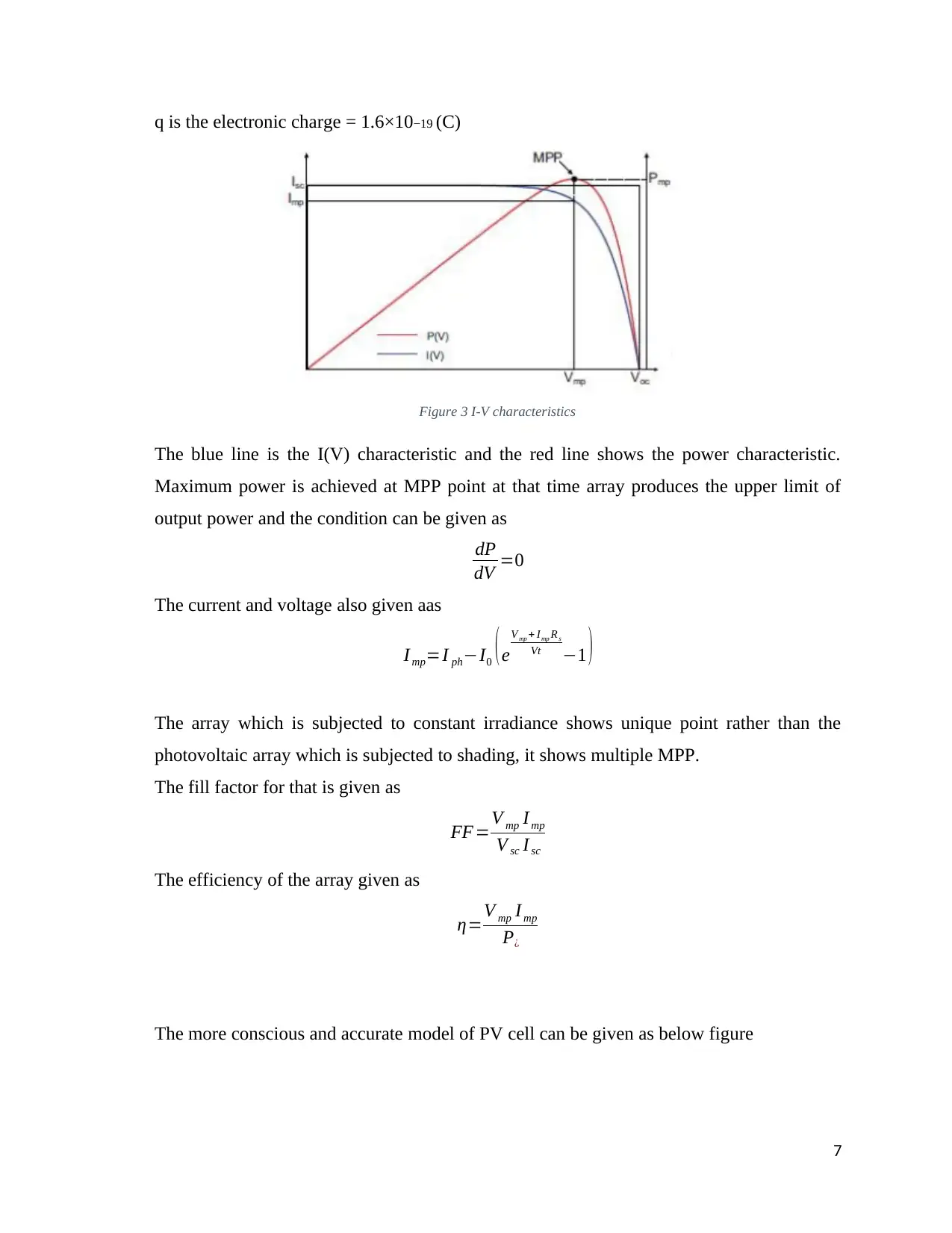
q is the electronic charge = 1.6×10⁻¹⁹ (C)
Figure 3 I-V characteristics
The blue line is the I(V) characteristic and the red line shows the power characteristic.
Maximum power is achieved at MPP point at that time array produces the upper limit of
output power and the condition can be given as
dP
dV =0
The current and voltage also given aas
I mp=I ph−I0 ( e
V mp + Imp R s
Vt −1 )
The array which is subjected to constant irradiance shows unique point rather than the
photovoltaic array which is subjected to shading, it shows multiple MPP.
The fill factor for that is given as
FF=V mp I mp
V sc I sc
The efficiency of the array given as
η=V mp I mp
P¿
The more conscious and accurate model of PV cell can be given as below figure
7
Paraphrase This Document
Need a fresh take? Get an instant paraphrase of this document with our AI Paraphraser
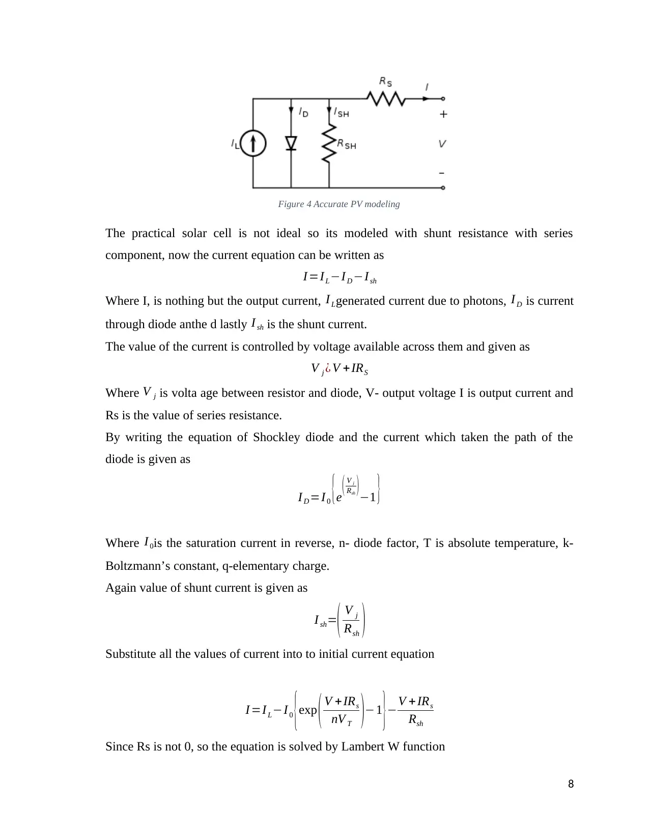
Figure 4 Accurate PV modeling
The practical solar cell is not ideal so its modeled with shunt resistance with series
component, now the current equation can be written as
I =I L−I D −Ish
Where I, is nothing but the output current, I Lgenerated current due to photons, I D is current
through diode anthe d lastly I sh is the shunt current.
The value of the current is controlled by voltage available across them and given as
V j ¿ V +IRS
Where V j is volta age between resistor and diode, V- output voltage I is output current and
Rs is the value of series resistance.
By writing the equation of Shockley diode and the current which taken the path of the
diode is given as
I D =I 0 {e ( V j
Rsh ) −1 }
Where I 0is the saturation current in reverse, n- diode factor, T is absolute temperature, k-
Boltzmann’s constant, q-elementary charge.
Again value of shunt current is given as
I sh=( V j
Rsh )
Substitute all the values of current into to initial current equation
I =I L−I 0 {exp ( V +IRs
nV T )−1
}−V +IRs
Rsh
Since Rs is not 0, so the equation is solved by Lambert W function
8
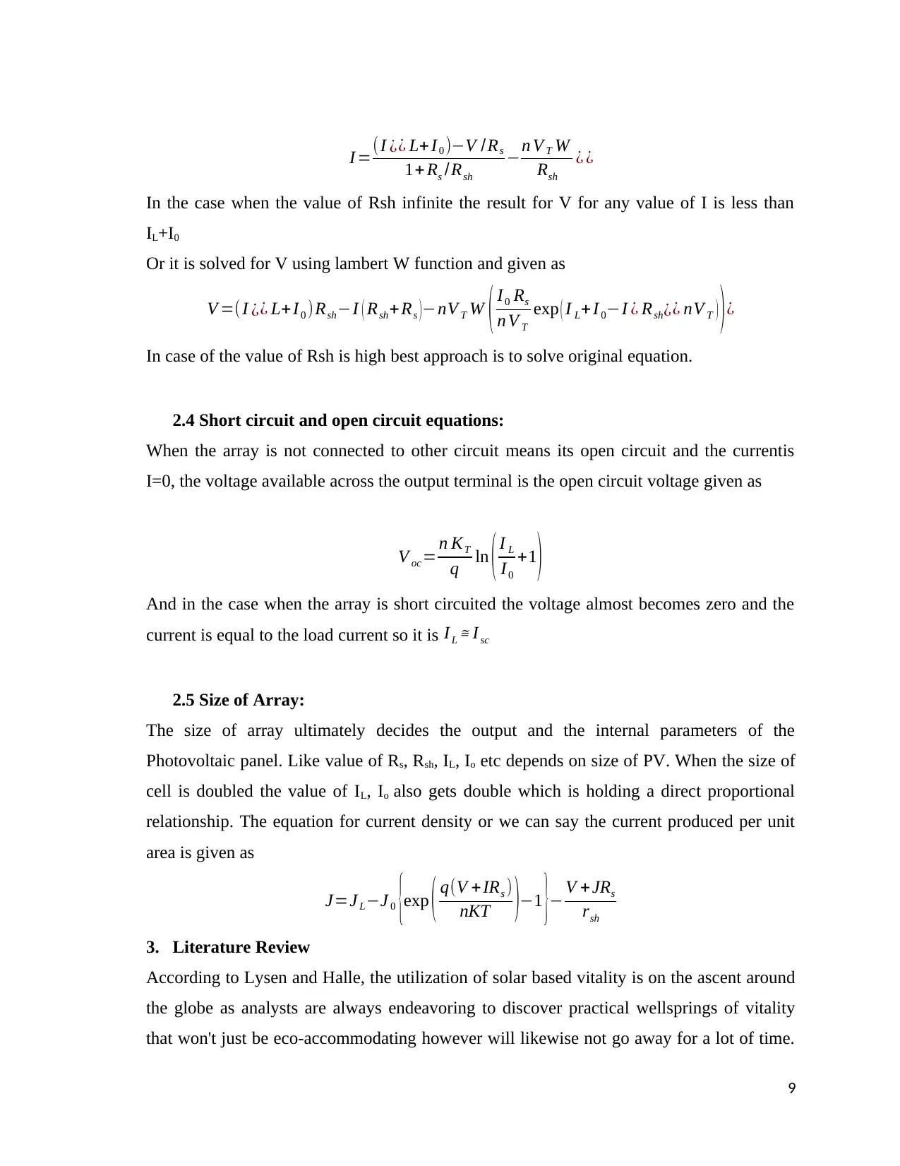
I =(I ¿¿ L+I 0 )−V /Rs
1+ Rs /Rsh
−n V T W
Rsh
¿ ¿
In the case when the value of Rsh infinite the result for V for any value of I is less than
IL+I0
Or it is solved for V using lambert W function and given as
V =( I ¿¿ L+I0 )Rsh−I ( Rsh+Rs )−nV T W ( I0 Rs
n V T
exp ( I L+ I 0−I ¿ Rsh¿¿ nV T ) )¿
In case of the value of Rsh is high best approach is to solve original equation.
2.4 Short circuit and open circuit equations:
When the array is not connected to other circuit means its open circuit and the currentis
I=0, the voltage available across the output terminal is the open circuit voltage given as
V oc= n KT
q ln ( I L
I 0
+1)
And in the case when the array is short circuited the voltage almost becomes zero and the
current is equal to the load current so it is I L ≅ I sc
2.5 Size of Array:
The size of array ultimately decides the output and the internal parameters of the
Photovoltaic panel. Like value of Rs, Rsh, IL, Io etc depends on size of PV. When the size of
cell is doubled the value of IL, Io also gets double which is holding a direct proportional
relationship. The equation for current density or we can say the current produced per unit
area is given as
J=J L−J 0 {exp ( q(V + IRs )
nKT )−1 }− V +JRs
rsh
3. Literature Review
According to Lysen and Halle, the utilization of solar based vitality is on the ascent around
the globe as analysts are always endeavoring to discover practical wellsprings of vitality
that won't just be eco-accommodating however will likewise not go away for a lot of time.
9
⊘ This is a preview!⊘
Do you want full access?
Subscribe today to unlock all pages.
Trusted by 1+ million students worldwide
With respect to the reasons, the specialists have expressed that the current wellsprings of
vitality incorporate coal, oil, oil, and others that have significant negative effects on nature.
This is primarily in light of the fact that the ignition of the petroleum derivatives makes a
tremendous measure of lethal gases that influences the adjacent creatures as well as the
general condition in general, causing an unnatural weather change. With the exponential
increment in the utilization of non-renewable energy sources broadly all through the planet,
the degree of contamination is likewise expanding step by step. Once more, the wellsprings
of these fills are restricted and are rapidly becoming scarce around the globe. It is normal
that inside the following couple of decades, the wellsprings of oil far and wide will become
scarce totally.
Kamat and Christians stated that the world needs another wellspring of vitality that won't
just be reasonable yet will likewise be close to boundlessness to be possible for use for a
huge time of future course of events. Besides, the wellspring of vitality will be to such an
extent that it won't bring on a contamination in the earth. solar powered vitality is thought
to be only that wellspring of vitality since there is relatively boundless measure of vitality
originating from the solar and won't become scarce at any point in the near future. Solar
based vitality additionally does not hurt the earth at all and does not require burning or
launch of poisonous gases.
Sahay, Sethi, Tiwari and Pandey discussed a portion of the principle hindrances of solar
powered vitality that have been the primary explanations for the absence of adequate use of
solar based vitality around the globe yet. The principle disadvantage identified with solar
based vitality is that there isn't any reasonable innovation for catching solar based vitality is
mass sums. Albeit solar based arrays have been created for catching solar based vitality
amid the daytime, they are as yet not ready to catch an adequate measure of vitality. With a
specific end goal to expand the proficiency in gathering of the solar oriented vitality and
accumulation of the vitality in appropriate scale, for the most part, a substantial number of
solar oriented arrays are introduced together and put in lines and sections. This outcomes in
taking a tremendous measure of room and furthermore unreasonable costs bringing about
the procedure regularly being not attainable. Another real issue of the solar powered vitality
is that it is just accessible amid the daytime and there is certifiably not a reasonable
10
Paraphrase This Document
Need a fresh take? Get an instant paraphrase of this document with our AI Paraphraser
innovation accessible to store the solar based vitality for use amid the evening.
Zeng, Klabjan and Arinez stated that specialists have been attempting to build up a
controllable framework that will catch solar based vitality according to required just and
furthermore store the vitality for use amid the evening. Keeping in mind the end goal to
satisfy this prerequisite, IoT has been utilized for checking and controlling the solar based
arrays. IoT is additionally being utilized for the observing of the solar powered
photovoltaic cells that catch the daylight and utilizations it to create usable types of vitality
like power. With a specific end goal to catch expansive scale daylight for creation of
vitality, extensive scale photovoltaic cells are being introduced far and wide. Be that as it
may, since these cells and the solar based arrays take up a lot of room, they are for the most
part introduced in extremely remote and blocked off areas keeping in mind the end goal to
abstain from seizing up usable spaces. The burden of putting the cells in remote areas is
that they can't be controlled physically at the area effectively. Thus, IoT gadgets have been
produced that assistance to control and screen the working of the cells. These IoT gadgets
are worked with microchips and sensor circuits that are straightforwardly connected with
the photovoltaic cells and solar oriented arrays. Moreover, these IoT gadgets are remotely
associated with a remote checking gadget that can be utilized to identify solar oriented
vitality caught by the array/cell, working productivity of the array and others. Once more,
the remote gadget can be utilized to change the working of the arrays like lessening the
measure of vitality should have been caught, increment in the catching rate amid the season
of prerequisites and others.
Hu et al. has done experimental set up with keeping in mind the end goal to screen the
working of the IoT gadgets on the solar powered panels and photovoltaic cells. The test
setup incorporates the solar based array that will catch the solar energy-based vitality,
temperature sensors for breaking down the measure of solar based vitality caught by the
arrays, voltage transducers, microcontrollers (PIC18F46K22), GPRS module for
controlling the working of the IoT gadget, converters, and interfaces. Moreover, the
analysts have additionally utilized the assistance of PC programming like Matlab so as to
recreate the whole situation and mimic the outcomes likewise. In the application, the
creators built up a theoretical system display in which, the IoT gadgets are controlled from
11
a remote area and are likewise associated with an online cloud database for different
reasons. The creators disclosed that the association with the database is primarily because
of various particular and imperative capacities as takes after.
4. Detailed Methodology
Design and Installing Solar Panels Layouts
• Surveying a roof usually requires companies to send out surveyors to gather manual
tape measurements, that which they have to clamber across rooftops for about 2 to 3
hours.
• To reduce the workload we are using drones that which are powered by 3D
mapping software like Drone Deploy that can reduce the design cycle of solar
energy projects by as much as 70%, and increase team productivity along the way.
• Drone captures measurements from the safety of the ground. Capable of flying close
to any site and deliver precise measurements consistently and helps surveyors to
generate accurate 3D models for further inspection.
4.1 Creating Valuable Deliverables
Various stakeholders are involved in solar plants such as owner of the solar plant
which may be private or government authority, field technicians, workers,
managers, and lastly the users of solar energy. It’s very important to optimize the
use of assets and maximize the profit to the all the stakeholder involved with the
project and lastly the overall energy cost to the users should be less.
4.2 Value of Thermal Imaging in PV System Inspections:
Aerial thermal imaging recognizes PV framework peculiarities from the inverter
(vast) level down to the string, module (array), and cell levels. At the point when
territories in the PV framework are damaged, the vitality from the solar isn't
changed over into electrical vitality, bringing about an expansion in temperature.
Also, changes in the surface properties of a module show as a distinction in
emissivity, which is identified with a warm camera. The aftereffects of flying warm
imaging illuminate resource administration and spare 2– 5 times the work cost in
12
⊘ This is a preview!⊘
Do you want full access?
Subscribe today to unlock all pages.
Trusted by 1+ million students worldwide
1 out of 24
Related Documents


Your All-in-One AI-Powered Toolkit for Academic Success.
+13062052269
info@desklib.com
Available 24*7 on WhatsApp / Email
![[object Object]](/_next/static/media/star-bottom.7253800d.svg)
Unlock your academic potential
Copyright © 2020–2026 A2Z Services. All Rights Reserved. Developed and managed by ZUCOL.