Mechanical Power Transmission Design for Solar Tracking System Project

Verified

Added on  2023/06/14

|8
|1045
|182
Project
AI Summary
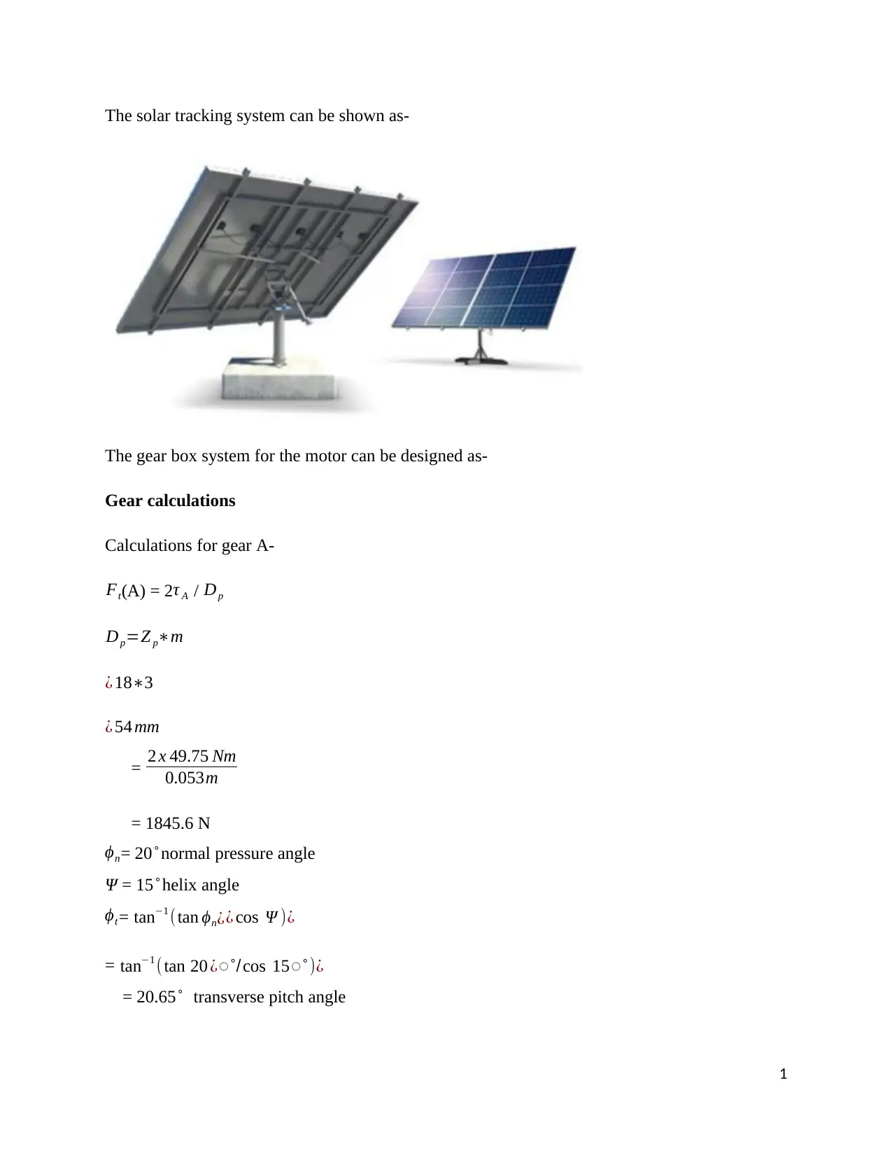
This project outlines the design of a mechanical power transmission system for a solar tracking system, aiming to move solar panels at a controlled speed using an electric motor. The design incorporates gear calculations, speed and torque analysis, and bending stress considerations to ensure efficient and reliable operation. The gear system is designed to reduce the motor's 1460 rpm to a suitable output speed for tracking, with calculations provided for gear dimensions, forces, and stress. The project emphasizes minimizing the weight of the transmission system for mounting on the solar panels. References to relevant research papers are included to support the design process. Desklib offers access to similar projects and solved assignments for students.
tabler-icon-diamond-filled.svg

Contribute Materials

Your contribution can guide someone’s learning journey. Share your documents today.
Document Page
The solar tracking system can be shown as-
The gear box system for the motor can be designed as-
Gear calculations
Calculations for gear A-
Ft(A) = 2τ A / Dp
Dp=Z pm
¿ 183
¿ 54 mm
= 2 x 49.75 Nm
0.053m
= 1845.6 N
ϕn= 20 ̊ normal pressure angle
Ψ = 15 ̊ helix angle
ϕt = tan1 (tan ϕn¿¿ cos Ψ )¿
= tan1 ( tan 20 ¿̊  /cos 15̊  )¿
= 20.65 ̊ transverse pitch angle
1
tabler-icon-diamond-filled.svg

Secure Best Marks with AI Grader

Need help grading? Try our AI Grader for instant feedback on your assignments.
Document Page
Fr(A) = Ft(A) tan ϕt
= 1842 tan 20.65
= 695 N
Fa(A) = Ft(A) tan Ψ
= 1842 tan15
= 494 N
Forces on gear B-
Ft(B) = 2τ B / Dg
Dg=ZBm=453=135 mm
= 2 x 151.43 Nm
0.135 m
= 2244 N
Fr(B) = Ft(B) tan ϕt
= 2244 tan 20.65
= 846 N
Fa(B) = Ft(B) tan Ψ
= 2244 tan15
= 602 N
Forces on gear C-
Ft(C) = 2τC / Dp
2
Document Page
Dp=Z pm=183=54 mm
= 2 x 151.43 Nm
0.054 m
= 5608 N
Fr(C) = Ft(C) tanϕt
= 5608 tan 20.65
= 2114 N
Fa(C) = Ft(C) tan Ψ
= 5608 tan15
= 1503 N
Forces on gear D-
Ft(D) = 2τ D / Dg
Dg=ZDm=523=156 mm
= 2 x 357.99 Nm
0.156 m
= 4589 N
Fr(D) = Ft(D) tan ϕt
= 4589 tan 20.65
= 1730 N
Fa(D) = Ft(D) tan Ψ
= 4589 tan15
= 1230 N
3
Document Page
Calculations regarding the speed and number of teeth on the gears
Uh = U
Ul
U = 1460
156.16
U = 9.34
Where:
Ul =¿ Reduction ratio for second or low speed stage
This is also given as:
Ul =0.88 U
So high speed stage reduction ratio becomes
Uh = U
0.88 U
¿ 12.98
0.88 12.98
¿ 4.094
Given the gear ratio the number of teeth for gear 1 and 2 can be determined. The pinion, gear 1,
should have its number of teeth minimized to reduce the overall size of the gearbox. The number
of teeth is assumed to be 18 as it is the minimum number required to avoid undercutting for spur
gears. If helical gears are selected then with further calculations the minimum number of teeth
may be reduced.
Z1 =¿ Number of teeth in gear 1
¿ 18
Z2 =¿ Number of teeth in gear 2
¿ Z1 Uh ¿ 18 × 4.094 ¿ 73.69 ¿ 74
4
tabler-icon-diamond-filled.svg

Secure Best Marks with AI Grader

Need help grading? Try our AI Grader for instant feedback on your assignments.
Document Page
Altered high speed reduction ratio
Uh =74
18 ¿ 4.11
High Speed Uh = U
Ul
= 9.34
2.362 = 3.95
Low Speed Ul = 0.88 U = 0.88 9.34 = 2.68
Input Shaft Speed-
np = nA = 1460 rpm
Intermediate Shaft Speed-
nBC = nA
U AB
= nA
Uh
= 1460
3.95 = 369.62 rpm
Output Shaft Speed-
nD = nBC
UCD
= nBC
Ul
= 369.62
2.68 = 137.91 rpm
Input Shaft Speed-
ω A = 1460 π
30 = 152.81 rad/s
Intermediate Shaft Speed-
5
Document Page
ωBC = 369.62 π
30 = 38.68 rad/s
Output Shaft Speed-
ωD = 137.91 π
30 = 14.43 rad/s
Input Shaft Torque-
τ A = Pn 1
ω A
=
7500 W
152.81 rad
s
= 49.08 Nm
Intermediate Shaft Torque-
τ BC = Pn 1
ωBC
=
7500 W
49.08 rad
s
= 152.81 Nm
Output Shaft Torque-
τ D = Pn 1
ωD
=
7500 W
14.43 rad
s
= 519.75 Nm
Calculations for the bending stress on the gear
vt = πDnp / (60 x 1000)
= π x 54 x 1460 / 60000
= 4.125 m/s
Kv = 50 / [50 + 137.91vt ]
6
Document Page
= 50/ [50 + 137.91× 4.125 ]
= 0.677
C pf = F
10 d - 0.038 + 0.0005d where F = face width
= 40
10× 52.20 - 0.038 + 0.0005(52.20) d = diametrical pitch
= 0.070
Km = 1 + C pf + Cma
= 1 + 0.070 + 0.164
= 1.32
St = (Ft. Pd / b. J).Ko.Ks.Km.K B.Kv
where Ft = 1845 N
Pd = 0.35
b = 40 mm
J = 0.5
Ko = 1.5
Ks = 1.0
Km = 1.25
K B = 1.0
Kv = 0.65
St = (Ft. Pd / b. J).Ko.Ks.Km.K B.Kv
= ((1843×0.35)/(40×0.5))×1.5×1×1.25×1×0.677
= 40.94 MPa
7
tabler-icon-diamond-filled.svg

Paraphrase This Document

Need a fresh take? Get an instant paraphrase of this document with our AI Paraphraser
Document Page
References
Kalogirou, S. A. (1996). Design and construction of a one-axis sun-tracking system. Solar
Energy, 57(6), 465-469.
Ponniran, A., Hashim, A., & Joret, A. (2011). A design of low power single axis solar tracking
system regardless of motor speed. International Journal of Integrated Engineering, 3(2).
Khan, M. T. A., Tanzil, S. S., Rahman, R., & Alam, S. S. (2010, December). Design and
construction of an automatic solar tracking system. In Electrical and Computer Engineering
(ICECE), 2010 International Conference on (pp. 326-329). IEEE.
Tudorache, T., & Kreindler, L. (2010). Design of a solar tracker system for PV power
plants. Acta Polytechnica Hungarica, 7(1), 23-39.
8
chevron_up_icon
1 out of 8
circle_padding
hide_on_mobile
zoom_out_icon
logo.png

Your All-in-One AI-Powered Toolkit for Academic Success.

Available 24*7 on WhatsApp / Email

[object Object]