Engineering Implementation Project: Solar Pond for Domestic Energy
VerifiedAdded on 2023/04/03
|11
|2730
|110
Project
AI Summary
This engineering implementation project explores the viability of small-scale solar ponds as an alternative energy source to address the global energy crisis. It details the methodology, materials, and process guidelines for constructing a domestic solar pond, including site selection criteria, material analysis, and thermodynamic considerations. The project emphasizes the importance of using readily available materials and minimizing environmental impact. It includes the design of a solar pond, focusing on dimensions, materials, and thermal performance, as well as salt selection and replenishment strategies. The project also addresses algae control and incorporates engineering drawings and analysis to optimize the pond's efficiency and structural integrity, aiming to educate the public about green and renewable energy solutions.
TITLE: ENGINEERING IMPLEMENTATION PROJECT
INTRODUCTION
In the recent years there have been an energy crisis across the globe. The main sources of energy which
were coal, natural gas and petroleum product are being depleted. This has led to a very big gap between
the energy demand and supply across all nations. This scarcity has made production processes to be
very uneconomical. Therefore, engineers have been put to task to find suitable alternatives which may
quest the global need for energy. solar energy has been suggested as the suitable alternative. Solar
radiations are experienced in almost every country in the world. This is advantageous since no raw
materials are required in the extraction of this energy. Unlike hydrocarbon fuels solar energy has lower
carbon footprint hence minimizing instances of pollution. The solar energy can be utilized in
construction of domestic solar ponds. The construction of solar ponds utilizes the energy differences in
the LCZ (lower convective zone) and UCZ (upper convective zone) regions to generate energy. In this
project small scale solar pond will be analyzed. This is because the energy need is not available to the
poor local household. Therefore, small scaled solar pond should be economical and easy to start and
should provide the domestic energy needs.
Although our technology faces stiff competition to the utilization of solar panel it remains relevant since
solar cells are relatively expensive and have lower efficiencies compared to our domestic solar pond
which have efficiencies of over 60%.
METHODOLOGY
Materials
(i)heat exchanger
(ii)Evaporimeter
(iii)centrifugal/gear pumps
(iv)connecting pipes
(v)salts (preferably sodium chloride)
(vi)volatile liquid
(vii)alternator / turbine
(vii)constant water source
(vii)connecting cables
Paraphrase This Document
Need a fresh take? Get an instant paraphrase of this document with our AI Paraphraser
Necessary guidelines on area of construction
(i)The area of construction of the solar pond should not be too close to the water table. This is because
the water at the water table may cause cooling effect on the LCZ hence reducing the amount of
electrical energy that can be generated. Also the water in the water table might dissolve the saline
environment present in the LCZ.
(ii)The solar pond should be constructed in areas close to a water source. This is to minimize the effort
required in flushing the upper mixed part of the pond.
(iii)The solar pond should be close to the domestic home where the electrical energy generated should
be used. This will reduce transmission cost and instances of heat loss by resistance of cables hence
making electrical energy production to be economical.
(iv)The thermal conductivity of the soil should be tested before constructing a solar pond. Places which
have soils with high thermal conductivity should be avoided while those having lower thermal
conductivity should be preferred. This is because high thermal conductivity of the soil encourages
thermal heat loss to the surrounding therefore reducing the overall efficiency of the pond.
(v)In extreme cases the latitude of the solar pond should also be a determining factor, the construction
site should be in areas where there are significant solar radiations, this means that our technology will
not be viable in north and south poles due to its low efficiencies in the areas.
Process Guidelines
(i)There would be creation of user profile and the product life cycle map of a typical solar pond. This will
include an innovation matrix which will help in understanding of the appropriate design process. There
will be analysis of the materials used in the making of the pond, their availability, the context area of the
pond, the service and which systems will be implemented to achieve our objectives.
(ii)Analysis of the properties of materials under investigation will be conducted. This will include
performing radiations tests of the materials. Calculations of their thermal conductivity should be done
therefore getting the necessary parameters which should be used to determine the appropriate depth,
breadth and width of the solar pond system.
(ii)The next process will be investigation of optical properties of the fluid used in the pond. The fluid
used should be able to allow solar radiations to penetrate beneath while having good conductivity. Since
most liquids have significantly poor levels of thermal conductivity, this will pose a problem in the overall
efficiency of the system. This means that other measure has to be put in place such as the reduction of
deflected beams of radiations should be minimal as possible so as to improve the efficiency of the solar
pond.

(iii)Development of ethics/ sustainability matrix, this will be combined with the engineering data
available from the earlier versions of solar ponds. This analysis will be relevant since it will analyze each
set of design while showcasing their weakness and how each of the limitation of the previous design
should be improved to meet our current needs. This will include looking at materials which have
appropriate properties for construction of solar ponds hence falling in the scope of the intended goal.
(iv)There will be comparison of large and smaller scale solar ponds and how each is efficient. This will
include the calculations of the initial investments of each, and if the risks of construction of each is
worth it. This will be done by the assignment of points for the best performing pond and their
economical scale in solving the energy crisis in the world.
(v)The first story board of the design intention will be created, this will therefore, include innovation,
designing for change and all design essentials. This means that our design should be adaptable to
different conditions for it to be viable. The conditions might be different weather patterns experienced,
this means that our design should not fail due to winds or heavy rainfall that may be experienced in the
construction sites. Therefore, our engineering design should tackle the monsoon winds experienced in
Australia which might create a massive heat loss in the upper sections of our solar ponds.
(vi)Geometric model of a typical solar pond should be generated. The pond will be rectangular shaped at
the top which will simplify the calculation on the thickness of upper convective zone(UCZ), lower
convective zone(LCZ) and the non-convective zone(NCZ). The pond should be modelled with materials
resistant to corrosion this is because the high amount of salt concentration in the pond water will cause
accelerated corrosion in all metallic parts used in construction of the system.
(vii)calculations of the pumping systems used should be done. Centrifugal or gear pumps should be used
in ensuring constant volumetric flow of water in and out of the solar pond. Since in this case high
pressure is needed gear pumps will be appropriate as compared to centrifugal pumps. Therefore,
different connections of the pumping system should be considered. The pumps might be connected in
parallel to minimize the workload on only one pump, causing increased life span of the pumps. Or they
might be connected in series where centrifugal pumps are used so as increase the effective pressure.
(viii)morphological analysis should be done on the piping system of the solar pond, the pipes should be
of standard diameter and should be insulated with a suitable material to minimize instances of excess
heat loss to the surrounding. The pipes should also be highly polished so that they can act as poor
emitters of thermal heat at night.
(ix)Create parametric drawing plan views, this will help in designing against failure, therefore the
constructor of the solar pond will have a better understanding of the equilibrium conditions for the
design. This views will be modelled by use of appropriate engineering modelling tools such as AutoCAD.
This will enable easy performance of stress tests, calculations of bending moments of the ponds and the
stress intensity factor which might be used to eliminate the instances of cracking of the pond.
(x)Perform thermodynamic analysis of the pond, this will include calculations of the efficiency of
different layers of the pond, finding the conductivity factor of water and finding the amount of heat
energy stored in the solar pond.
(xi)Designing the heat exchanger, the heat exchanger will be used to heat volatile liquid such as
propane. Therefore, the design of the heat exchanger should be very efficient to ensure maximum heat
⊘ This is a preview!⊘
Do you want full access?
Subscribe today to unlock all pages.
Trusted by 1+ million students worldwide
transfer between the liquid collected from LCZ and propane. Therefore, efficient length of heat
exchanger should be used to achieve this situation.
(xi)Designing of the turbine used to generate electricity. This will constitute of an alternator connected
with appropriate gearing system to achieve higher velocity ratio so that a sustainable generation of
electricity could be achieved. The shafts of the alternator will be driven by the high pressure generated
in heating volatile liquid in the evaporimeter.
(xii)Creation of engineering poster to elaborate the design, that will educate the public about green and
renewable energy which can be used to eliminate hydrocarbon energy that have high carbon footprint
hence causing destruction of the environment by global warming.
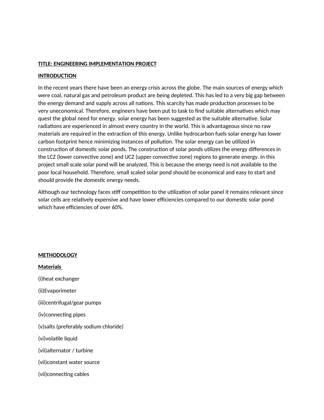
DESIGN OF SOLAR POND
A solar pond of dimension 1.6meters by 1.6meters is constructed in the tropical area that receives
significant solar radiations. The solar pond is maintained at the depth of 2.5meters, these parameters
makes the pond to have good structural integrity as a domestic pond while achieving the goals of
production of electricity. Constant levels of water in the pond is maintained by the use of pumps
powered by the electricity generated by the solar ponds. The walls of the ponds are inclined at θ=12
degrees this ensures maximum absorption of solar radiations.
Fig1.0 plan design of solar pond
exchanger should be used to achieve this situation.
(xi)Designing of the turbine used to generate electricity. This will constitute of an alternator connected
with appropriate gearing system to achieve higher velocity ratio so that a sustainable generation of
electricity could be achieved. The shafts of the alternator will be driven by the high pressure generated
in heating volatile liquid in the evaporimeter.
(xii)Creation of engineering poster to elaborate the design, that will educate the public about green and
renewable energy which can be used to eliminate hydrocarbon energy that have high carbon footprint
hence causing destruction of the environment by global warming.
DESIGN OF SOLAR POND
A solar pond of dimension 1.6meters by 1.6meters is constructed in the tropical area that receives
significant solar radiations. The solar pond is maintained at the depth of 2.5meters, these parameters
makes the pond to have good structural integrity as a domestic pond while achieving the goals of
production of electricity. Constant levels of water in the pond is maintained by the use of pumps
powered by the electricity generated by the solar ponds. The walls of the ponds are inclined at θ=12
degrees this ensures maximum absorption of solar radiations.
Fig1.0 plan design of solar pond
Paraphrase This Document
Need a fresh take? Get an instant paraphrase of this document with our AI Paraphraser
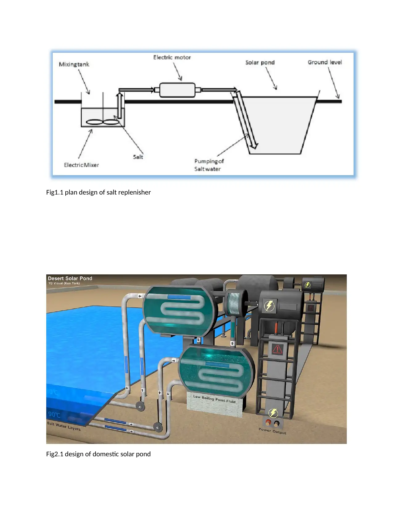
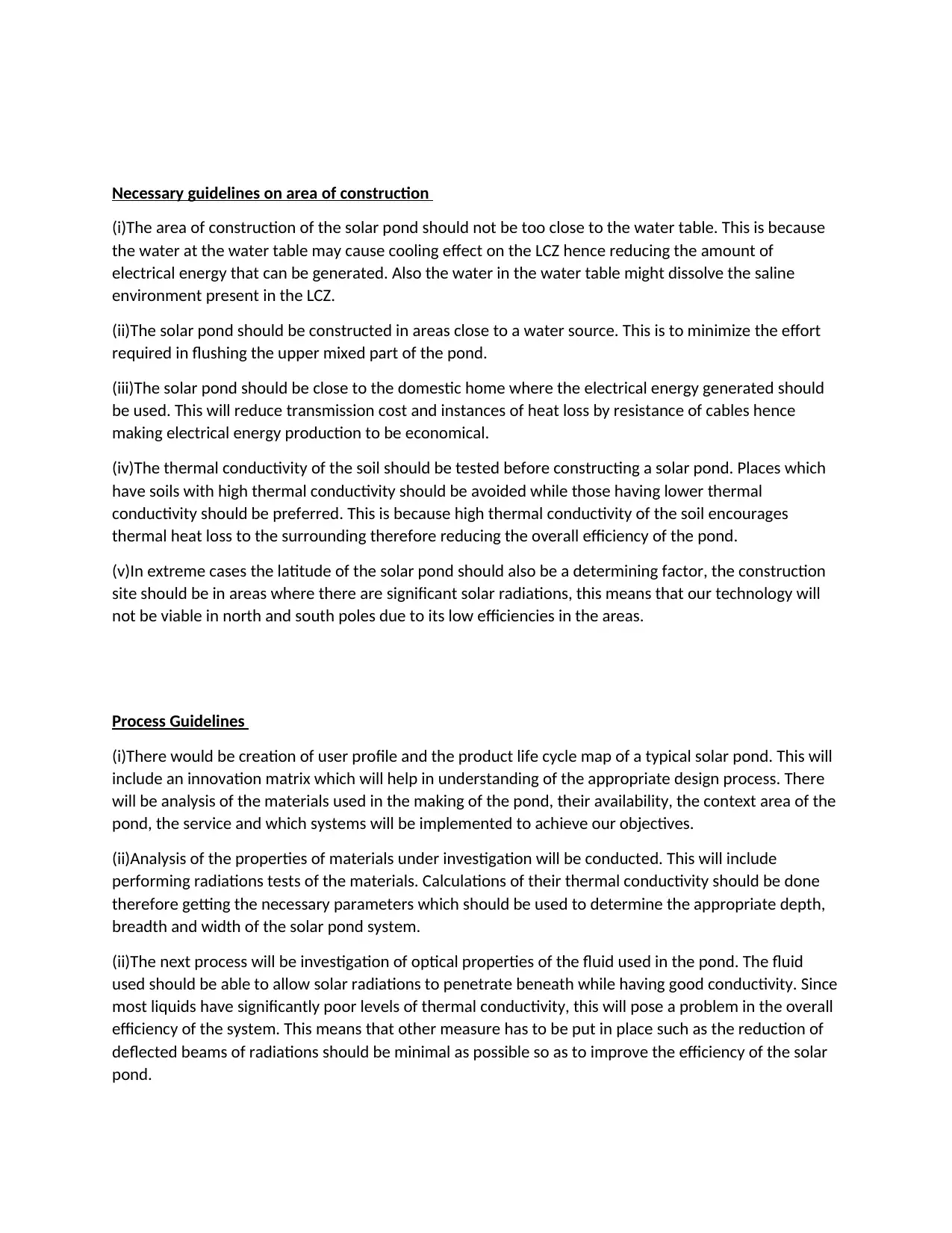
Fig1.1 plan design of salt replenisher
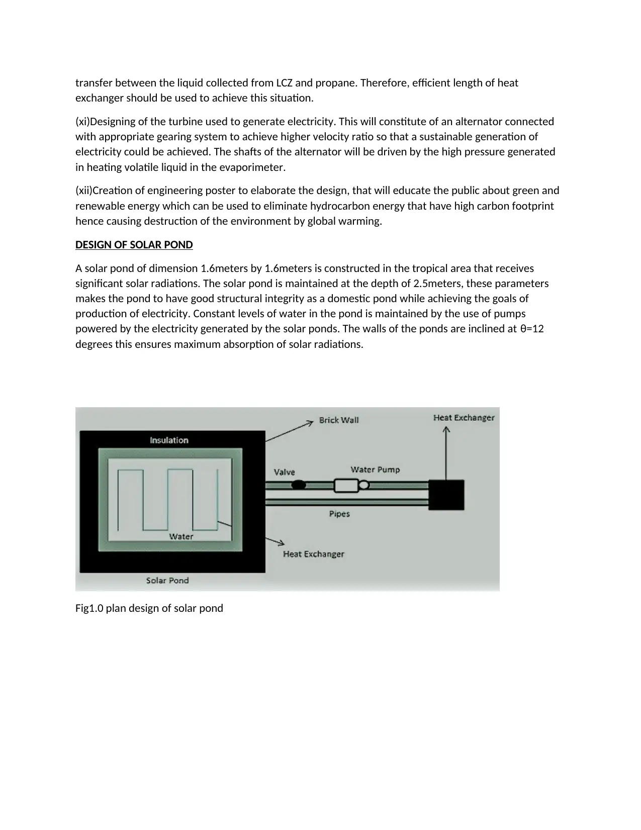
Fig2.1 design of domestic solar pond
Fig2.1 design of domestic solar pond
The standard method of single brick construction is used and cemented plaster is applied at the surface
of the bricks. At the inner sections of the pond 50cm thick layer of sand is applied which acts as thermal
insulator which minimizes heat loss to the sides of the pond. Also a polypropylene sheet is used to
uniformly cover the internal surface of the pond this prevents seepage of saline water to the cemented
regions of the pond.
To perform relevant engineering analysis Temperature sensor are placed at the UCZ, NCZ, LCZ regions to
monitor the performance of the pond. Also hydrometer is placed in the pond to measure the relative
densities of the saline layer and indicate if salt replenishment is needed.
Thermal performance
By assuming steady state condition thermal performance of a pond can be calculated by the following
formulae
Qu=Qa−Qc
Where Qu-useful heat extracted
Qc-heat losses
Qa-solar energy absorbed
The efficiency of the solar pond can be further explained by the equation
η=η0− Qu
I
Salt selection
The salt used in the construction of the solar pump should possess various factor discussed below
(i)Its solubility in water should not be greatly affected by the temperature changes in the environment
⊘ This is a preview!⊘
Do you want full access?
Subscribe today to unlock all pages.
Trusted by 1+ million students worldwide
(ii)it should be relatively cheap to minimize the cost of maintenance of the pond
(iii)it should be environmental friendly and not act as pollutant to the animal and plant life present in
the pond.
Most of the salts do not satisfy this conditions completely, the only salt that is relevant for the above
factors is sodium chloride, therefore it is always given a priority when it comes to construction of
domestic solar ponds.
Salt replenishment
Salt layers of the solar ponds should always be replenished seasonally; this is because the concentration
of the salts at the LCZ regions will diffuse to the neighboring layer causing formation of internal
convective zones due to small differences in saline concentration. This replenishment of salts is done by
regularly pumping brine to the LCZ regions. The upper layer of the solar pond should also be flushed
with fresh water so as to maintain concentration gradient between the two layers. This diffusion of salts
across the concentration gradient can be calculated by the following formulae.
QM = ( S−s2 ) D
B
Where B= thickness of the gradient zone
D=mass diffusion coefficient
S, S2= salinity of the UCZ and LCZ respectively
Algae control
The saline environment in the pond may encourage growth of algae and other aquatic plants. This plants
may cover the upper surface of the pond that receives the solar radiations. This protective cover may
make the UCZ region of the pond to be blocked for maximum exposure of solar radiations. Therefore,
our domestic solar pond is supposed to be serviced every time so that generation of electricity can be
achieved. In long run this process might be tedious and expensive. Therefore, a suitable method of algae
control is supposed to be devised. The algae growth can be controlled by application of salts such a
copper (II) sulphate or bleaching powder which hinders the growth of algae and eutrophication of
aquatic plants. The way the copper(II)sulphate behaves in the pond will be affected by the PH of the
water. In case of alkaline environment, the copper sulphate will not dissolve but will settle at the LCZ
region of the pond. But in case of lower pH the salt will dissolve giving the pond a uniform blue color.
Dust may also be a hindrance to maximum solar radiations this might be solved by the use of sweep nets
to collect dust and leaves floating in the top of the solar pond.
Paraphrase This Document
Need a fresh take? Get an instant paraphrase of this document with our AI Paraphraser
Pond stability
A solar pond is said to be statistically stable if its density increases with the increase in depth of the
pond. This means therefore that LCZ region is supposed to have a higher density than that of UCZ. But in
some cases this may not be entirely be the same. The UCZ region may be affected by rains or winds this
may cause convectional cooling in the LCZ region. For the pond to be stable engineers should use
perturbation analysis of basic laws of conservation of mass and energy to come with various parameters
that will help them minimize the instances of these incidences.
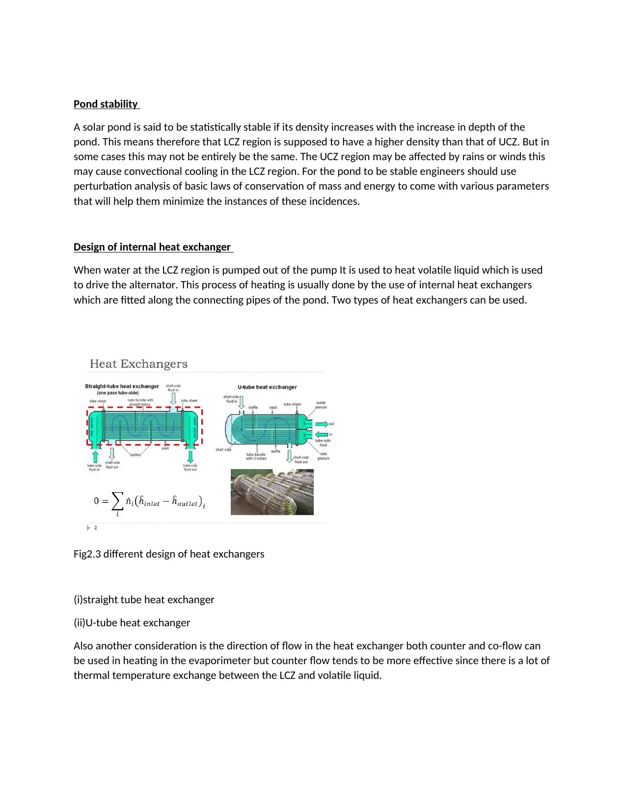
Design of internal heat exchanger
When water at the LCZ region is pumped out of the pump It is used to heat volatile liquid which is used
to drive the alternator. This process of heating is usually done by the use of internal heat exchangers
which are fitted along the connecting pipes of the pond. Two types of heat exchangers can be used.
Fig2.3 different design of heat exchangers
(i)straight tube heat exchanger
(ii)U-tube heat exchanger
Also another consideration is the direction of flow in the heat exchanger both counter and co-flow can
be used in heating in the evaporimeter but counter flow tends to be more effective since there is a lot of
thermal temperature exchange between the LCZ and volatile liquid.
A solar pond is said to be statistically stable if its density increases with the increase in depth of the
pond. This means therefore that LCZ region is supposed to have a higher density than that of UCZ. But in
some cases this may not be entirely be the same. The UCZ region may be affected by rains or winds this
may cause convectional cooling in the LCZ region. For the pond to be stable engineers should use
perturbation analysis of basic laws of conservation of mass and energy to come with various parameters
that will help them minimize the instances of these incidences.
Design of internal heat exchanger
When water at the LCZ region is pumped out of the pump It is used to heat volatile liquid which is used
to drive the alternator. This process of heating is usually done by the use of internal heat exchangers
which are fitted along the connecting pipes of the pond. Two types of heat exchangers can be used.
Fig2.3 different design of heat exchangers
(i)straight tube heat exchanger
(ii)U-tube heat exchanger
Also another consideration is the direction of flow in the heat exchanger both counter and co-flow can
be used in heating in the evaporimeter but counter flow tends to be more effective since there is a lot of
thermal temperature exchange between the LCZ and volatile liquid.
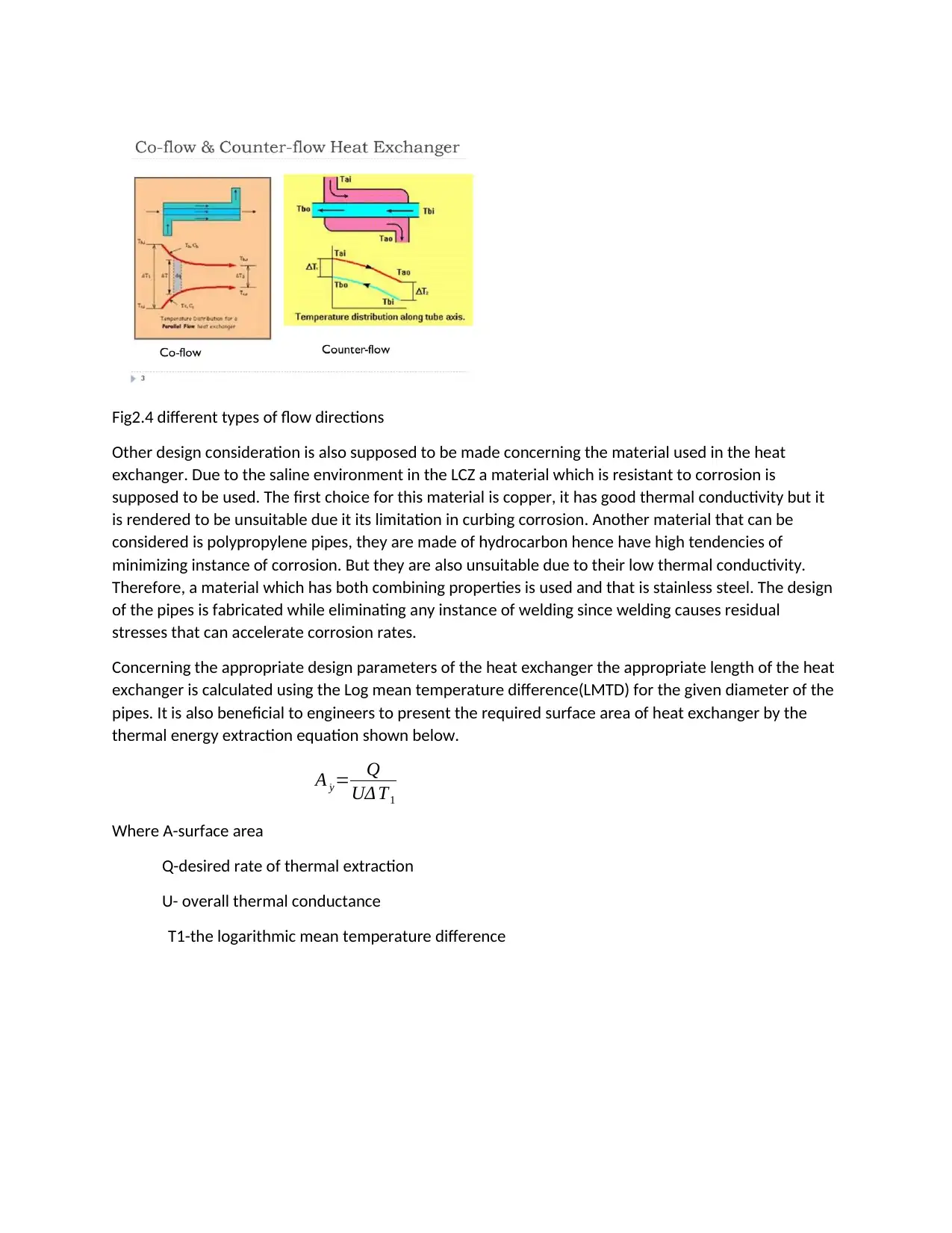
Fig2.4 different types of flow directions
Other design consideration is also supposed to be made concerning the material used in the heat
exchanger. Due to the saline environment in the LCZ a material which is resistant to corrosion is
supposed to be used. The first choice for this material is copper, it has good thermal conductivity but it
is rendered to be unsuitable due it its limitation in curbing corrosion. Another material that can be
considered is polypropylene pipes, they are made of hydrocarbon hence have high tendencies of
minimizing instance of corrosion. But they are also unsuitable due to their low thermal conductivity.
Therefore, a material which has both combining properties is used and that is stainless steel. The design
of the pipes is fabricated while eliminating any instance of welding since welding causes residual
stresses that can accelerate corrosion rates.
Concerning the appropriate design parameters of the heat exchanger the appropriate length of the heat
exchanger is calculated using the Log mean temperature difference(LMTD) for the given diameter of the
pipes. It is also beneficial to engineers to present the required surface area of heat exchanger by the
thermal energy extraction equation shown below.
A ˙y= Q
UΔ T1
Where A-surface area
Q-desired rate of thermal extraction
U- overall thermal conductance
T1-the logarithmic mean temperature difference
⊘ This is a preview!⊘
Do you want full access?
Subscribe today to unlock all pages.
Trusted by 1+ million students worldwide

BIBLIOGRAPHY
[1]www.pec.org.pk/sCourse.../RENEWABLE%20INTRODUCTION.ppt ; accessed on 17 Nov, 2013.
[2]Akbarzadeh, A., Tundee, S., & Singh, R. “Heat Extraction from salinity gradient solar ponds using heat
pipe heat exchangers”, Solar Energy, pp 1706-1716 (2010).
[3]Frohlich, C., and R. W. Brusa (1981), "Solar Radiation and its Variation in Time", Solar Physics 74, 209.
Tabor H and Weinberger Z (1980) Non convecting solar ponds.
[4]Solar Energy Handbook, Chapter 10 (edited by Kreider), New York: McGraw-Hill.
[5]http://www.kentchemistry.com/links/Kinetics/SolubilityCurves.htm ; accessed on 17 Nov, 2013.
[6]Incropera, F.P., DeWitt, D.P., Fundamentals of Heat and Mass Transfer, Ch 11, Fourth Edition,. ISBN:
0-471-30460-3.
[7] kevin.k.ngatia 2019. Png www.youtube.vid
[8] heat exchanger.png www.google.com
Paraphrase This Document
Need a fresh take? Get an instant paraphrase of this document with our AI Paraphraser

1 out of 11

Your All-in-One AI-Powered Toolkit for Academic Success.
+13062052269
info@desklib.com
Available 24*7 on WhatsApp / Email
![[object Object]](/_next/static/media/star-bottom.7253800d.svg)
Unlock your academic potential
Copyright © 2020–2026 A2Z Services. All Rights Reserved. Developed and managed by ZUCOL.