Project: Design and Fabrication of a Solar Power Converter System

Verified

Added on  2021/05/31

|8
|1786
|346
Project
AI Summary
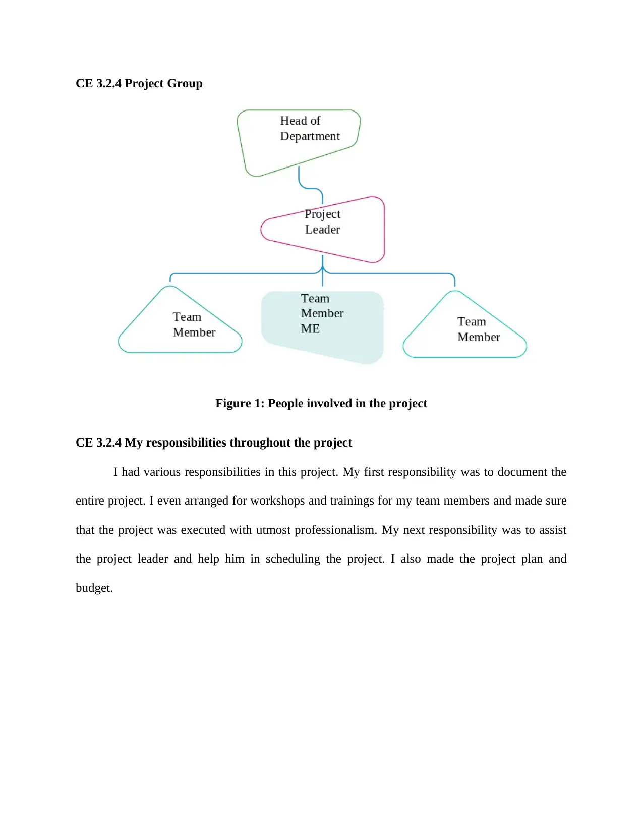
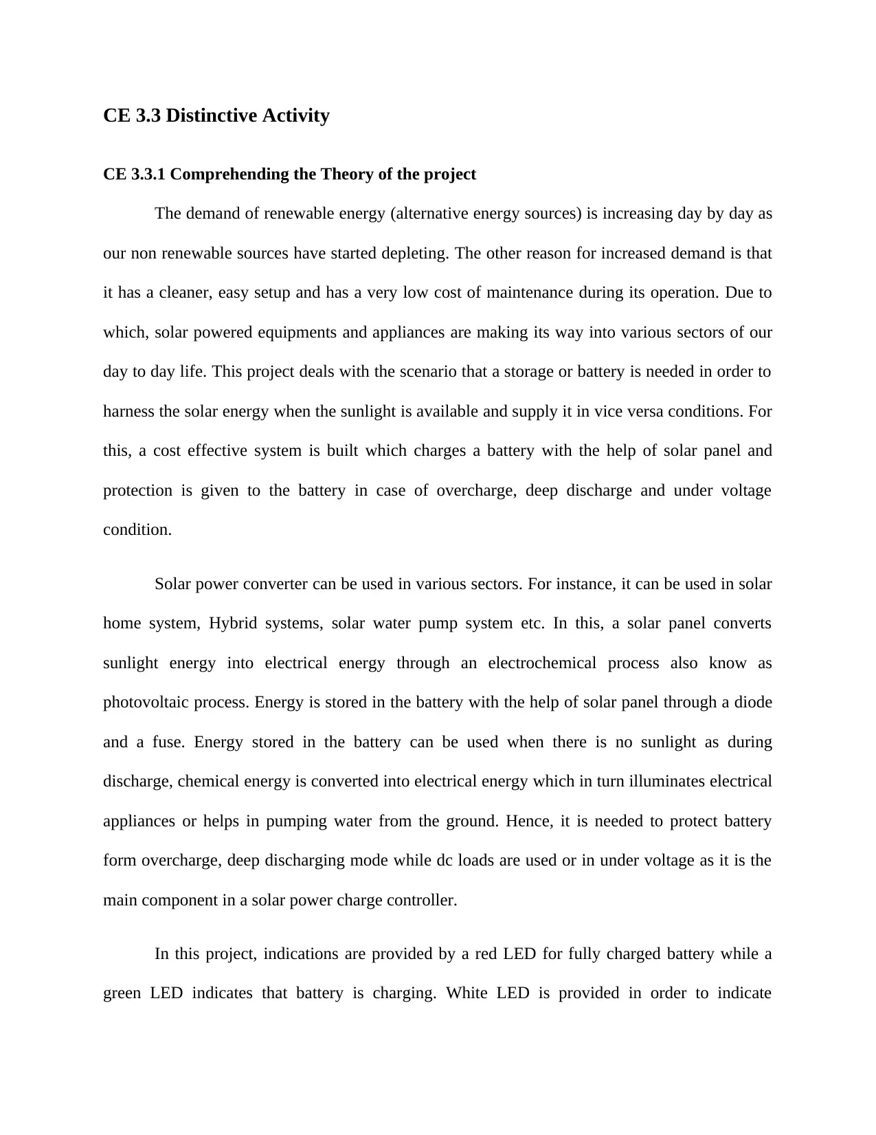
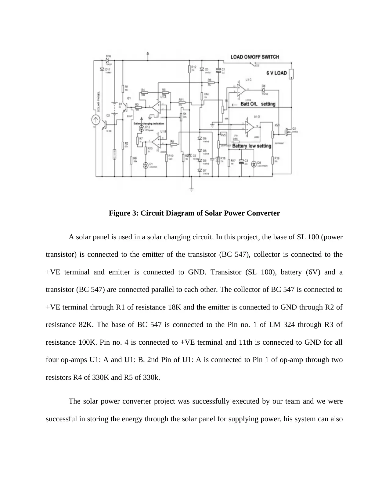
This document presents a student's project report on the design and fabrication of a solar power converter. The project addresses the increasing demand for renewable energy sources by designing a system to convert and control solar power. The report details the project's objectives, which include designing and fabricating a solar power converter and controlling the converted power. It describes the project's background, including the benefits of solar power and the components used, such as photovoltaic cells, batteries, LM324, and transistors. The student's responsibilities included project documentation, team training, scheduling, project planning, and budget management. The report outlines the project's theory, including the conversion of sunlight into electrical energy and the use of a charge controller to protect the battery. It also discusses the engineering knowledge and skills applied, the issues encountered (design problems), and the solutions implemented. The student's contribution included project design and leading the team. The report concludes with a project review, highlighting the successful completion of the project and potential future work, such as optimizing the system for UPS applications.
tabler-icon-diamond-filled.svg

Contribute Materials

Your contribution can guide someone’s learning journey. Share your documents today.
Document Page
CE 3.1 Project Information
Name of the project: Design and Fabrication of Solar Power Converter
Location of the project: Please fill
Project Duration: Please fill
Organization: Please fill
Role and Designation during the time: Team Member of the project
CE 3.2 Project Background
CE 3.2.1 Characteristics of the project
The project of Design and Fabrication of Solar Power Converter was my third important
project in engineering career. The demand of renewable energy (alternative energy sources) is
increasing day by day as our non renewable sources have started depleting. The other reason for
increased demand is that it has a cleaner, easy setup and has a very low cost of maintenance
during its operation. Due to which, solar powered equipments and appliances are making its way
into various sectors of our day to day life. The main benefit of this project is that the solar power
could be easily converted as well as controlled easily.
CE 3.2.2 Objectives developed for the project
The project of Design and Fabrication of Solar Power Converter had several objectives.
The most important objectives for this particular project are as follows:
To design and fabricate a Solar Power Converter.
To control the converted solar power properly.
tabler-icon-diamond-filled.svg

Secure Best Marks with AI Grader

Need help grading? Try our AI Grader for instant feedback on your assignments.
Document Page
CE 3.2.4 Project Group
Figure 1: People involved in the project
CE 3.2.4 My responsibilities throughout the project
I had various responsibilities in this project. My first responsibility was to document the
entire project. I even arranged for workshops and trainings for my team members and made sure
that the project was executed with utmost professionalism. My next responsibility was to assist
the project leader and help him in scheduling the project. I also made the project plan and
budget.
Document Page
CE 3.3 Distinctive Activity
CE 3.3.1 Comprehending the Theory of the project
The demand of renewable energy (alternative energy sources) is increasing day by day as
our non renewable sources have started depleting. The other reason for increased demand is that
it has a cleaner, easy setup and has a very low cost of maintenance during its operation. Due to
which, solar powered equipments and appliances are making its way into various sectors of our
day to day life. This project deals with the scenario that a storage or battery is needed in order to
harness the solar energy when the sunlight is available and supply it in vice versa conditions. For
this, a cost effective system is built which charges a battery with the help of solar panel and
protection is given to the battery in case of overcharge, deep discharge and under voltage
condition.
Solar power converter can be used in various sectors. For instance, it can be used in solar
home system, Hybrid systems, solar water pump system etc. In this, a solar panel converts
sunlight energy into electrical energy through an electrochemical process also know as
photovoltaic process. Energy is stored in the battery with the help of solar panel through a diode
and a fuse. Energy stored in the battery can be used when there is no sunlight as during
discharge, chemical energy is converted into electrical energy which in turn illuminates electrical
appliances or helps in pumping water from the ground. Hence, it is needed to protect battery
form overcharge, deep discharging mode while dc loads are used or in under voltage as it is the
main component in a solar power charge controller.
In this project, indications are provided by a red LED for fully charged battery while a
green LED indicates that battery is charging. White LED is provided in order to indicate
Document Page
overcharge, deep discharge or under voltage condition. Charge controller also uses MOSFET as
power semiconductor switch to ensure cut off the load in low battery or overload condition.
When the battery gets fully charged, a transistor is used in order to bypass the solar energy to a
dummy load which protects the battery from getting over charged. A solar charge controller or
regulator is a small box placed between a solar panel and a battery consisting of solid state
circuits PCB. They are used to regulate the amount of charge coming from the solar panel in
order to protect the battery from getting overcharged. Adding to this, it can also be used to allow
different dc loads and supply appropriate voltage.
Figure 2: Block Diagram of Solar Power Converter
The most significant components of this project were Photovoltaic Cells and Solar panel,
battery, LM 324 and Transistors.
i) Photovoltaic Cells and Solar panel: Photovoltaic (PV) cells are the one which are made
from special materials called semiconductors like Silicon. They are used for conversion of light
into electricity using semiconductor materials that exhibit the photovoltaic effect. When the light
strikes the cell; certain amount of light gets absorbed into the semiconductor material, which
tabler-icon-diamond-filled.svg

Secure Best Marks with AI Grader

Need help grading? Try our AI Grader for instant feedback on your assignments.
Document Page
eventually triggers the flow of electrons that causes current to flow. Solar panel is a panel
designed to absorb sun’s rays in order to generate electricity or heat. A PV module is a packaged
consisting of solar cells. Solar panels constitute the solar array of a PV system that helps in
generating and supplying electricity to commercial and residential sectors.
ii) Battery: In this project a Sealed Rechargeable Battery (6V4.5AH/20HR) is used in
order to store energy. An Electrical battery converts chemical energy directly into electrical
energy comprising of one or more electro chemical cells.
iii) LM 324: It is a general purpose op-amp consisting of four independent, high-gain,
internally compensated operational amplifiers designed to operate from a single power supply
over wide range of voltages. It has a wide range of applications such as in transducer amplifiers,
DC gain Blocks and Conventional op-amp circuits. Opamps in LM 324 are used as comparators
in this project.
iv) Transistors: There are three types of transistors used in this project. These are SL 100,
BC 547, IRF 630.
The schematic diagram of this project is given below:
Document Page
Figure 3: Circuit Diagram of Solar Power Converter
A solar panel is used in a solar charging circuit. In this project, the base of SL 100 (power
transistor) is connected to the emitter of the transistor (BC 547), collector is connected to the
+VE terminal and emitter is connected to GND. Transistor (SL 100), battery (6V) and a
transistor (BC 547) are connected parallel to each other. The collector of BC 547 is connected to
+VE terminal through R1 of resistance 18K and the emitter is connected to GND through R2 of
resistance 82K. The base of BC 547 is connected to the Pin no. 1 of LM 324 through R3 of
resistance 100K. Pin no. 4 is connected to +VE terminal and 11th is connected to GND for all
four op-amps U1: A and U1: B. 2nd Pin of U1: A is connected to Pin 1 of op-amp through two
resistors R4 of 330K and R5 of 330k.
The solar power converter project was successfully executed by our team and we were
successful in storing the energy through the solar panel for supplying power. his system can also
Document Page
be upgraded to control normal UPS, when connected with the solar charger will convert to
SOLAR INVERTER/UPS with solar charge as priority.
CE 3.3.2 Engineering Knowledge and Skills applied in the project
This particular project required intense knowledge of electrical power engineering for the
perfect completion. I had used my knowledge of electrical engineering for the perfect project
completion. I did not have clear idea regarding this project; however, after proper training all of
my doubts were absolutely clarified. My team members and team leader were responsible for the
completion of the project. My knowledge of electrical engineering has helped me to execute my
responsibilities in the project perfectly.
CE 3.3.4 Identified issues and their solutions
CE 3.3.4.1 Issues
The most significant problem that I faced in this project of Design and Fabrication of
Solar Power Converter was in the designing part. The team member, who was supposed to make
the design, could not do it properly and thus, the output was coming erroneous. My team
members were unable to find the problem within the project.
CE 3.3.4.2 Solution
I utilized my intellect and professional skills and was able to find out the issue that was
present in the design. I therefore, myself, made the entire design of the project and thus was
successful in completing the entire project perfectly.
tabler-icon-diamond-filled.svg

Paraphrase This Document

Need a fresh take? Get an instant paraphrase of this document with our AI Paraphraser
Document Page
CE 3.3.5 Plan to produce creative and innovative work
Our plan was to complete the project of Design and Fabrication of Solar Power Converter
perfectly. The plan was to produce creative and innovate work by working together with my
fellow team members and team leader and segregating the work.
CE 3.4 Project review
CE 3.4.1 Project overview
This project of Design and Fabrication of Solar Power Converter was completed
properly. We transmitted the primary as well as the secondary data that was taken from any
patient from the side of doctor by utilizing modules of GSM. The probable future work mainly
includes the optimization of ARM9, ARM 11 and hardware system. This particular system has
several benefits like the lower operation costs, easy to utilize, wide area range, large capability,
effective as well as strong expandability. The up gradation of this particular setup is extremely
easy that makes this system open for the future.
CE 3.4.2 My Contribution to the work
I was an important part of the work. My major contribution to this project was the
documentation part. I even made the list of raw materials required in this project and arranged all
of them. I also assisted my project leader during the project tenure and in absence of him, I
leaded the team with my leadership skills. I also organized workshops and trainings for my team
members and made the design of the project.
chevron_up_icon
1 out of 8
circle_padding
hide_on_mobile
zoom_out_icon
logo.png

Your All-in-One AI-Powered Toolkit for Academic Success.

Available 24*7 on WhatsApp / Email

[object Object]