Split Phase Motor Control: Diagram, Methods and Applications

Verified

Added on  2023/06/11

|10
|819
|469
Report
AI Summary
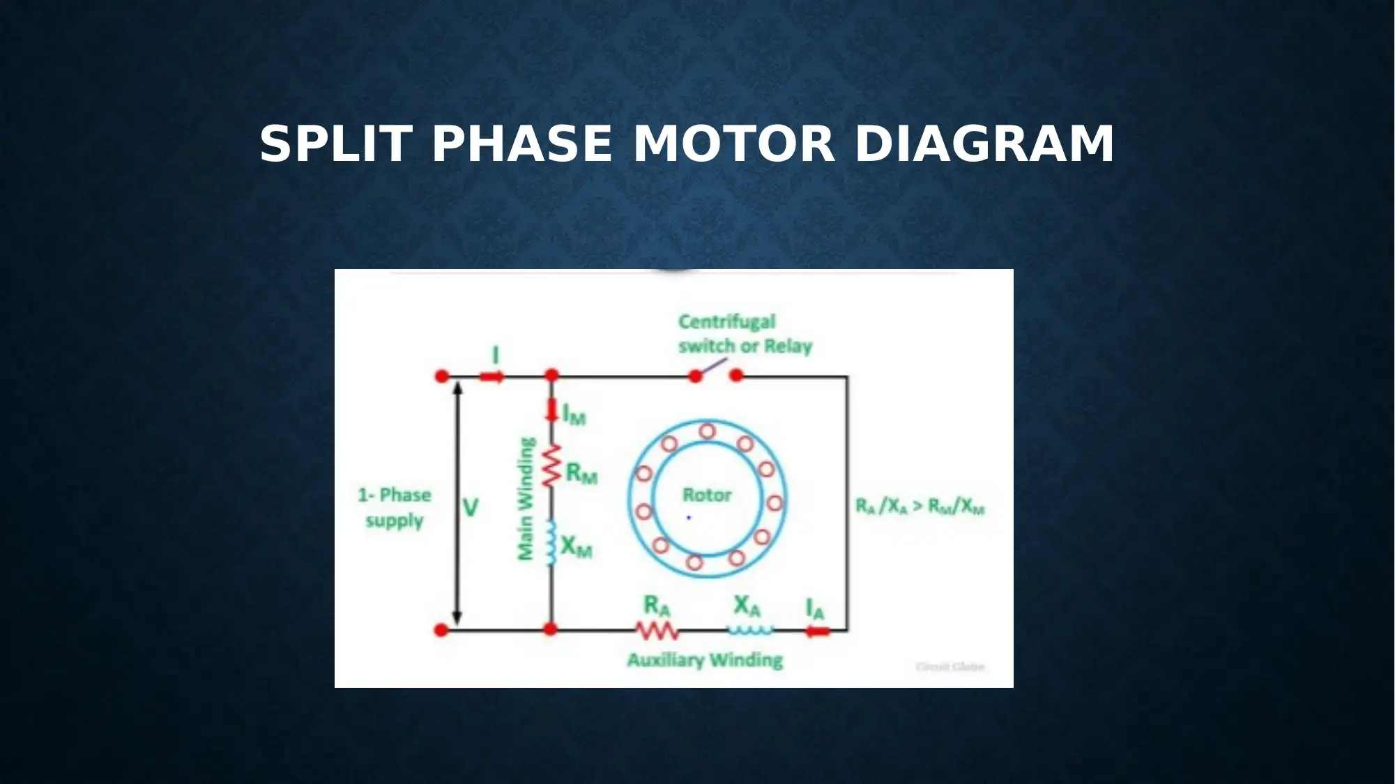
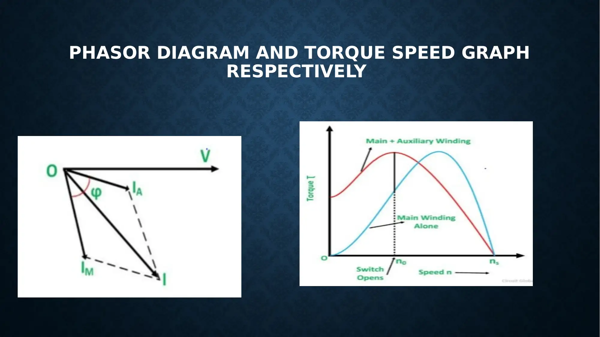
This report provides an overview of split phase motor control, detailing the motor's construction with a single cage blade and stator containing main and initial windings. It explains the operational principles, including the role of centrifugal switches and transfer relays in controlling the windings. The report further discusses various control methods, such as altering the number of poles, cascading the motors, modifying the frequency and source power, and adding blade resistance. Phasor diagrams and torque-speed graphs are included to illustrate the motor's behavior under different control conditions. This document is available on Desklib, a platform offering a range of study tools and solved assignments for students.
Document Page
SPLIT PHASE AND CONTROL
Name of Student
Institution Affiliation
tabler-icon-diamond-filled.svg

Paraphrase This Document

Need a fresh take? Get an instant paraphrase of this document with our AI Paraphraser
Document Page
INTRODUCTION:
The split phase remains likewise recognised equally a confrontation twitch
motorised. It takes a sole birdcage blade, besides its stator takes dual windings
recognised equally key winding beside initial winding (Lobsiger, 2015).
Equally the windings remain expatriate 90 degrees trendy planetary. The core
winding takes actual little resistance besides a great revealing reactance though
the initial winding takes great resistance besides little inductive reactant (Senty,
2012).
Document Page
SPLIT PHASE MOTOR DIAGRAM
Document Page
The current trendy the dual windings remains not equivalent equally a consequence the
revolving arena remains not constant (Works, 2001).
Henceforth, the initial rotation remains lesser, of the directive of 1.5 towards 2 intervals of the
ongoing consecutively rotation (Herman, 2016).
On the initiative of the motorised equally, the windings remain linked to trendy equivalent.
(Rexford, 2004).
tabler-icon-diamond-filled.svg

Paraphrase This Document

Need a fresh take? Get an instant paraphrase of this document with our AI Paraphraser
Document Page
Uncertainty the engines remain valued around 100 watts otherwise extra; a centrifugal control
remains castoff towards remove the initial winding beside for the lesser loop engines transmit
remains castoff for separating of the winding (Bhattacharya, 2015).
A transmit remains linked trendy sequence by the key winding.
Document Page
On the initial, the weighty current movement trendy the tour, besides the
interaction of the transmit grow locked (Johns, 2011).
Consequently, the initial winding remains trendy the circuit, then takes the
motorised achieve the determined rapidity, the current trendy the transmit
twitch declining.(Herman, 2009).
The current trendy the supplementary winding ( lA) remains around trendy
stage through the streak power (Bhattachaya, 2006)(Keijik, 2008).
Document Page
PHASOR DIAGRAM AND TORQUE SPEED GRAPH
RESPECTIVELY
tabler-icon-diamond-filled.svg

Paraphrase This Document

Need a fresh take? Get an instant paraphrase of this document with our AI Paraphraser
Document Page
CONTROL OF THIS MOTOR
And it can be controlled through the following:
i. Through altering the number of rods: rapidity remains circuitously comparative towards the number of
rods for a continuous occurrence (Campbell, 1987).
ii. Pouring the engines: the rapidity of the blades remains equivalent towards 120*f/(P1#P2.) extra through
altering the rods the rapidity can diverse. Likewise, uncertainty in the engines remains inversely
cascaded, rapidity =120*f/(P1-P2).
iii. Altering incidence: by the accessible influence electric strategies, an adjustable source incidence
towards the stator can remain castoff towards regulator rapidity (Shepherd, 1995).
Document Page
CONTROL OF THIS MOTOR
iv. Altering source power: aimed at little standards of blunder, hereafter for continuous
rotation the source power can remain diverse towards alteration the blunder besides the
consistent rapidity (Trzynadlowski, 2001).
v. Addition blade confrontation: the blade over for continuous rotation besides continuous
source power consequently for augmented confrontation, the blunder upsurges besides the
rapidity reductions (Latiff, 2008).
Document Page
REFERENCES
Bhattacharya, S. (2015). Control of Electrical Machines. Beijing: New Age International.
Bhattachaya, S. (2006). Control of Machines. Florida: New Age International.
Campbell, S. (1987). Solid - State AC Motor C ontrols Selection and Aplication. Manchester: CRC Press.
Giri, F. (2013). AC Electric Motor Control: Advanceed Design Techniques and Applications. Hull: John Willy & Sons.
Herman, S. (2009). Electricity and Controls for HVAC-R. New York: Cengage Learning.
Herman, S. (2016). Understanding Motor Control. Ottawa: Cengage Learning.
Johns, T. (2011). essentials of Electric Motors and Controls. New Delhi: Jones & Bartlett.
Keijik, J. (2008). Electricity 4: AC/DC Motors,Control,and Maintanance. London: Cengege.
Latiff, A. (2008). Speed Control of DC Motor Using Pole Placement Controller. Leicester: UMP.
Lobsiger, D. (2015). Electrical Control for machines. Wahington: Cengage Learning.
Rexford, K. (2004). Electrical Control for Machines. Amsterdam: Cengage Learning.
Senty, S. (2012). Motor Control Fundamentals. Washington.
Shepherd, W. (1995). Power Electronics and Motor Control. Hawaii: Cambridge University.
Trzynadlowski, A. (2001). Control of Induction Motors. Stoke: Academic Press.
Works, A. W. (2001). Instrumentation and Control. Toronto: American Water Works.
Xiao, Y. (2008). Cognition Radio Networks. New Jersey: CRC Press.
chevron_up_icon
1 out of 10
circle_padding
hide_on_mobile
zoom_out_icon
[object Object]