SRR720 Concrete Structures Project: Column & Beam Design Report

Verified

Added on  2023/04/03

|57
|5014
|74
Project
AI Summary
This project report details the design of columns and beams for an eight-story office building located in Sydney's Central Business District, focusing on the structural elements below the ground floor. The design process includes load calculations considering superimposed loads and live loads, as well as load combinations for ultimate limit state (ULS). Slab panels are analyzed for bending moments and reinforcement requirements, with checks for deflection, shear, and cracking control. The design incorporates Australian standards (AS 3600) for concrete structures. The report also covers the transfer of loads to beams, specifically addressing edge beams and continuous beams, including calculations for dead load, live load, and moment/shear force determination. Deflection checks are performed to ensure structural integrity and compliance with relevant standards. The document also includes concept maps and risk management strategies relevant to construction.
Document Page
CONCRETE STRUCTURES
By Name
Course
Instructor
Institution
Location
Date
tabler-icon-diamond-filled.svg

Paraphrase This Document

Need a fresh take? Get an instant paraphrase of this document with our AI Paraphraser
Document Page
Introduction
The project aimed at the design of a building which was to be eight storeys in height.The
building was to be used as an office at every level and one of its level being used as the car par
just below the level of the street(Khatib 2016).The construction of the building had been
identified to be at the Central Business District of Sydney.This particular paper however has
focussed on the design of the columns that were to be located below the ground floor including
the beams and the columns as had been shared below
Document Page
Figure 1: The section to be considered for the design purposes
DESIGN
Layout plan
Document Page
Loading
Super imposed = 1.0kpa
Live Load= 3.0kpa
ρw =24+0.6 v assume v=0.5%
¿ 24 × 0.6 ×05=24.3
gk = ( 24.3× 0.2 ) +1 =5.86kpa
qk=¿ 3.0 kpa
tabler-icon-diamond-filled.svg

Paraphrase This Document

Need a fresh take? Get an instant paraphrase of this document with our AI Paraphraser
Document Page
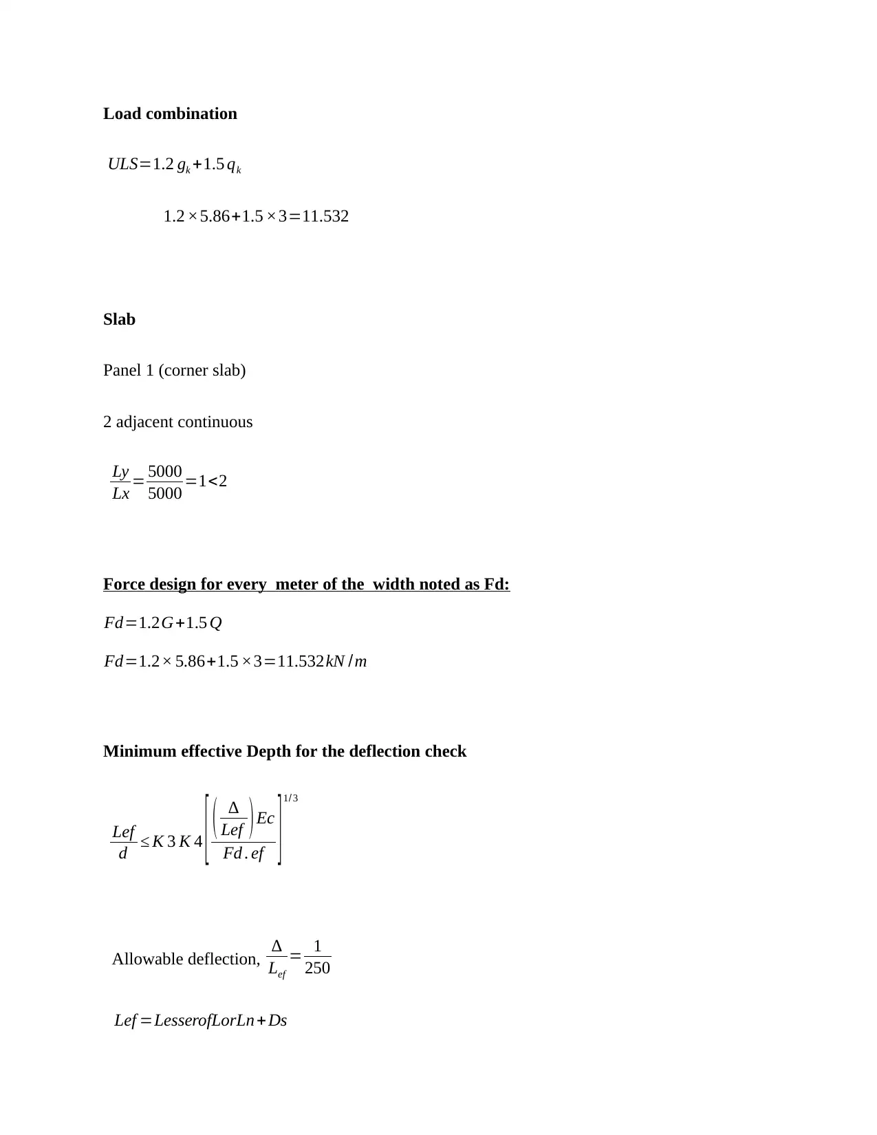
Load combination
ULS=1.2 gk +1.5 qk
1.2 ×5.86+1.5 ×3=11.532
Slab
Panel 1 (corner slab)
2 adjacent continuous
Ly
Lx = 5000
5000 =1<2
Force design for every meter of the width noted as Fd:
Fd=1.2G+1.5 Q
Fd=1.2× 5.86+1.5 ×3=11.532kN /m
Minimum effective Depth for the deflection check
Lef
d K 3 K 4 [ (
Lef )Ec
Fd . ef ]1/ 3
Allowable deflection,
Lef
= 1
250
Lef =LesserofLorLn +Ds
Document Page
¿ Lesserof 50004700
Lef =4700 mm
k cs=21.2 Asc
Ast
0.8 say 2.0 Cl .8 .5 .3.2
ψs =0.7 , ψ1=0.4 (Building type-Office) From AS 1170.0:2002 Cl.4.2.2 –
Effective design service Load, F¿= ( 1.0+kcs ) g+(ψs +k cs ψ1 ) q Cl.8.5.3.2
( 1.0+2.0 ) ×5.86+ ( 0.7+2.0 ×0.4 ) ×3=22.08 kN /m2
k3 =1.0 For two way slab
k 4=2.95
Ec=30100 caseof f ' c=32 MPa
d Lef
k3 k 4
3
Ec (
Lef )
F¿
= 4700
1.0× 2.95
3
30100 × 1
250
22.08 × 103
=90.5 mm
Effective depth, d= Dcover 0.5 main ¯diameter
d=200200.5 ×12 where cover (A1) = 20mm, main bar=12mm
dx=200206=174 mm
d y=17412=152 mm
d x , d y <90.5 mm Acceptable
Document Page
Moments
Ly/Lx =1.0
M*x = β 1 Fd Lx2 Cl.6.10.3.2
M*y = β 1 Fd Lx2
Coefficient βx=0.035
β y=0.035
Positive moment
M x
¿=0.035× 11.532× 52=10.09 kNm
M y
¿ =0.035 ×11.532 ×52=10.09 kNm
Negative moment (supports ) Cl.6.10.3.2 (B & C)
Interior support Mx=1.33 × 10.09=13.42 kNm
Exterior support M x=0.5× 10.09=5.045 kNm
Bending design
ξ= α2 f 'c
f sy
α2=1.00.003 f '
c
1.00.003× 32=0.904 say 0.85
tabler-icon-diamond-filled.svg

Paraphrase This Document

Need a fresh take? Get an instant paraphrase of this document with our AI Paraphraser
Document Page
γ=1.050.007 f '
c
1.050.007 ×32=0.91 say 0.85
assum ing =0.8
ξ= α2 f 'c
f sy
=0.85 × 32
500 =0.0544
pt =ξ ξ2 2 ξM
ϕb d2 f sy
Bottom
In the x- direction d x=174 mm
pt =0.0544 0.05442 2 ×0.0544 × 10.09× 106
0.85 ×1000 ×1742 × 500 =0.00078
In the y-direction d=152mm
pt =0.0544 0.05442 2× 0.0544 ×10.09 ×106
0.85 ×1000 ×1522 ×500 =0.0001
Top
In the x-direction
pt =0.0544 0.05442 2 ×0.0544 × 13.42× 106
0.85 ×1000 ×1742 × 500 =0.001
In the y-direction
pt =0.0544 0.05442 2× 0.0544 ×5.045 ×106
0.85 ×1000 ×1522 ×500 =0.0005
Document Page
ptmin =0.2 ( D
d )2 f 'cs
f sy
ptmin =0.2 ( 200
174 )
2 0.6 × 32
500 =1.793 ×10³
pt < ptmin use ptmin
In the x-direction
Ast= ptmin ×bd 1.793 ×103 ×1000 ×174=312 mm2 /m
provide N 12 @340 mm spacing340 m m2 /m
Checking spacing Cl.9.4.1b
Spacing ¿ Lesserof [ 2 D ; 300 ] mm
¿ Lesserof [400 ; 300]
Therefore use minimum spacing of 300 mm
provide N 12 @300 mm spac ing 367 mm2 /m
Therefore the spacingis okCheck the transverse steel for cracking control
In the y-direction
Ast= ptmin ×bd 1.793 ×103 ×1000 ×152=273 mm2 /m
provid e N 12 @ 400mm spacing 275m m2 /m
Document Page
Checking spacing Cl.9.4.1b
Spacing ¿ Lesserof [ 2 D ; 300 ] mm
¿ Lesserof [400 ; 300]
Therefore, use minimum spacing of 300 mm
provide N 12 @300 mm spacing367 m m2 /m
Therefore the spacingis okCheck the transverse steel for cracking control
Location direction pt Ast N12@ s Ast actual position
Supports X 1.793 ×10³ 312 300 367 top
Mid-
region
X 1.793 ×10³ 312 300 367 bottom
supports Y 1.793 ×10³ 273 300 367 top
Mid-
region
Y 1.793 ×10³ 273 300 367 bottom
Check shear
V* = LyFd
2 = 5 ( 11.532 )
2 =28.83 KN
Vuc=β 1 β 2 β 3 bvd 0 fcv ( Ast
bvdo )
1 /3
Cl.8.2.7
β 2=β 3=1
tabler-icon-diamond-filled.svg

Paraphrase This Document

Need a fresh take? Get an instant paraphrase of this document with our AI Paraphraser
Document Page
do=200206=174 mm β 1=1.1 (1.6 do
1000 ) 1.1
β 1=1.1 (1.6 174
1000 )=1.67>1.1
bv=1000 mm
Ast = 367 mm2/m
f ' cv = ( f ' c )
1
3 = ( 32 )
1
3 =3.17 MPa< 4 MPa
Vuc=1.59 ×1.0 × 1.0× 1000× 154 ×3.17 ( 367
1000 ×154 )1
3 =103.8 kN
0.5 Vuc=0.5 ×0.7 × 103.8=36.33 kN =0.7 Table 2.2.2
Vuc=¿36.33 KN¿ V¿ 28.83 kN
Therefore, no shear reinforcement required.
Slab
Panel 2 (edged slab)
2short edge discontinuous
Ly
Lx = 5000
5000 =1<2 Two way slab
Document Page
Effective depth, d= Dcover 0.5 main ¯diameter
d=200200.5 ×12 where cover (A1) = 20mm, main bar=12mm
design force per meter width, Fd:
Fd=1.2G+1.5 Q
Fd=1.2× 5.86+1.5 ×3=11.532kN /m
Minimum effective Depth for the deflection check
Lef
d K 3 K 4 [ (
Lef )Ec
Fd . ef ]1/ 3
Allowable deflection,
Lef
= 1
250 Table 2.3.2
Lef =LesserofLorLn +Ds
¿ Lesserof 50004700
Lef =4700 mm
k cs=21.2 Asc
Ast
0.8 say 2.0 Cl .8 .5 .3.2
ψs =0.7 , ψ1=0.4 (Office building) From AS 1170.0:2002 Cl.4.2.2 – Table 4.1
Effective design service Load, F¿= ( 1.0+kcs ) g+(ψs +k cs ψ1 ) q Cl.8.5.3.2
chevron_up_icon
1 out of 57
circle_padding
hide_on_mobile
zoom_out_icon
[object Object]