Project: Designing a Network Solution for SSM Australia (AusNet)
VerifiedAdded on 2020/04/01
|22
|6191
|492
Project
AI Summary
This project report details the network solution designed for Seven Star Motors (SSM) Australia, a company with branches across Australia. The project, undertaken by AusNet, involves designing a network that can accommodate a 50% growth in IP requirements over the next five years. The report covers the functional and non-functional requirements of the network, the network topology design (including bus, ring, star, and hybrid topologies), and the configuration of various network elements. It includes detailed configurations for Sydney head office, basic configurations, switching configurations, routing protocols, NAT, security measures like SSH and port security, and the use of a leased line. The network is tested using the GNS3 emulation platform before deployment. The report also considers the security aspects of the network, including firewall implementation and data security measures. The project aims to provide a robust and scalable network infrastructure for SSM Australia, supporting its business operations and future growth. It provides a comprehensive overview of network design principles and implementation strategies.
Paraphrase This Document
Need a fresh take? Get an instant paraphrase of this document with our AI Paraphraser

Executive Summary
SSM Australia is planning to incorporate a network set up configuration within their premises.
Working for the AusNet networking solution provider, the team is asked to design a network
solution for the requirements specified by the Seven Star Motors (SSM) Australia and test it using
GNS3 emulation platform before deploying the real network and document the specifications.
Contents
Introduction...........................................................................................................................................3
Requirements for branches – Functional / non functional....................................................................3
Topology – Design.................................................................................................................................4
Design a network solution.....................................................................................................................4
Sydney – Head office.............................................................................................................................6
Configurations: Basic configuration.......................................................................................................8
Switching Configuration........................................................................................................................9
Routing Protocols................................................................................................................................10
NAT..................................................................................................................................................12
Restricted Cone NAT....................................................................................................................12
Port-restricted cone based NAT...................................................................................................13
Symmetric NAT............................................................................................................................14
Leased line.......................................................................................................................................15
Security (SSH and Port Security)..........................................................................................................15
Conclusions..........................................................................................................................................16
References...........................................................................................................................................17
⊘ This is a preview!⊘
Do you want full access?
Subscribe today to unlock all pages.
Trusted by 1+ million students worldwide
Introduction
SSM Australia maintains, hires out, buys and sells new and used premium branded motor vehicles in
Australia. The head office of the company is situated in Sydney. The branches are located in
Melbourne, Perth and Brisbane. Company wants to implement a network that can support a
potential growth over the next five years and they have to hire AusNet in order to layout the
network with an expectation of 50% growth of current IP requirements.
Currently there are 125 employees at department of Sales and Hire, 45 employees in department of
Marketing, 20 employees within department of Vehicle Maintenance, 25 employees at the
department of Business Administration and 5 employees at department of Site Security by providing
their service to the head office which is also stationed in Sydney (Akyildiz Melodia & Chowdhury,
2008). All members of the department within Site Security required accessing the entire network via
a wireless LAN at each site. Company has their 20 employees working for the Technical Support
Group, 5 employees at each site. Sydney head office also has hosts the server farm for the network.
These servers are containing in web servers and file servers from which it carries company sensitive
information.
Requirements for branches – Functional / non functional
The connection between the nodes and the bus cable are known as drop line. It is very use to
understand and install also. It requires very less number of cables and inexpensive. It is very slow
and traffic is so high. The next one is the ring topology where the nodes are connected in the ring or
circular form. All the computers are connected in the form of circle. Every computer will act as a
repeater in the system. Here we cannot see any termination as the topology is in the form of ring.
The hardware requirement is very less. The troubleshooting is very difficult in this system. If one
computer is troubled then entire system will collapse. It is not easy to add or removes a computer
from the system. The next topology is star topology, where devices are connected with cable to a
centralised hub (Alabady, 2008). The packets of data are transferred to other computer through a
hub. These require huge number of cables. If hub fails entire system fails. This is very costly. The next
one is the hybrid topology. The hybrid topology is combination of all topology. The work efficiency is
high and the traffic is maintained properly. Here the hardware complexity is there.
Topology – Design
The topology is the way how the connections are made in the network. The first type of connection
is the point to point connection. The best example of this kind is the computers connecting with the
Paraphrase This Document
Need a fresh take? Get an instant paraphrase of this document with our AI Paraphraser
modem in both the direction. The next kind of example is the work stations connected in parallel
through same cable. In point to point communication there are three types of connections. They are
simplex, half duplex and full duplex. The simplex connection is the basic connection in which point
can only transmit the data or receive the data. The next one is the half duplex. The half duplex is one
which the data can be transmitted and received in both the ways. But it cannot be done
simultaneously. It can do one operation at a time only. When it is transmitting data it will not
receive, similarly the opposite also. The next one is the full duplex mode. The full duplex mode is one
which data can be transmitted and received simultaneously. This is the fastest way of
communication. The next one is the multipoint communication. In this three or more devices are
connected in the same line. The best multi point topologies are bus topology, ring topology and the
mesh topology (Ali & Alabady, 2007). The bus topology is one which has one cable and this called as
trunk. This truck will help to transfer the packets of data to all computers connected in the bus
network. Generally the bus topology is called as the passive topology. This is suitable for very less
computers. When the number of computers added the network will not work properly. The number
of computers must be limited. There should be terminators at the end of the terminals to avoid the
signal bounce back. The length of the bus can be increased by using barrel connectors. The signals
must be regenerated and for this function some repeaters are used. This bus network is used for the
temporary purpose. It is not used for the long term purpose. It can be limited for 10 people. If the
cable has problem then the entire system will not function. Hence it is not suitable for long term
basis (Downes, Rad & Aghajan, 2006).
Design a network solution
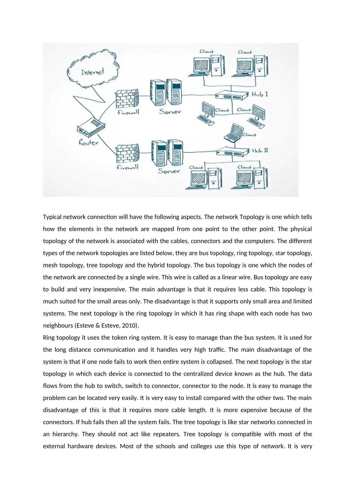
Typical network connection will have the following aspects. The network Topology is one which tells
how the elements in the network are mapped from one point to the other point. The physical
topology of the network is associated with the cables, connectors and the computers. The different
types of the network topologies are listed below, they are bus topology, ring topology, star topology,
mesh topology, tree topology and the hybrid topology. The bus topology is one which the nodes of
the network are connected by a single wire. This wire is called as a linear wire. Bus topology are easy
to build and very inexpensive. The main advantage is that it requires less cable. This topology is
much suited for the small areas only. The disadvantage is that it supports only small area and limited
systems. The next topology is the ring topology in which it has ring shape with each node has two
neighbours (Esteve & Esteve, 2010).
Ring topology it uses the token ring system. It is easy to manage than the bus system. It is used for
the long distance communication and it handles very high traffic. The main disadvantage of the
system is that if one node fails to work then entire system is collapsed. The next topology is the star
topology in which each device is connected to the centralized device known as the hub. The data
flows from the hub to switch, switch to connector, connector to the node. It is easy to manage the
problem can be located very easily. It is very easy to install compared with the other two. The main
disadvantage of this is that it requires more cable length. It is more expensive because of the
connectors. If hub fails then all the system fails. The tree topology is like star networks connected in
an hierarchy. They should not act like repeaters. Tree topology is compatible with most of the
external hardware devices. Most of the schools and colleges use this type of network. It is very
⊘ This is a preview!⊘
Do you want full access?
Subscribe today to unlock all pages.
Trusted by 1+ million students worldwide
difficult to configure. Mesh topology is one which each node is connected in the model of a network.
Implementing the mesh is very difficult and an expensive process. It can transfer the data in multiple
paths. They follow some algorithms for the data transfer in the shortest path and the fastest possible
way. The main advantage is that it has very less traffic problems. It has multiple links in which the
data is transferred in best possible path. Here the disadvantage is that it has mesh of wiring in which
it finds difficulty in managing the wire. The installation process is very difficult and the cables are
very costly. The hybrid topology is mixture one more topologies. It is extremely flexible but its is very
expensive at the same time (Ahmed, Namal, Ylianttila, & Gurtov, 2015).
The network configuration is a process in which the data flow is organized. The network
configuration allots the data flow through the hardware and software with supporting devices and
the components. The network configuration will gives the IP address for the system to get and send
the data through a router. The router configuration is done for the data passing. The next one is the
host configuration in which the host computer is configured. The next type is the software
configuration in which the network software’s are configured. The data is transferred in terms of the
packets. The two types of switching is used for the data transmission. They are circuit switching and
the packet switching. The circuit switching is a continuous data transfer. The data is transferred with
high data rates as the data flow is continuous. The packet switching is not a continuous data
transfer. In this data is transferred in the form of bits. All the packets are again collected at the
destination and arranged in the order. The data security can be maintained with help of installation
of antivirus in the computers to get rid of the virus and the online threats.
Sydney – Head office
The internet is accessed and first basic step is to connect the building through the routers. The
router is the primary aspect to access the internet. The router is connected to the Ethernet and the
power cables. Sometimes the router needs the bridge also. Then it is connected to the LAN, WAN
and the MAN cables for the connection set up. The best place for the router is the top of the home
so that it is not disturbed in any case. The router has few parts like the signal indicator which is used
to indicate the signals. The signal indicator has multiple colors. The basic colors are red, green, and
blue. This will help us to show the know the status of the data flow. The status may be like data flow,
no data, busy and not connected. WIFI is common in all the internet routers. The Wi-Fi indication
also helps us to know the data flow. Hence the Wi-Fi and signal indicators are integrated in many of
the new generation routers. The next part is the battery indication which shows the charging level of
the routers. The next common part of the router is the power button to on and off the router.
Generally USB ports are used for the data exchange purpose. Here the USB may be used for the
Paraphrase This Document
Need a fresh take? Get an instant paraphrase of this document with our AI Paraphraser
charging the router also. The firewall can be generally hardware or the software. This firewall will
help the end user to get protection from the internet malwares and virus. The working of the
hardware firewall is different from the software firewall. In the firewall only from the secured
websites only the data is exchanged. The rest of the other sites were not allowed. It also blocks the
unknown traffic also (Bukhari, Rehmani, & Siraj, 2015). The hardware firewalls are independent of
the computers and the internet. They filter the information from the internet and feed to the
computers and other internet accessing devices. They will examine the data and then if the data is
safe the data is allowed to access by the computers. The firewall will examine the data in terms of
the packets. The packets of the data are examined. There are two good advantages of the software
firewalls. The basic one is the that it can monitor the out going traffic. The second advantage is that
it can customize the data and the packets. Only disadvantage is that it can protect only one
computer. The servers are other important devices in the networks. Here the computer is first
request for the data from a page. Then the server will read the request and send the data from the
requested pages. There are many servers. The first server is the application server.
These servers are not necessarily part of the world wide web or internet. The next one is the catalog
servers which maintain the data in the form of tables, index and figures. This also contains the
shared files and the data of the computers in the network. The next server is the communication
server in which the data is communicated to the end user or not is checked. The data transfer must
be checked every time because it has to maintain the good communication with end users in other
words data must be successfully transfer to the systems. The next kind is the computing server,
which has much impact in the computations. It has much access over the CPU of the computer. The
next kind of server is the database servers. The data base servers are one which the data of the
network transferred over a place can be analysed by this servers. The next kind is the fax servers in
which the fax activities are maintained without the disturbance of the other servers. The next kind is
the file servers.
The files and the folders of the all the computers in the network are maintained from time to time.
This is one of the servers which helps in data management. The next server is the game server which
helps in the game aspects of the computer like gaming allocation for the multiple players and the
graphics of the players. The next one is the mail servers in which the mail access can be done in the
servers. The next server is the media server. The media server will have the audio and video files
management. This is used mostly in the multimedia application. The next one is the print server
which helps in the print applications. The next server is the sound server in which the sound of the
systems can be varied and analysed. Proxy server is the next kind of the server which acts as a
intermediate server between the client and the server. The web server is used to access the web
pages of the internet. The hardware requirement of the servers are the computer monitor,
processor, hardware USB ports, GUI, power shell. The operating system varied from the user
interests. The data from the server is shared with the clients with the help of hubs.
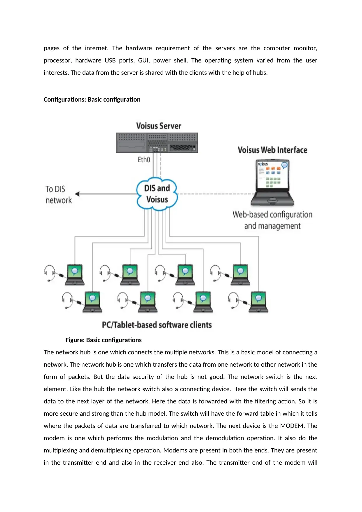
Configurations: Basic configuration
Figure: Basic configurations
The network hub is one which connects the multiple networks. This is a basic model of connecting a
network. The network hub is one which transfers the data from one network to other network in the
form of packets. But the data security of the hub is not good. The network switch is the next
element. Like the hub the network switch also a connecting device. Here the switch will sends the
data to the next layer of the network. Here the data is forwarded with the filtering action. So it is
more secure and strong than the hub model. The switch will have the forward table in which it tells
where the packets of data are transferred to which network. The next device is the MODEM. The
modem is one which performs the modulation and the demodulation operation. It also do the
multiplexing and demultiplexing operation. Modems are present in both the ends. They are present
in the transmitter end and also in the receiver end also. The transmitter end of the modem will
processor, hardware USB ports, GUI, power shell. The operating system varied from the user
interests. The data from the server is shared with the clients with the help of hubs.
Configurations: Basic configuration
Figure: Basic configurations
The network hub is one which connects the multiple networks. This is a basic model of connecting a
network. The network hub is one which transfers the data from one network to other network in the
form of packets. But the data security of the hub is not good. The network switch is the next
element. Like the hub the network switch also a connecting device. Here the switch will sends the
data to the next layer of the network. Here the data is forwarded with the filtering action. So it is
more secure and strong than the hub model. The switch will have the forward table in which it tells
where the packets of data are transferred to which network. The next device is the MODEM. The
modem is one which performs the modulation and the demodulation operation. It also do the
multiplexing and demultiplexing operation. Modems are present in both the ends. They are present
in the transmitter end and also in the receiver end also. The transmitter end of the modem will
⊘ This is a preview!⊘
Do you want full access?
Subscribe today to unlock all pages.
Trusted by 1+ million students worldwide
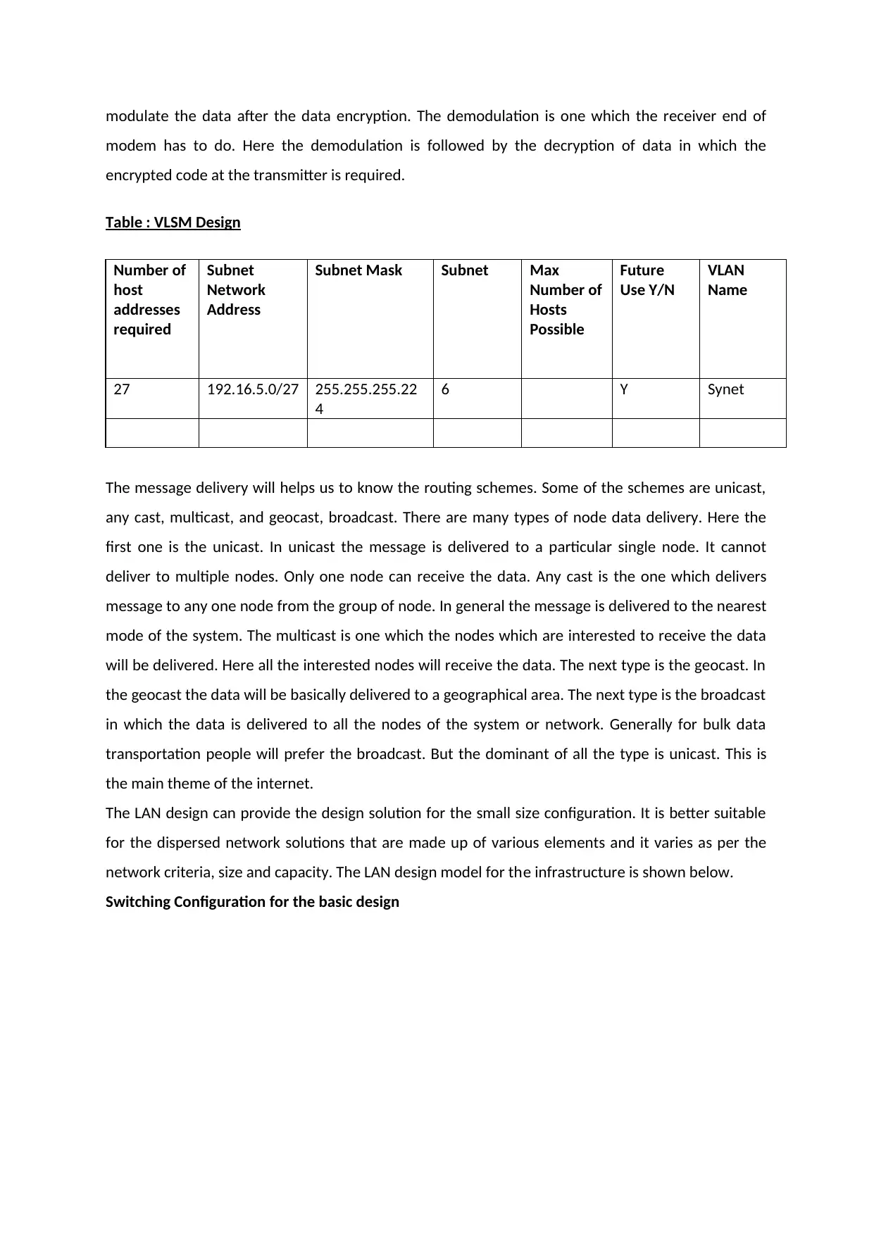
modulate the data after the data encryption. The demodulation is one which the receiver end of
modem has to do. Here the demodulation is followed by the decryption of data in which the
encrypted code at the transmitter is required.
Table : VLSM Design
Number of
host
addresses
required
Subnet
Network
Address
Subnet Mask Subnet Max
Number of
Hosts
Possible
Future
Use Y/N
VLAN
Name
27 192.16.5.0/27 255.255.255.22
4
6 Y Synet
The message delivery will helps us to know the routing schemes. Some of the schemes are unicast,
any cast, multicast, and geocast, broadcast. There are many types of node data delivery. Here the
first one is the unicast. In unicast the message is delivered to a particular single node. It cannot
deliver to multiple nodes. Only one node can receive the data. Any cast is the one which delivers
message to any one node from the group of node. In general the message is delivered to the nearest
mode of the system. The multicast is one which the nodes which are interested to receive the data
will be delivered. Here all the interested nodes will receive the data. The next type is the geocast. In
the geocast the data will be basically delivered to a geographical area. The next type is the broadcast
in which the data is delivered to all the nodes of the system or network. Generally for bulk data
transportation people will prefer the broadcast. But the dominant of all the type is unicast. This is
the main theme of the internet.
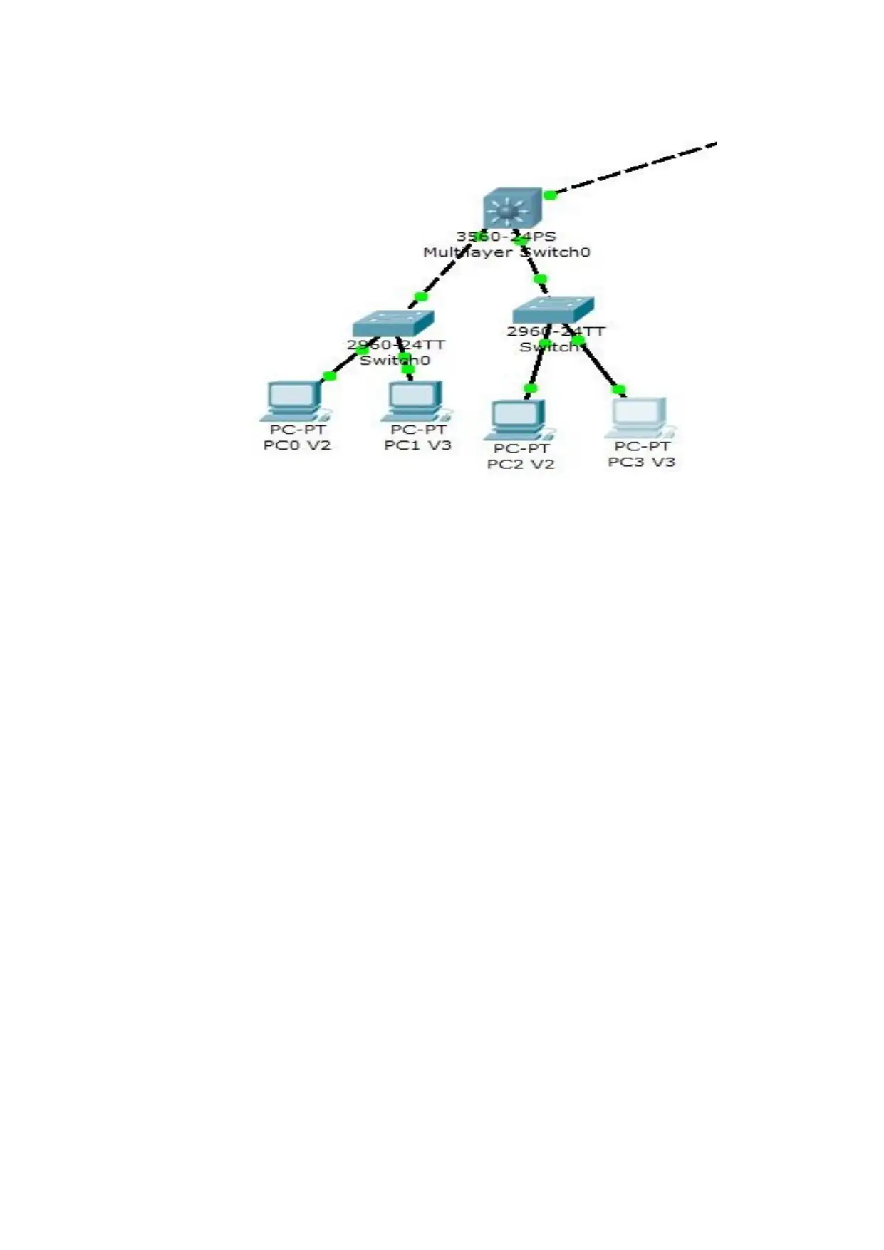
The LAN design can provide the design solution for the small size configuration. It is better suitable
for the dispersed network solutions that are made up of various elements and it varies as per the
network criteria, size and capacity. The LAN design model for the infrastructure is shown below.
Switching Configuration for the basic design
modem has to do. Here the demodulation is followed by the decryption of data in which the
encrypted code at the transmitter is required.
Table : VLSM Design
Number of
host
addresses
required
Subnet
Network
Address
Subnet Mask Subnet Max
Number of
Hosts
Possible
Future
Use Y/N
VLAN
Name
27 192.16.5.0/27 255.255.255.22
4
6 Y Synet
The message delivery will helps us to know the routing schemes. Some of the schemes are unicast,
any cast, multicast, and geocast, broadcast. There are many types of node data delivery. Here the
first one is the unicast. In unicast the message is delivered to a particular single node. It cannot
deliver to multiple nodes. Only one node can receive the data. Any cast is the one which delivers
message to any one node from the group of node. In general the message is delivered to the nearest
mode of the system. The multicast is one which the nodes which are interested to receive the data
will be delivered. Here all the interested nodes will receive the data. The next type is the geocast. In
the geocast the data will be basically delivered to a geographical area. The next type is the broadcast
in which the data is delivered to all the nodes of the system or network. Generally for bulk data
transportation people will prefer the broadcast. But the dominant of all the type is unicast. This is
the main theme of the internet.
The LAN design can provide the design solution for the small size configuration. It is better suitable
for the dispersed network solutions that are made up of various elements and it varies as per the
network criteria, size and capacity. The LAN design model for the infrastructure is shown below.
Switching Configuration for the basic design
Paraphrase This Document
Need a fresh take? Get an instant paraphrase of this document with our AI Paraphraser

The core layer deign for the ain site location depends on the number of the network users, speed of
the network and the overall network capacity. The core layer design is based on the ico atalyst 6500
series switches.
Implementation of LAN network Infrastructure
For the deployment of the design the mandatory steps and procedure that are required in the
implementation of VSS and its components are within the campus distribution and core. They are
VSS identifiers, virtual switch link, control panel, multi chassis there channel and dual active
detection and recovery system.
Switch ID
To deploy the switch ID each of the VSD supports the physical switches and help in the building of
logical virtual switch. The switch ID value is either 1 or 2. When any two physical chassis is clustered,
post VSS migration and management is done.
⊘ This is a preview!⊘
Do you want full access?
Subscribe today to unlock all pages.
Trusted by 1+ million students worldwide
1 out of 22
Related Documents


Your All-in-One AI-Powered Toolkit for Academic Success.
+13062052269
info@desklib.com
Available 24*7 on WhatsApp / Email
![[object Object]](/_next/static/media/star-bottom.7253800d.svg)
Unlock your academic potential
Copyright © 2020–2026 A2Z Services. All Rights Reserved. Developed and managed by ZUCOL.