WAN Design Document: Network Design for Toronto and Barrie Locations

Verified

Added on  2019/10/18

|2
|512
|222
Report
AI Summary
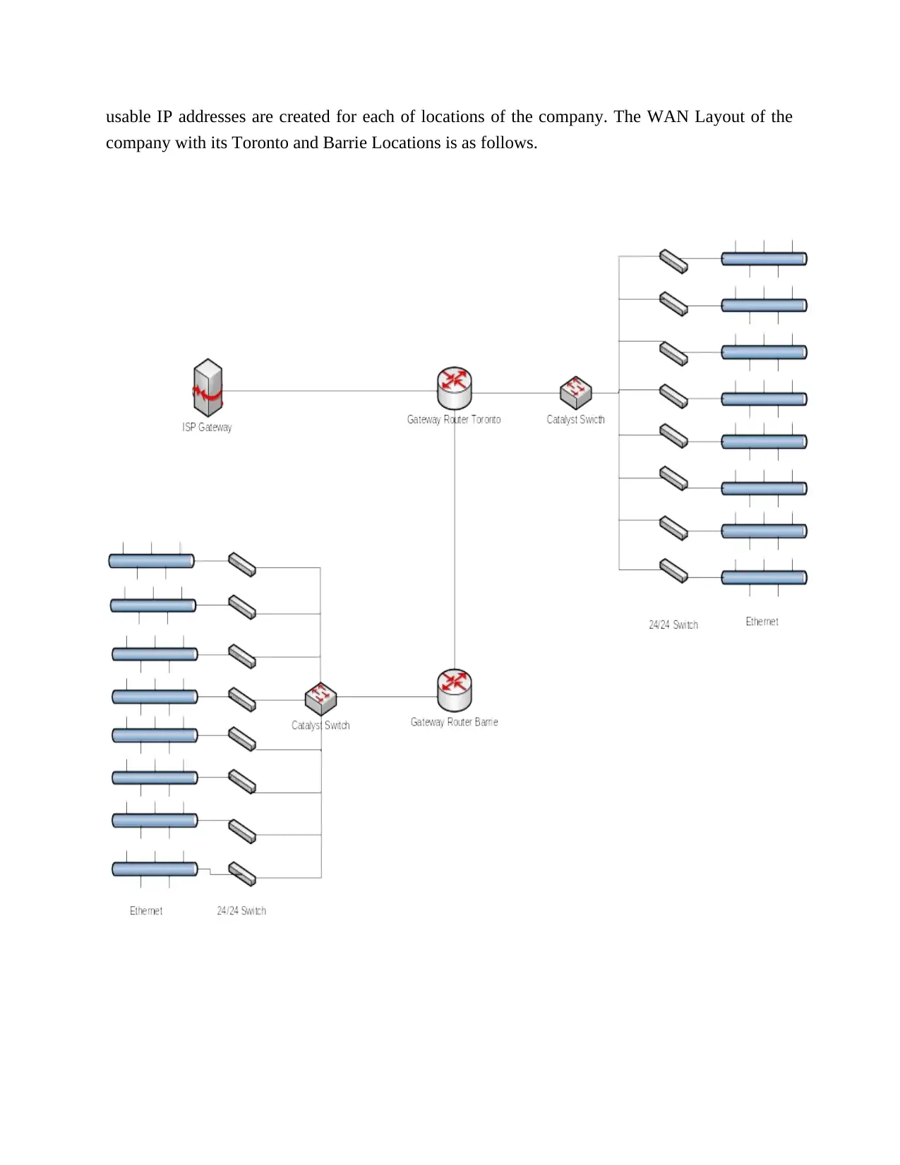
This report details the WAN design for a startup company with locations in Toronto and Barrie. The design includes the use of Cisco 2911 routers as gateway interfaces, 24/48 port switches, and FastEthernet connections for communication between devices. The report emphasizes the hierarchical and redundant network connectivity, facilitating data and voice communication. The design incorporates two public IP addresses, subnetted to provide IPv4 addressing for each location, ensuring 2000 usable IP addresses for each. The network layout also includes the integration of internet connectivity through an ISP. The document provides an overview of the network's topology and the key components involved in establishing a robust and scalable WAN infrastructure for the company.
Document Page
WAN Design Document
The large startup company requires designing a network for data and voice communication
between two locations such as Toronto and Barrie. At present the company has no network for
data and voice communication among the users of these two mentioned locations of company.
Each location of the company have the same number of users such as 2000 users. This needs a
Wide Area Network (WAN) communication system to enable the users of each location to
communicate data and voice from each other. The WAN network is required to be designed that
also include the Internet communication for users of each of the location. The connectivity
between the locations such as Toronto and Barrie needs the gateway interface such as gateway
routers for each of the location of the startup company. An another router is used to connect one
of the location gateway router with the Internet Service Provider to provide the Internet services
to both the location users of the company. The connection between the Gateway routers are high
speed Gig so that these gateway router must be specific in class to support high speed WAN
communication between two locations of the company. One Cisco Series 2911 router is taken up
for Toronto and one of same series router is taken up for Barrie to create the gateway interface
for both the company locations.
Further, there are 8 different offices at Toronto and Barrie Locations of the company. So, that 8
Cisco Catalyst Switches are used to make interface between the gateway router and 24/48 ports
switches for each of the location like Toronto and Barrie of the company. This creates the
hierarchical and redundant network connectivity between the location network devices and
computing nodes and IP phones. The connection between catalyst and 24/48 ports switches are
taken up by Fastethernet to support enough data rate to the computing nodes and IP phones of
users of Toronto and Barrie locations.
The connectivity between gateway routers of both locations of the company is taken up by
Gigabyte port and also with ISP by same port. The Computing nodes and IP phones are taken to
be connected with 24/48 port switches by fastethernet port connections. The assigned two public
IP addresses, 208.10.123.0 and 208.10.43.0 are taken to be subneting to provide the IPV4
addressing scheme for each of the Computing node and IP phone. In this regard 208.10.43.0 is
taken to make 8 subnets with required number of host addresses for Toronto location and
208.10.123.0 is taken to create 8 subnets for Barrie location of the company.
After subnetting, the IPV4 addresses are assigned to computing nodes of users of each of
department of each of the locations as per the requirement. As per the given requirement 2000
tabler-icon-diamond-filled.svg

Paraphrase This Document

Need a fresh take? Get an instant paraphrase of this document with our AI Paraphraser
Document Page
usable IP addresses are created for each of locations of the company. The WAN Layout of the
company with its Toronto and Barrie Locations is as follows.
chevron_up_icon
1 out of 2
circle_padding
hide_on_mobile
zoom_out_icon
[object Object]