STATCOM-Based Voltage Compensation in AC Transmission Systems

Verified

Added on  2022/11/18

|3
|950
|463
Report
AI Summary
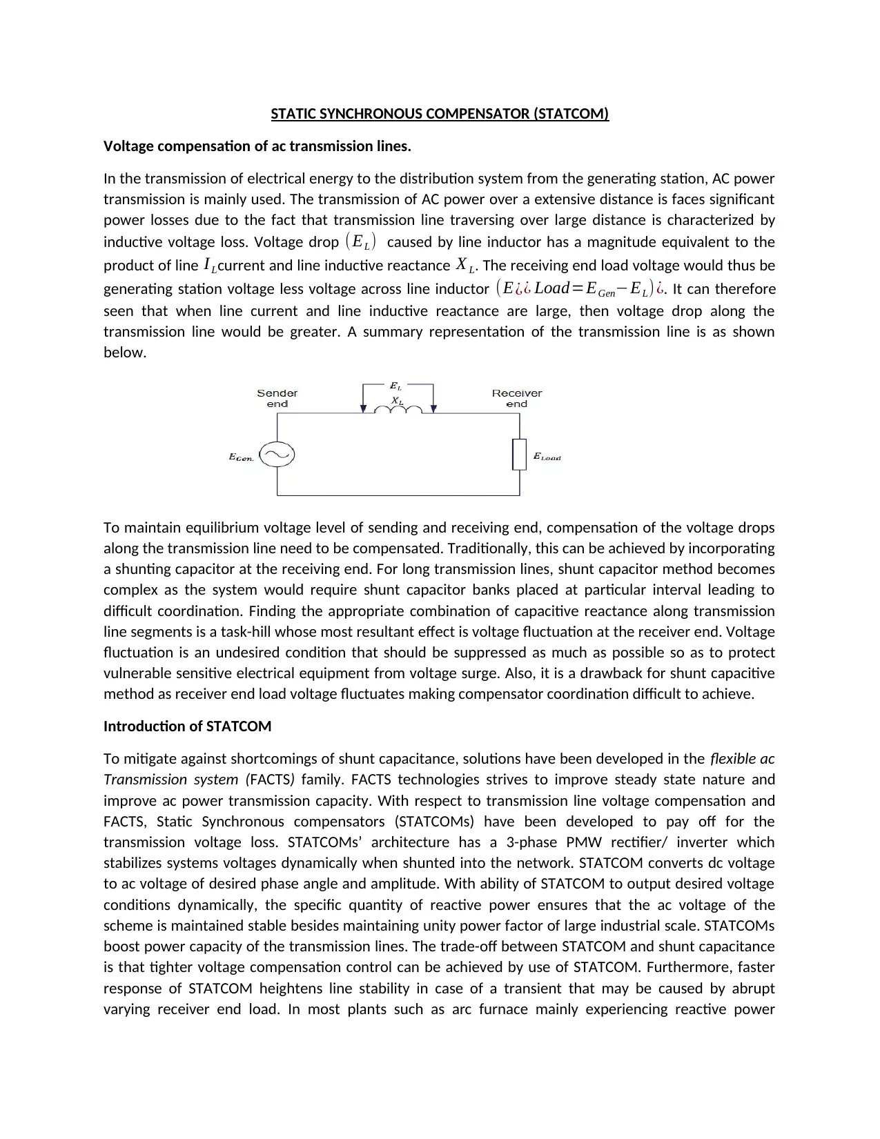
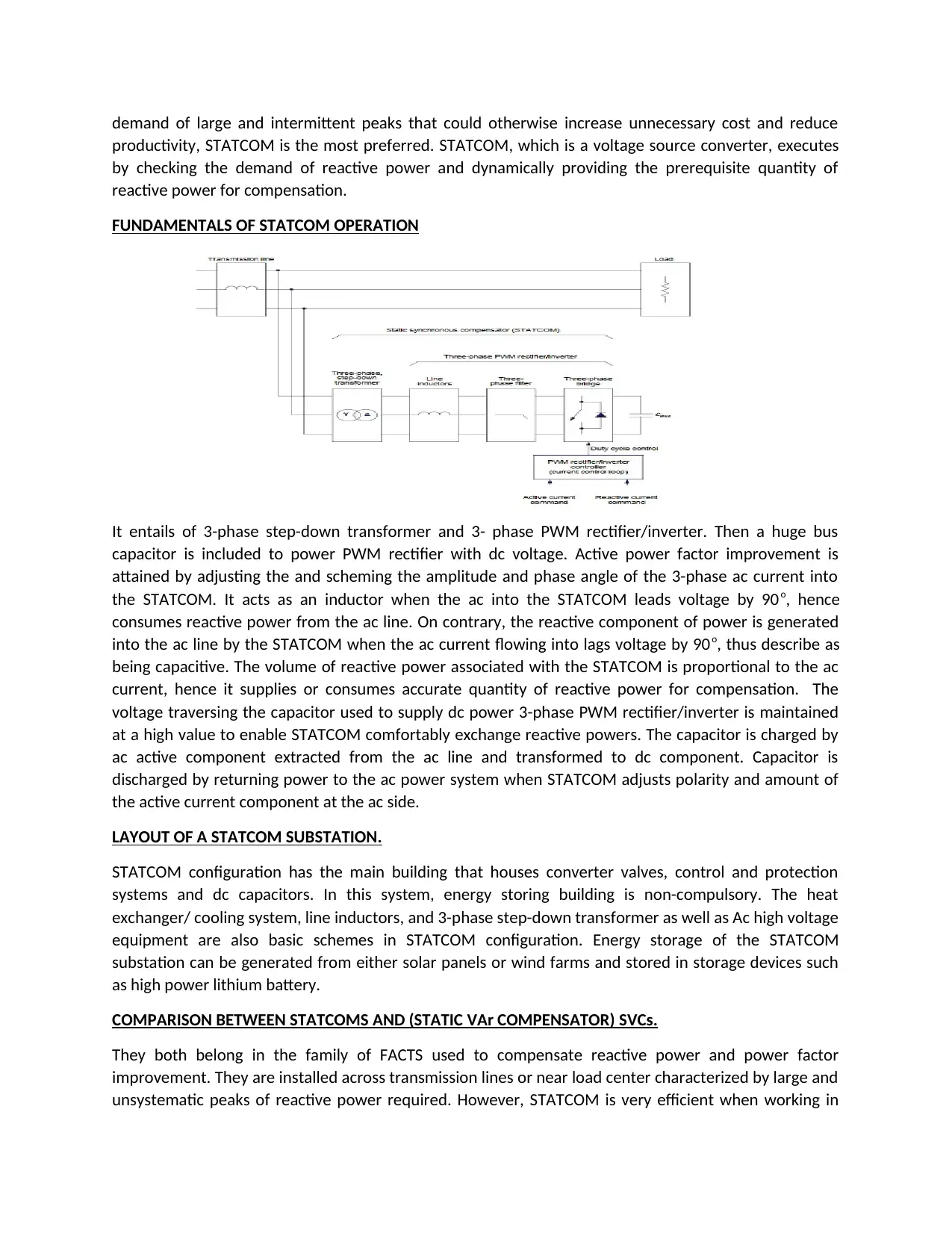
This report discusses the application of Static Synchronous Compensators (STATCOM) in AC transmission lines for voltage compensation. It highlights the limitations of traditional shunt capacitor methods and introduces STATCOM as a Flexible AC Transmission System (FACTS) technology to improve voltage stability and power transmission capacity. The report details the fundamentals of STATCOM operation, including its ability to dynamically control reactive power, maintain voltage stability, and improve power factor. It also covers the layout of a STATCOM substation, the comparison between STATCOMs and Static VAR Compensators (SVCs), and the advantages of STATCOM in under-voltage conditions and response time. The document emphasizes the role of STATCOM in mitigating voltage fluctuations and enhancing the overall efficiency of AC power transmission.
Document Page
STATIC SYNCHRONOUS COMPENSATOR (STATCOM)
Voltage compensation of ac transmission lines.
In the transmission of electrical energy to the distribution system from the generating station, AC power
transmission is mainly used. The transmission of AC power over a extensive distance is faces significant
power losses due to the fact that transmission line traversing over large distance is characterized by
inductive voltage loss. Voltage drop (EL) caused by line inductor has a magnitude equivalent to the
product of line I Lcurrent and line inductive reactance X L. The receiving end load voltage would thus be
generating station voltage less voltage across line inductor (E¿¿ Load=EGenEL)¿. It can therefore
seen that when line current and line inductive reactance are large, then voltage drop along the
transmission line would be greater. A summary representation of the transmission line is as shown
below.
To maintain equilibrium voltage level of sending and receiving end, compensation of the voltage drops
along the transmission line need to be compensated. Traditionally, this can be achieved by incorporating
a shunting capacitor at the receiving end. For long transmission lines, shunt capacitor method becomes
complex as the system would require shunt capacitor banks placed at particular interval leading to
difficult coordination. Finding the appropriate combination of capacitive reactance along transmission
line segments is a task-hill whose most resultant effect is voltage fluctuation at the receiver end. Voltage
fluctuation is an undesired condition that should be suppressed as much as possible so as to protect
vulnerable sensitive electrical equipment from voltage surge. Also, it is a drawback for shunt capacitive
method as receiver end load voltage fluctuates making compensator coordination difficult to achieve.
Introduction of STATCOM
To mitigate against shortcomings of shunt capacitance, solutions have been developed in the flexible ac
Transmission system (FACTS) family. FACTS technologies strives to improve steady state nature and
improve ac power transmission capacity. With respect to transmission line voltage compensation and
FACTS, Static Synchronous compensators (STATCOMs) have been developed to pay off for the
transmission voltage loss. STATCOMs’ architecture has a 3-phase PMW rectifier/ inverter which
stabilizes systems voltages dynamically when shunted into the network. STATCOM converts dc voltage
to ac voltage of desired phase angle and amplitude. With ability of STATCOM to output desired voltage
conditions dynamically, the specific quantity of reactive power ensures that the ac voltage of the
scheme is maintained stable besides maintaining unity power factor of large industrial scale. STATCOMs
boost power capacity of the transmission lines. The trade-off between STATCOM and shunt capacitance
is that tighter voltage compensation control can be achieved by use of STATCOM. Furthermore, faster
response of STATCOM heightens line stability in case of a transient that may be caused by abrupt
varying receiver end load. In most plants such as arc furnace mainly experiencing reactive power
tabler-icon-diamond-filled.svg

Secure Best Marks with AI Grader

Need help grading? Try our AI Grader for instant feedback on your assignments.
Document Page
demand of large and intermittent peaks that could otherwise increase unnecessary cost and reduce
productivity, STATCOM is the most preferred. STATCOM, which is a voltage source converter, executes
by checking the demand of reactive power and dynamically providing the prerequisite quantity of
reactive power for compensation.
FUNDAMENTALS OF STATCOM OPERATION
It entails of 3-phase step-down transformer and 3- phase PWM rectifier/inverter. Then a huge bus
capacitor is included to power PWM rectifier with dc voltage. Active power factor improvement is
attained by adjusting the and scheming the amplitude and phase angle of the 3-phase ac current into
the STATCOM. It acts as an inductor when the ac into the STATCOM leads voltage by 90 o, hence
consumes reactive power from the ac line. On contrary, the reactive component of power is generated
into the ac line by the STATCOM when the ac current flowing into lags voltage by 90o, thus describe as
being capacitive. The volume of reactive power associated with the STATCOM is proportional to the ac
current, hence it supplies or consumes accurate quantity of reactive power for compensation. The
voltage traversing the capacitor used to supply dc power 3-phase PWM rectifier/inverter is maintained
at a high value to enable STATCOM comfortably exchange reactive powers. The capacitor is charged by
ac active component extracted from the ac line and transformed to dc component. Capacitor is
discharged by returning power to the ac power system when STATCOM adjusts polarity and amount of
the active current component at the ac side.
LAYOUT OF A STATCOM SUBSTATION.
STATCOM configuration has the main building that houses converter valves, control and protection
systems and dc capacitors. In this system, energy storing building is non-compulsory. The heat
exchanger/ cooling system, line inductors, and 3-phase step-down transformer as well as Ac high voltage
equipment are also basic schemes in STATCOM configuration. Energy storage of the STATCOM
substation can be generated from either solar panels or wind farms and stored in storage devices such
as high power lithium battery.
COMPARISON BETWEEN STATCOMS AND (STATIC VAr COMPENSATOR) SVCs.
They both belong in the family of FACTS used to compensate reactive power and power factor
improvement. They are installed across transmission lines or near load center characterized by large and
unsystematic peaks of reactive power required. However, STATCOM is very efficient when working in
Document Page
under-voltage circumstances while SVC has a restricted performance in the same condition. Also,
STATCOM has a faster time response than SVC. STATCOM are very expensive to install despite their
smaller size as compared to SVC.
chevron_up_icon
1 out of 3
circle_padding
hide_on_mobile
zoom_out_icon
logo.png

Your All-in-One AI-Powered Toolkit for Academic Success.

Available 24*7 on WhatsApp / Email

[object Object]