ITEC7410 Software Engineering: State Transition Diagram of Oral B 5000
VerifiedAdded on 2023/04/20
|14
|1877
|328
Project
AI Summary
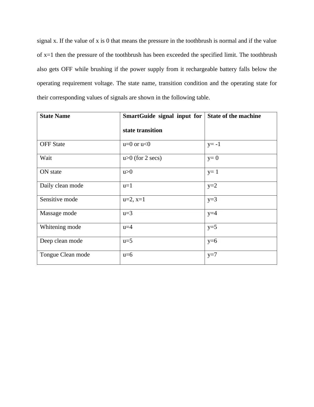
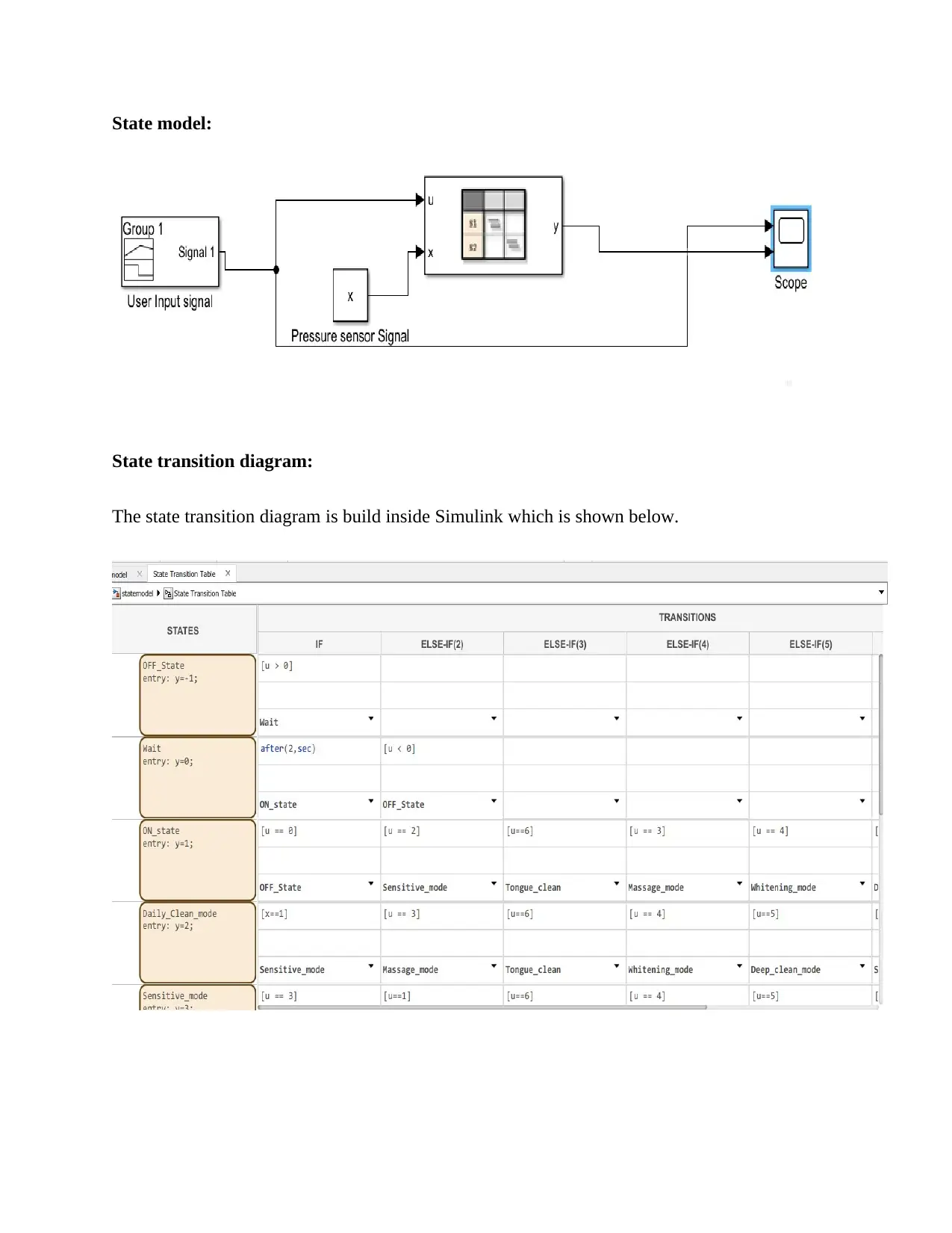
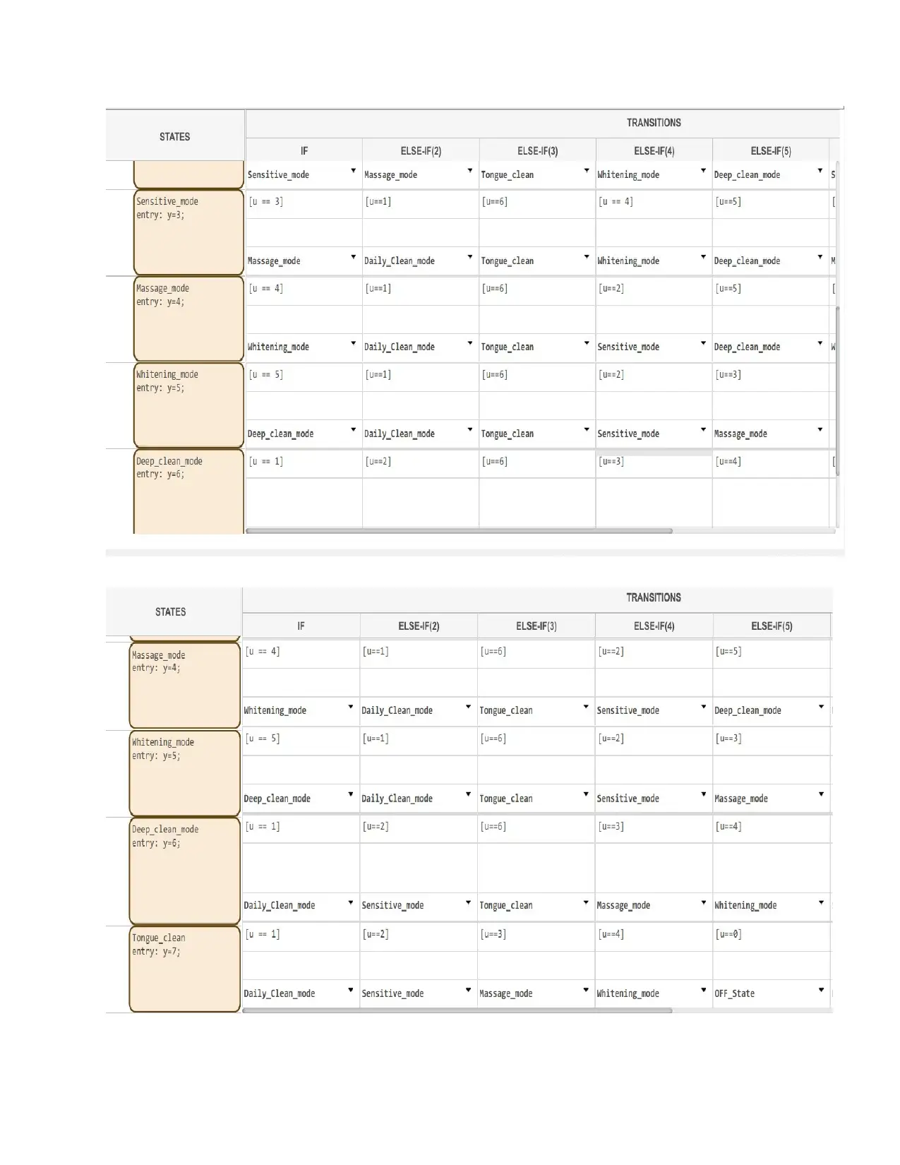
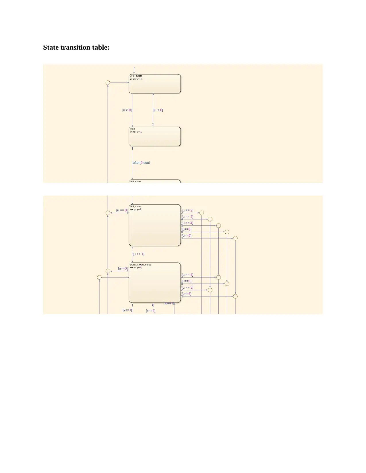
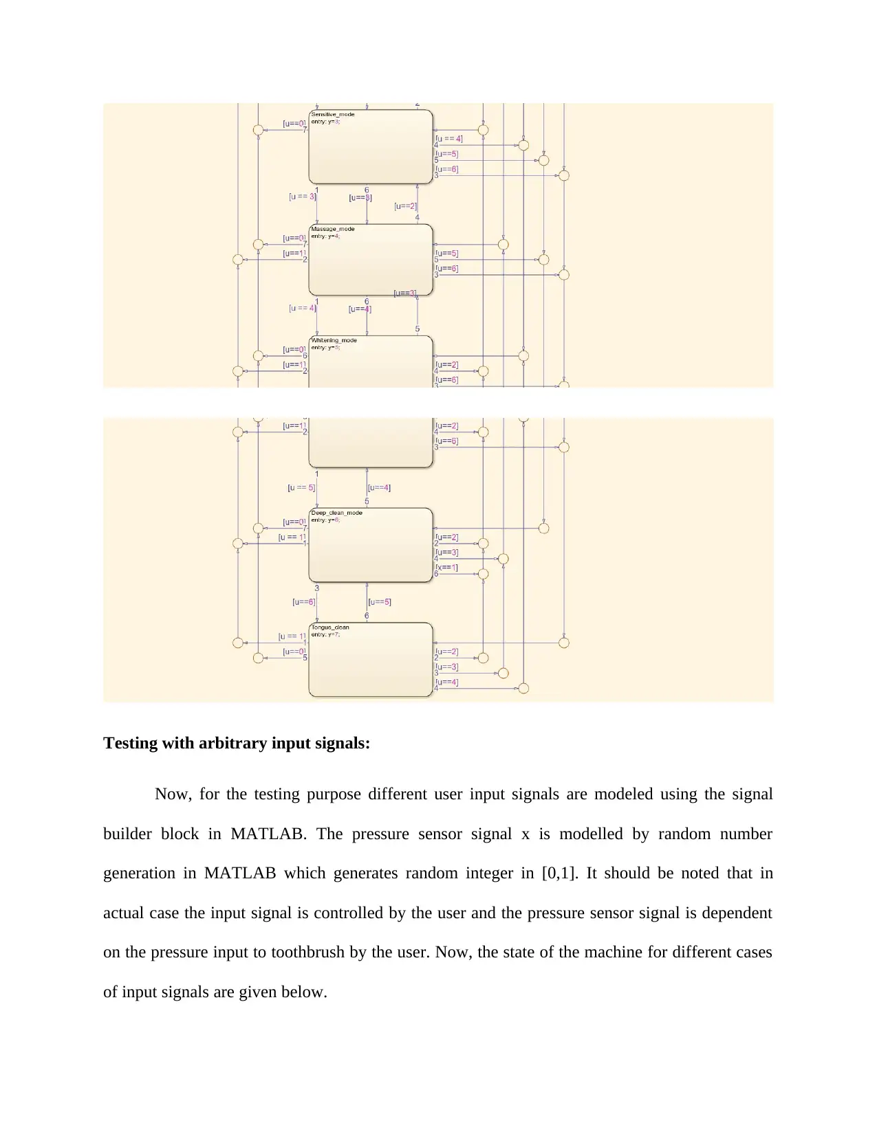
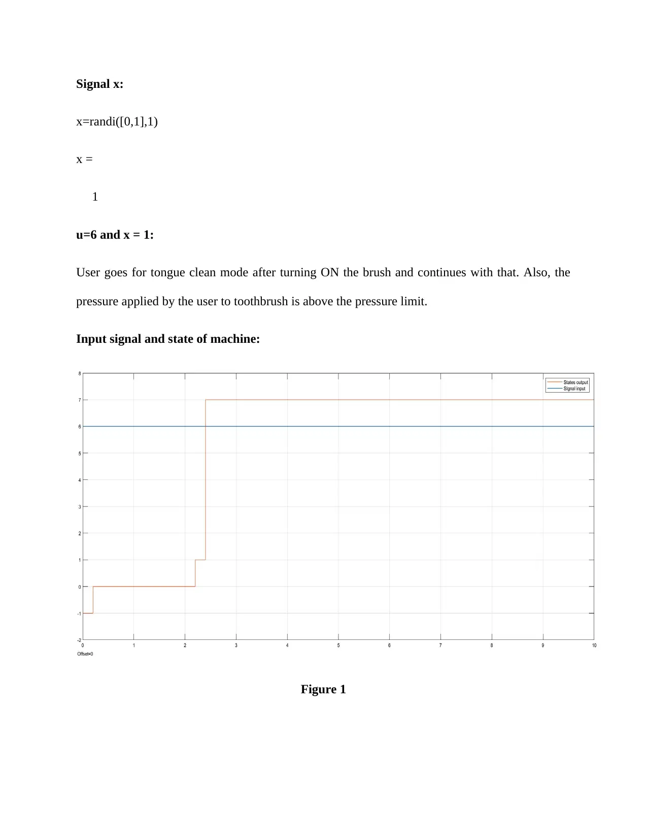
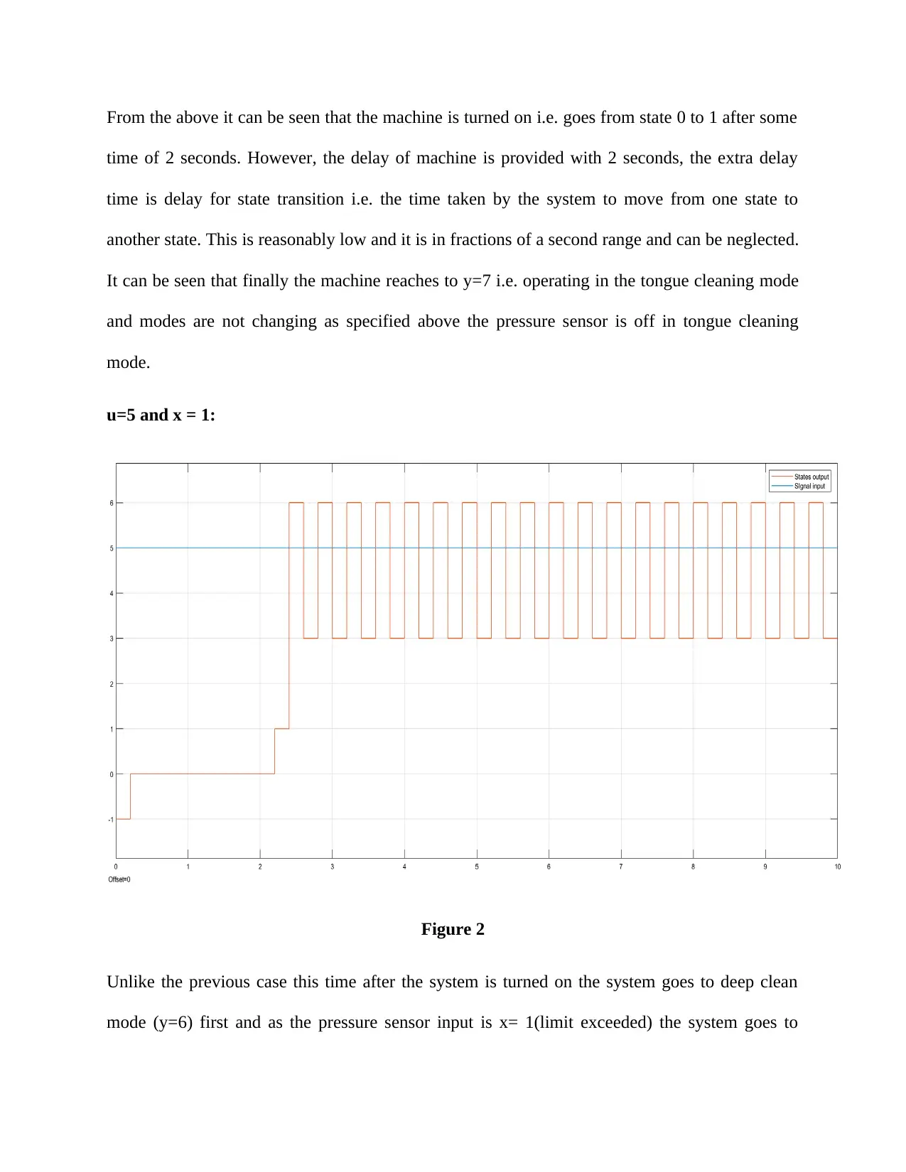
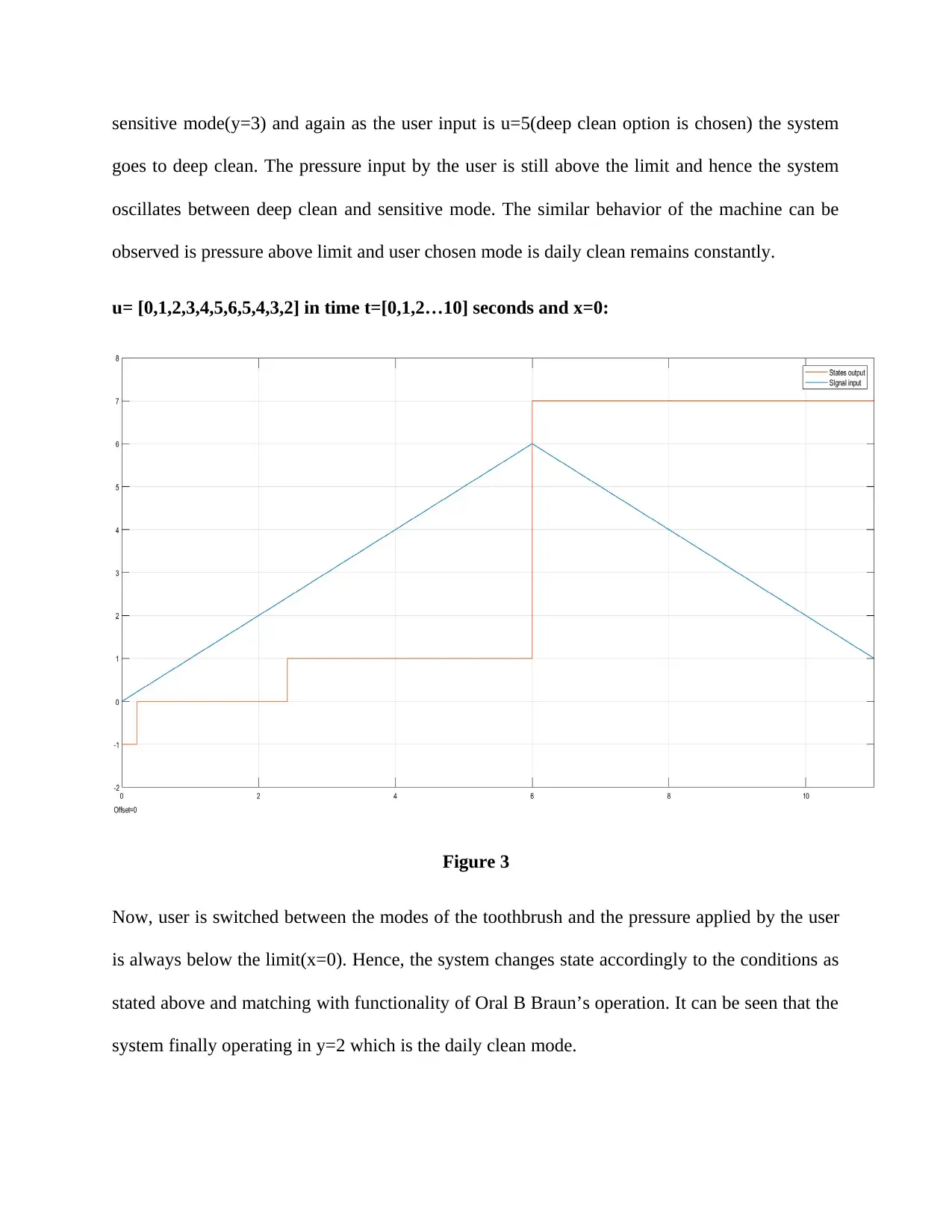
This assignment presents a state transition diagram for the Oral B 5000 Braun electric toothbrush, modeling its functionalities and interactions with the SmartGuide user interface. The assignment utilizes MATLAB and Simulink to create the diagram, illustrating the different states of the toothbrush (OFF, ON, various cleaning modes) and the transitions between them based on user input and pressure sensor readings. The document details the toothbrush's features, including its charging capabilities, timer adjustments, brushing feedback, and various cleaning modes (Daily clean, Massage, Sensitive, Whitening, Deep clean, and Tongue clean). The state transition diagram is created using Simulink, with user input signals (u) and pressure sensor signals (x) controlling the transitions between states. The assignment includes the state transition table, and testing with arbitrary input signals to demonstrate the operation of the toothbrush. The assignment concludes with a video transcript description and a conclusion summarizing the successful implementation of the state transition diagram, which accurately reflects the functionalities of the Oral B Braun 5000 electric toothbrush as described in its manual.

Student Name
Assignment 1
State transition diagram
Name of the Instructor
Date
Assignment 1
State transition diagram
Name of the Instructor
Date
Paraphrase This Document
Need a fresh take? Get an instant paraphrase of this document with our AI Paraphraser

Introduction:
The objective of this assignment is to develop a state chart diagram for the operation of
Oral B 5000 Braun electric toothbrush. The functionalities of the electric toothbrush is controlled
by installed SmartGuide user interface. Hence, the transition between the modes of the electric
toothbrush is modelled with the input signals from the SmartGuide system which is user
controlled and affected by some external condition like pressure input in the toothbrush. The
state transition diagram is basically an interchangeability of states based on particular input
conditions. In addition to the state diagram all the states of the machine and their functionality is
listed in the later section. The software chosen for modelling the state diagram of the machine is
MATLAB (more specifically Simulink) due to it simple and compact design and visually
attractive graph generation ability. The Oral B Braun electric toothbrush is recommended by
most of the dentists as it takes full care of the brushing operation of mouth and teeth and solves
almost every dental problem if used regularly in the prescribed manner.
Oral B Braun 5000 electric toothbrush Functionality & SmartGuide:
The main functions of the Oral B Braun electric toothbrush are listed below.
The electric toothbrush is chargeable and charging is very easy as it only requires to the
toothbrush handle of be plugged in into an electric outlet and once get fully charged it can
operate 1 to 2 days without charging.
The brushing timer can easily be adjusted by the user by the SmartGuide interface. The
user has the option to choose between the professional mode and 2- minute timer mode
and under each mode the brushing time can be increased or decreased using the count up
or count down button by user’s need.

The brushing feedback in real time is displayed to the user by the Bluetooth capability of
the electric toothbrush and the oral B app which can be installed in the any computer.
The toothbrush offers a total of 5 brushing modes and one tongue cleaning mode. The
user can switch between the modes after turning on the toothbrush. The brushing modes
are Daily clean mode, Massage mode, Sensitive mode, Whitening mode and Deep clean
mode.
One pressure sensor is also installed in the toothbrush which senses if pressure is
increased over a predefined value while brushing. This triggers a red bulb in the system
and a warning message is displayed in the SmartScreen. Also, if the brush is operating in
daily clean mode or deep clean mode then if pressure bulb glows then it brushing mode
automatically changes to sensitive mode. However, in other modes and in tongue
cleaning mode the pressure sensor remains deactivated.
Description of the state transition diagram:
Now, the electric toothbrush does not turn on as soon as the ON switch is pressed by the
user. It takes a delay of 2 seconds to activate all the components within the system and after that
the toothbrush is fully operational. After that user can choose any brushing mode and user can
continue with that or change according to their desire.
Hence, this can be modelled in MATLAB by using the states of the machine as described below.
The signal of the user which is converted by the SmartGuide to some specific values of signal u
for state transition is shown below. Also, the state in which the machine is operating is
represented by the signal y. The particular discrete values of u and y corresponds to their
transition condition and current state. Additionally, the signal generated by the pressure sensor
which changes the daily clean mode and deep clean mode to sensitive mode is modelled by the
⊘ This is a preview!⊘
Do you want full access?
Subscribe today to unlock all pages.

Trusted by 1+ million students worldwide

signal x. If the value of x is 0 that means the pressure in the toothbrush is normal and if the value
of x=1 then the pressure of the toothbrush has been exceeded the specified limit. The toothbrush
also gets OFF while brushing if the power supply from it rechargeable battery falls below the
operating requirement voltage. The state name, transition condition and the operating state for
their corresponding values of signals are shown in the following table.
State Name SmartGuide signal input for
state transition
State of the machine
OFF State u=0 or u<0 y= -1
Wait u>0 (for 2 secs) y= 0
ON state u>0 y= 1
Daily clean mode u=1 y=2
Sensitive mode u=2, x=1 y=3
Massage mode u=3 y=4
Whitening mode u=4 y=5
Deep clean mode u=5 y=6
Tongue Clean mode u=6 y=7
Paraphrase This Document
Need a fresh take? Get an instant paraphrase of this document with our AI Paraphraser

State model:
State transition diagram:
The state transition diagram is build inside Simulink which is shown below.
State transition diagram:
The state transition diagram is build inside Simulink which is shown below.

⊘ This is a preview!⊘
Do you want full access?
Subscribe today to unlock all pages.

Trusted by 1+ million students worldwide

State transition table:
Paraphrase This Document
Need a fresh take? Get an instant paraphrase of this document with our AI Paraphraser

Testing with arbitrary input signals:
Now, for the testing purpose different user input signals are modeled using the signal
builder block in MATLAB. The pressure sensor signal x is modelled by random number
generation in MATLAB which generates random integer in [0,1]. It should be noted that in
actual case the input signal is controlled by the user and the pressure sensor signal is dependent
on the pressure input to toothbrush by the user. Now, the state of the machine for different cases
of input signals are given below.

Signal x:
x=randi([0,1],1)
x =
1
u=6 and x = 1:
User goes for tongue clean mode after turning ON the brush and continues with that. Also, the
pressure applied by the user to toothbrush is above the pressure limit.
Input signal and state of machine:
Figure 1
x=randi([0,1],1)
x =
1
u=6 and x = 1:
User goes for tongue clean mode after turning ON the brush and continues with that. Also, the
pressure applied by the user to toothbrush is above the pressure limit.
Input signal and state of machine:
Figure 1
⊘ This is a preview!⊘
Do you want full access?
Subscribe today to unlock all pages.

Trusted by 1+ million students worldwide

From the above it can be seen that the machine is turned on i.e. goes from state 0 to 1 after some
time of 2 seconds. However, the delay of machine is provided with 2 seconds, the extra delay
time is delay for state transition i.e. the time taken by the system to move from one state to
another state. This is reasonably low and it is in fractions of a second range and can be neglected.
It can be seen that finally the machine reaches to y=7 i.e. operating in the tongue cleaning mode
and modes are not changing as specified above the pressure sensor is off in tongue cleaning
mode.
u=5 and x = 1:
Figure 2
Unlike the previous case this time after the system is turned on the system goes to deep clean
mode (y=6) first and as the pressure sensor input is x= 1(limit exceeded) the system goes to
Paraphrase This Document
Need a fresh take? Get an instant paraphrase of this document with our AI Paraphraser

sensitive mode(y=3) and again as the user input is u=5(deep clean option is chosen) the system
goes to deep clean. The pressure input by the user is still above the limit and hence the system
oscillates between deep clean and sensitive mode. The similar behavior of the machine can be
observed is pressure above limit and user chosen mode is daily clean remains constantly.
u= [0,1,2,3,4,5,6,5,4,3,2] in time t=[0,1,2…10] seconds and x=0:
Figure 3
Now, user is switched between the modes of the toothbrush and the pressure applied by the user
is always below the limit(x=0). Hence, the system changes state accordingly to the conditions as
stated above and matching with functionality of Oral B Braun’s operation. It can be seen that the
system finally operating in y=2 which is the daily clean mode.

Video Transcript description:
The final state transition diagram is formed by modifying the state diagram developed in
earlier section. The conditions for state transition can be viewed by double clicking the state
table block in Simulink. Now, inside the state transition table the states are defined in the first
column (States column). The toothbrush modes are modelled as its states which are Daily clean,
sensitive mode, Massage mode, whitening mode, deep clean mode and tongue clean mode. In
addition to these states OFF state, ON state and Wait state is provided in the model. The wait
state is there as the toothbrush takes the sometime (typically of 2 seconds) to initially all its
operations that is to move from OFF to ON state. Now, in the later columns define the state
transition conditions inside if and elseif statements. The state transition conditions are controlled
by the user input signal (u) and the pressure sensor signal(x). Now, if the input signal is too much
low i.e. the less than value to keep the circuit operational then machine goes to off State(u<0) as
in low voltage the circuit operation may be abnormal and can cause abnormal state change. The
value of x which is the random generated pressure signal (equivalent to the pressure signal input
by user modified into signal by SmartGuide interface) has produced 0 value or the pressure is
normal. The user input signal u= [0,1,2,3,4,5,6,5,4,3,2] in time t=[0,1,2…10] seconds is
generated in signal builder block in Simulink from custom signal option. Then finally the state
diagram is simulation with discrete solver option in Simulink for a duration of 11 seconds. Now,
the scope block in Simulink is opened and two graphs of state of machine and user input signal
can be found as given in Figure 3. Similarly, figure 1 and figure can be found when the user
input signal is constant (i.e. the user chooses only a specific toothbrush mode) and x=1 (pressure
applied to toothbrush by the user is always above the pressure limit). As specified in the Oral B
brush manual the daily clean mode and deep clean mode goes to sensitive mode when the
⊘ This is a preview!⊘
Do you want full access?
Subscribe today to unlock all pages.

Trusted by 1+ million students worldwide
1 out of 14
Related Documents

Your All-in-One AI-Powered Toolkit for Academic Success.
+13062052269
info@desklib.com
Available 24*7 on WhatsApp / Email
Unlock your academic potential
Copyright © 2020–2025 A2Z Services. All Rights Reserved. Developed and managed by ZUCOL.