ME1300 Statics Assignment: Engineering Systems & Static Equilibrium

Verified

Added on  2023/06/15

|7
|897
|359
Homework Assignment
AI Summary
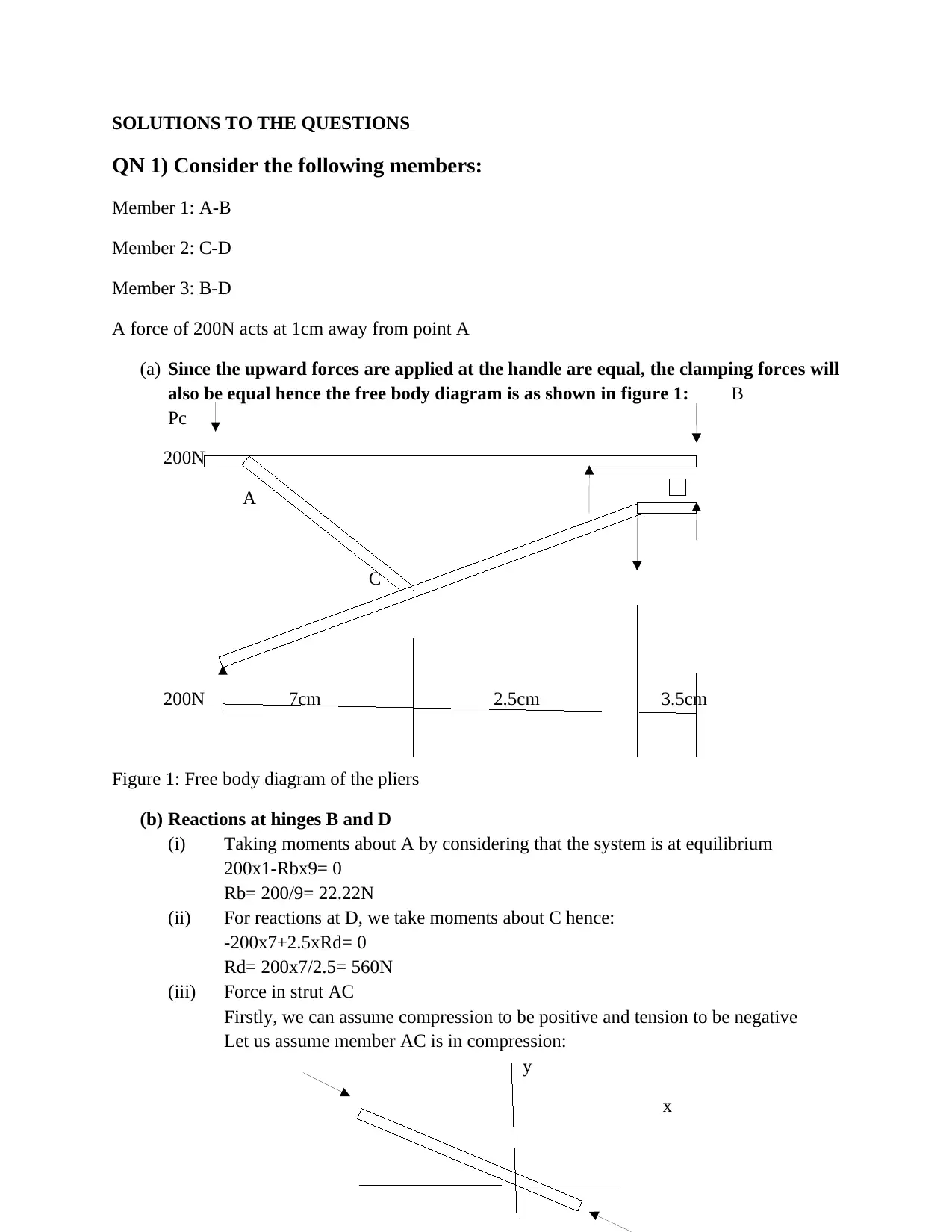
This document provides solutions to a statics assignment involving the analysis of engineering structures under static loads. It covers concepts such as free body diagrams, equilibrium equations, and the application of mathematical and engineering science methods to solve problems. The assignment includes questions related to clamping forces, reactions at hinges, strut forces, bending moment calculations, and shear force diagrams. Specific problems address the determination of reactions at supports, shear force and bending moment equations, and the analysis of forces in structural members. The solutions involve detailed calculations and explanations, demonstrating an understanding of static equilibrium principles and their application to engineering scenarios. Desklib provides a platform for students to access similar solved assignments and past papers for academic support.
tabler-icon-diamond-filled.svg

Contribute Materials

Your contribution can guide someone’s learning journey. Share your documents today.
Document Page
SOLUTIONS TO THE QUESTIONS
QN 1) Consider the following members:
Member 1: A-B
Member 2: C-D
Member 3: B-D
A force of 200N acts at 1cm away from point A
(a) Since the upward forces are applied at the handle are equal, the clamping forces will
also be equal hence the free body diagram is as shown in figure 1: B
Pc
200N
A
C
200N 7cm 2.5cm 3.5cm
Figure 1: Free body diagram of the pliers
(b) Reactions at hinges B and D
(i) Taking moments about A by considering that the system is at equilibrium
200x1-Rbx9= 0
Rb= 200/9= 22.22N
(ii) For reactions at D, we take moments about C hence:
-200x7+2.5xRd= 0
Rd= 200x7/2.5= 560N
(iii) Force in strut AC
Firstly, we can assume compression to be positive and tension to be negative
Let us assume member AC is in compression:
y
x
tabler-icon-diamond-filled.svg

Secure Best Marks with AI Grader

Need help grading? Try our AI Grader for instant feedback on your assignments.
Document Page
We now calculate both forces Fa and Fc as shown in figure 2 above and we take the larger force
as the strut force
Let us briefly consider member A-B for the purpose of determining the reaction at A
200N
Ra 22.22N
Now given static equilibrium of the member, Ra+ 22.22= 200
Ra=200-22.22= 177.78N \
Next, consider triangle AOC (O was never in the initial diagram but can figure it out)
A B
2.5cm
O C
7-1= 6cm
Tan ϕ= 2.5/6= 22.62o
Back to joint A, (summation) Fy= 0
Hence Ra-FaSinϕ= 0
Fa= Ra/sin ϕ= 177.78/sin 22.62
= 462.23N
Now considering joint C, with a little consideration we can actually see that force in C-D is zero
Hence strut force Fac= 462.23N
(iv) Clamping force
Firstly, let us take moments about B and consider AB up to the pinpoint
connection Pc
A C
Ra 10cm B 3cm
Document Page
Also considering static equilibrium:
200x(9+1)-Pc x3= 0
Pc= 200 x 10/3= 666.67N
(c ) Fs= 1.5
Yield stress= 500MPa
Allowable stress= Yield stress/Fs= 500/1.5= γ=333.33MPa
The bending moment M is given as: Ma= Fal= 177.78 x 0.025= 4.4445N-m
γ=32 x 4.4445/d3xπ= 333.33x10⁶
d= {πx 333.33x10⁶ /142.224}0.5 = 1.94mm
QN4) Consider the Free body diagram below:
A B C
1m 1m 1m D
(a) Calculation of reaction at the support
Firstly, we convert the udl into point load
P= 10x 1=10kN to act at the middle of BC
And the UVL (uniformly distributed load) , P2= 10x 0.5= 5kN to act at 1/3x1=0.33 from D
Fbd B C D
Ra Fbc= 10kN
1
1.5
2.67
Document Page
Taking moments about A:
20 + 10x1.5-5x2.67+Rdx3= 0
3 Rd= 20+15-13.35= 21.65
Rd= 7.21kN
For Ra, Rd+ Ra+10=5
Ra= 5-17.21= -12.21kN (actually the force acts downwards)
(b) The Transverse SF and BM
We determine the moment and shear force equations between the limit boundaries 0<x<1 and
0<x<3 as follows:
0<x<1
Shear force: Vx=-Ra=-(-12.21) = 12.21kN….(1a)
Bending moment: Mx= Vx X= 12.21x….. (1b)
1<x<3
Shear force:
Vx-10+5-7.21=0; Vx= -12.21… (2a)
Bending moment:
Mx-10x+5(0.67-x)-7.21=0
Mx= 10x-3.35-5x-7.21
Mx= 5x-10.56…. (2b)
Hence the shear force and bending moment diagram are as illustrated:
Vx Shear force diagram
12.21
0 1 1.5 3
tabler-icon-diamond-filled.svg

Secure Best Marks with AI Grader

Need help grading? Try our AI Grader for instant feedback on your assignments.
Document Page
Mx
12.21
4.44
0 1 2 3
Bending moment diagram
QN 2) Consider section 1-1
30kN
Let us consider the horizontal force components
But first, tan ϕ1= 2/5, ϕ= 21.8o
Tan ϕ2= 3/5, ϕ2= 30.96o
Tan ϕ3= 5/2.5, ϕ3= 63.43o
Hence : 30= Fabcos21.8+FbdCos 30.96
30= 0.928Fab + 0.858Fbd+ 0.447Fdf… (i)
40 + FbdSin 30.96 + Fdf Sin 63.43= FabSin21.8
Document Page
40= 0.371Fab-0.514Fbd-0.894Fdf….(ii)
Taking moments about F:
-30x8+0.858Fbdx8+ 0.928Fab=0
30= 0.928Fab + 0.858Fbd…. (iii)
Comparing equations (i) and (iii)
0.371Fab-0.514Fbd=40
0.928Fab+ 0.858Fbd=30
From (i) Fab= 40-0.514Fbd/0.371
0.928x{40-0.514Fbd/0.371} + 0.858Fbd= 30
100-1.286Fbd+ 0.858Fbd= 30
100-0.428Fbd= 30
Fbd= 70/0.428= 163.55kN
Fab= 40-0.514/0.37163.55= - 186.59kN
QN 3) (a) The unit vectors are as follows:
FBD for Joint A Fae
Fac Fad
Fab
2400N 400N
Fab= /Fab/ (i-k)
Fac= -(Fac)(i+k)
Fad= /Fad/ (i+j)
Fae= /Fae/k
Document Page
(b)Considering joint A alone:
And the system is in static equilibrium:
400-Fac Sin26.56 + Fab Sin 26.56=0
-2400+Fae Sin 45+ Fad Sin45=0
-Fac Cos26.56- Fab Cos 26.56-FadCos45-FaeCos45=0
400-0.447Fac+0.447Fab=0
Fac-Fab=400/0.447=894.85…(i)
Fad+ Fae=2400/0.707=3394.11…(ii)
-(Fac+Fab)0.894-(Fad+Fae)0.707= 0
0.894/0.894(Fac+Fab)= (Fad+Fae)0.707/0.894
Fac + Fab= (Fad +Fae)x 0.791…(iii)
Substituting eqn (ii) into (iii):
Fac+Fab= 3394.11x0.791
Fac+ Fab= 2684.56…(iv)
Fac-Fab= 894.85
-2Fab=1789.71
Fab= -894.86 (member in compression
Fac= 0
Fad= -Fae-3394.11 but Fae =Fad, therefore 2Fad= -3394.11, Fad= Fae= -1697 (members in
compression)
And the remaining members have zero force
chevron_up_icon
1 out of 7
circle_padding
hide_on_mobile
zoom_out_icon
logo.png

Your All-in-One AI-Powered Toolkit for Academic Success.

Available 24*7 on WhatsApp / Email

[object Object]