Relational Database System Design for Stationary Shop
VerifiedAdded on 2021/04/05
|43
|8083
|154
Project
AI Summary
This assignment showcases the design and implementation of a relational database system tailored for a stationary shop. It begins with an introduction to relational database concepts, emphasizing the use of ER diagrams to model entities and their relationships. The project includes detailed requirements analysis, considering both user and system needs, along with an examination of the limitations of existing database systems. The solution then delves into the practical aspects of database implementation, detailing data validation techniques, constraint enforcement (primary keys, foreign keys, unique keys, and not null constraints), and user interface design. It provides evidence of data validation through snapshots of login pages, data entry forms, and error messages. The assignment also covers SQL implementation, including basic query languages (INSERT, UPDATE, DELETE, SELECT), and the testing of the stock management system. Furthermore, technical and user documentation are provided, including a user manual with details on login, data insertion, updating, and deletion processes. The overall project aims to provide a comprehensive database solution for the stationary shop, covering all aspects from design to implementation and user documentation.
DATABASE
ASSIGNMENT
ASSIGNMENT
Paraphrase This Document
Need a fresh take? Get an instant paraphrase of this document with our AI Paraphraser
DATABASE 2018
Table of Contents
Task 1 [ P1]............................................................................................................................................3
Introduction:...........................................................................................................................................3
Prerequisite Specifications:....................................................................................................................4
Flaws of the old database system:..........................................................................................................4
Design of a relational database system:.................................................................................................5
Entity Relationship Diagram:.................................................................................................................5
ER Diagram Symbols:............................................................................................................................6
ER Diagram For Patient Record System:...............................................................................................6
Relationship Diagram.............................................................................................................................7
Data Dictionary:.....................................................................................................................................8
Conclusion:..........................................................................................................................................10
Task4/P2...............................................................................................................................................10
Introduction:.........................................................................................................................................10
Data Validation....................................................................................................................................11
Constraints............................................................................................................................................11
Primary Key.........................................................................................................................................11
Foreign key:.........................................................................................................................................11
Unique Key..........................................................................................................................................11
Not Null Key........................................................................................................................................12
Implementing Necessary Constraints...................................................................................................12
Primary key..........................................................................................................................................12
Unique Key..........................................................................................................................................13
Not null Key.........................................................................................................................................13
Evidence of user interface and data validation....................................................................................14
Snapshots of login page and error message.........................................................................................14
Snapshots of data entry forms..............................................................................................................14
DATABASE 2018
Validate data querying multiple tables using joins..............................................................................15
Conclusion............................................................................................................................................17
Task6/P3...............................................................................................................................................17
Introduction..........................................................................................................................................17
SQL......................................................................................................................................................18
Basic Query Languages:......................................................................................................................18
Insert Statement....................................................................................................................................18
Examples..............................................................................................................................................18
Update Statement.................................................................................................................................21
Delete Statement..................................................................................................................................24
Product table.........................................................................................................................................24
Select Statement...................................................................................................................................27
Conclusion:..........................................................................................................................................28
Task8/P4...............................................................................................................................................29
Introduction..........................................................................................................................................29
Testing of Stock Management System.................................................................................................29
1. Insert.............................................................................................................................................29
2. Update...........................................................................................................................................30
Test Log...............................................................................................................................................33
Conclusion............................................................................................................................................34
Task11/P5.............................................................................................................................................34
Introduction..........................................................................................................................................35
Technical Documentation....................................................................................................................35
Introduction..........................................................................................................................................35
Overview..............................................................................................................................................35
Constraints/Risks..................................................................................................................................36
User Documentation.............................................................................................................................36
⊘ This is a preview!⊘
Do you want full access?
Subscribe today to unlock all pages.
Trusted by 1+ million students worldwide
DATABASE 2018
User Manual.........................................................................................................................................36
Introduction..........................................................................................................................................36
Login Form...........................................................................................................................................36
For Inserting data.................................................................................................................................37
For updating data..................................................................................................................................39
For deleting data...................................................................................................................................40
Conclusion............................................................................................................................................41
Bibliography.........................................................................................................................................42
Paraphrase This Document
Need a fresh take? Get an instant paraphrase of this document with our AI Paraphraser
DATABASE 2018
Task 1 [ P1]
Design a relational database system using an appropriate design tools and techniques,
containing at least four tables, with clear statements of user and system requirements.
Introduction:
Stands for "Relational Database Management System." A RDBMS is a DBMS plot especially for
social databases. A relational database refers to a database that stores data in a composed
arrangement, using lines and sections. This makes it easy to discover and get to specific qualities
inside the database. It is "relational" because values inside each table are connected with each other.
Tables might be connected with different tables. The relational structure makes it conceivable to run
inquiries over different tables on the double.
The management system of a stationary shop means to make a database in order to keep records of
all data about product, Purchase, sales and so forth. As a junior database administrator I was enlisted
to design a relational database system of the stationary shop.
In this task I have designed a relational database system of the stationary shop incorporating clear
prerequisites of both, user and system. Be that as it may, before designing an alluring and interactive
database I required data about the stationary and its working system. Without procuring data about
the stationary and its management system the important database design was very unthinkable. In
this way, to design a compelling and productive database that can satisfy every one of the necessities
of stationary management I utilized beneath specified apparatuses and strategies:
Interviews:
Like surveys, interviews are the crucial strategy in gathering data about the current system.
Different questions are advanced among the members of the system straightforwardly to
gather data about the system with respect to the issues and changes required in it. We met
with every member of the stationary exclusively and addressed them about the present
system, challenges they are confronting and changes required in the present system to expel
each one of those troubles.
Observations:
Observation is likewise an accommodating methodology for accumulation of information
and data about any system. After observing the structure of a system, an essential idea about
it can be obtained. We observed the work place, stationary records, sales records, purchase
DATABASE 2018
records and working days of members deliberately which help to design the database of the
stationary management system. We even observed the old database management system of
the database and made notes about confinements of the current system and redesigns
required in it. Observation helped us to think about the correct state of the old system and
changes that are required in the new system.
Prerequisite Specifications:
The diverse management system has numerous necessities and requirements that are should have
been satisfied. After breaking down all the gathered data utilizing the above strategies and
methodology we investigated the different necessities that are required in the stationary management
system. The old database systems had different limitations and confinements which were should
have been overcome. The users and new connection database system included after prerequisites:
i. To keep enrollment points of interest of item, buy and deals.
ii. To keep rundown of all the customer with their address.
iii. To show rundown of the considerable number of customers.
iv. To track records of the new clients.
v. To ascertain add up to number of customer that were suffered by a specific illness.
Flaws of the old database system:
After analyzing the needs and requirements of the users and system with detailed examination of the
old system function procedures and methods I have pointed out the limitations of the old database
system:
i. Use of old database system with limitations and inaccessibility of new highlights.
ii. Difficulty in overseeing documents and records because of poor illustrations.
iii. Unable to track records of customer with their genuine address.
iv. Difficulty in generating reports of the patients as the information were not
standardized.
v. Problem in seeking patients and customer by utilizing their ID as the outside keys
were not utilized.
Design of a relational database system:
⊘ This is a preview!⊘
Do you want full access?
Subscribe today to unlock all pages.
Trusted by 1+ million students worldwide
DATABASE 2018
A design is a work procedure in which greeting or conceptualization is kept into setup, configuration,
display, pattern, plan or part in light of particular customer design. To meet specificmatters a design
is made. The design that will be utilized as a part of full setting must be alluring, satisfy the
necessities of the users and good to the earth. With a mean to design an interactive and appealing
social database system satisfying every one of the users and system prerequisites following design of
stationary uniquely quiet record system has influenced utilizing Entity Relation To diagram (ER
Diagram).
Entity Relationship Diagram:
Entity Relationship Diagram, also called Entity Relationship Model is a visual representation of
different data using conventions that illustrates how entities relate to each other within a system
(Anon., n.d.). It is a graphical portrayal utilized as a part of processing regularly for organization of
data. ER diagram are oftentimes utilized amid advancement organize procedure to distinguish
different components and their relationships with each other.
Relationships between Entities:
A relationship demonstrates how different entities are relationship with each other. There are
four sorts of relationship between elements:
One-to –one:
The relationship can be one-to-one when just a single occasion of an element is related with
other example of another substance. In understanding record framework, a patient has one
specific address.
One-to-Many:
The relationship can be one-to-many when one instance of a substance is related with one or
many instances of another element. In persistent record system, a customer,sales and stock
have one or many contact numbers.
Many-to-One:
The relationship can be many-to-one when many instances of an entity is related with one
case of another element. In stuck record system, many customers can be related with one
single system.
Many-to-Many:
The relationship can be many-to-many when one occurrence of a substance An is related
with one, zero or numerous cases of element B and another case of element B is related with
one, zero or numerous cases of element A. In understanding record framework, numerous
purchase may visits numerous sales
Paraphrase This Document
Need a fresh take? Get an instant paraphrase of this document with our AI Paraphraser
DATABASE 2018
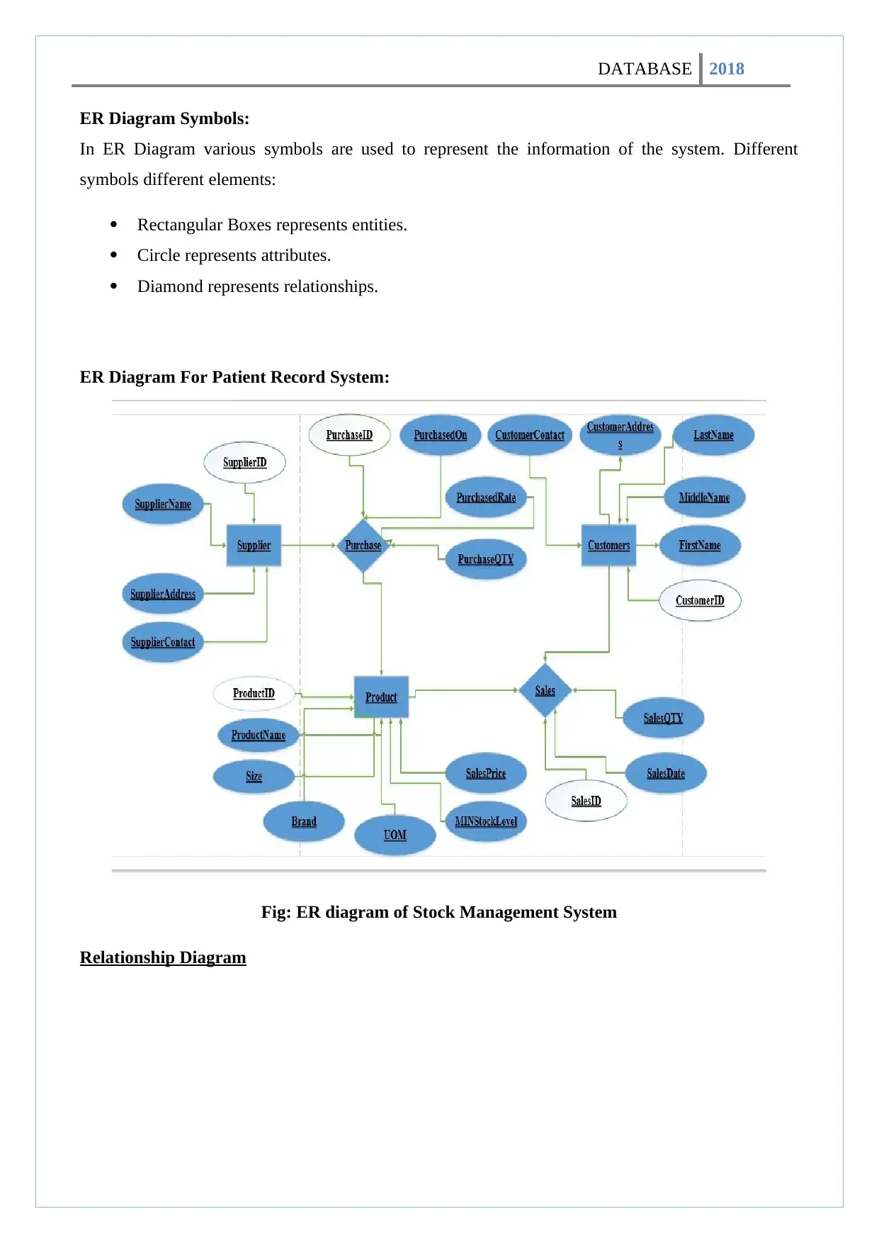
ER Diagram Symbols:
In ER Diagram various symbols are used to represent the information of the system. Different
symbols different elements:
Rectangular Boxes represents entities.
Circle represents attributes.
Diamond represents relationships.
ER Diagram For Patient Record System:
Fig: ER diagram of Stock Management System
Relationship Diagram
DATABASE 2018
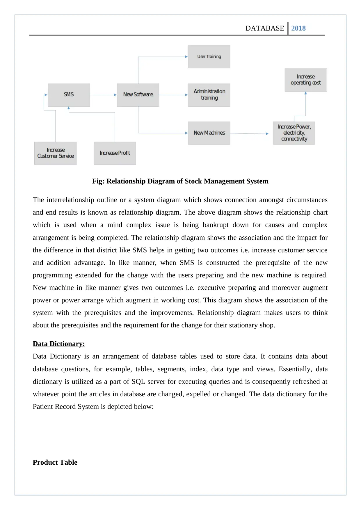
Fig: Relationship Diagram of Stock Management System
The interrelationship outline or a system diagram which shows connection amongst circumstances
and end results is known as relationship diagram. The above diagram shows the relationship chart
which is used when a mind complex issue is being bankrupt down for causes and complex
arrangement is being completed. The relationship diagram shows the association and the impact for
the difference in that district like SMS helps in getting two outcomes i.e. increase customer service
and addition advantage. In like manner, when SMS is constructed the prerequisite of the new
programming extended for the change with the users preparing and the new machine is required.
New machine in like manner gives two outcomes i.e. executive preparing and moreover augment
power or power arrange which augment in working cost. This diagram shows the association of the
system with the prerequisites and the improvements. Relationship diagram makes users to think
about the prerequisites and the requirement for the change for their stationary shop.
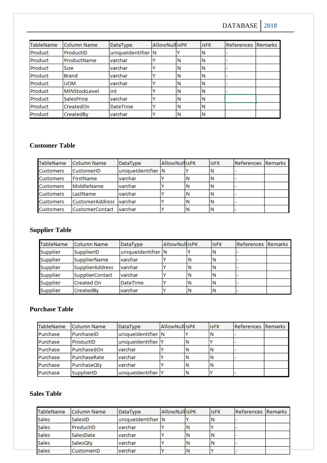
Data Dictionary:
Data Dictionary is an arrangement of database tables used to store data. It contains data about
database questions, for example, tables, segments, index, data type and views. Essentially, data
dictionary is utilized as a part of SQL server for executing queries and is consequently refreshed at
whatever point the articles in database are changed, expelled or changed. The data dictionary for the
Patient Record System is depicted below:
Product Table
Fig: Relationship Diagram of Stock Management System
The interrelationship outline or a system diagram which shows connection amongst circumstances
and end results is known as relationship diagram. The above diagram shows the relationship chart
which is used when a mind complex issue is being bankrupt down for causes and complex
arrangement is being completed. The relationship diagram shows the association and the impact for
the difference in that district like SMS helps in getting two outcomes i.e. increase customer service
and addition advantage. In like manner, when SMS is constructed the prerequisite of the new
programming extended for the change with the users preparing and the new machine is required.
New machine in like manner gives two outcomes i.e. executive preparing and moreover augment
power or power arrange which augment in working cost. This diagram shows the association of the
system with the prerequisites and the improvements. Relationship diagram makes users to think
about the prerequisites and the requirement for the change for their stationary shop.
Data Dictionary:
Data Dictionary is an arrangement of database tables used to store data. It contains data about
database questions, for example, tables, segments, index, data type and views. Essentially, data
dictionary is utilized as a part of SQL server for executing queries and is consequently refreshed at
whatever point the articles in database are changed, expelled or changed. The data dictionary for the
Patient Record System is depicted below:
Product Table
⊘ This is a preview!⊘
Do you want full access?
Subscribe today to unlock all pages.
Trusted by 1+ million students worldwide
DATABASE 2018
Customer Table
Supplier Table
Purchase Table
Sales Table
Customer Table
Supplier Table
Purchase Table
Sales Table
Paraphrase This Document
Need a fresh take? Get an instant paraphrase of this document with our AI Paraphraser
DATABASE 2018
Conclusion:
thus, the design of relational database system of the patient record system was made utilizing
different above devices and strategies. ER diagram caused in greater stretch out to design the system
recognizing different entities and traits. The ER Diagram instrument and information lexicon
demonstrated very valuable in effective design of interactive and appealing database system
satisfying every one of the users and system prerequisites.
DATABASE 2018
Task4/P2
Develop the database system with evidence of user interface, output and data validations, and
querying across multiple tables.
Introduction:
Database Management System is a software which enables clients to make, recover, update, delete
and manage information in a database. Different DBMS programming like: My SQL and so on are
utilized for performing such activities on database.
In this task, I have indicated how I have actualized different information approvals and queries in My
SQL to design database and I am will explain the limitations like primary key, foreign key, unique
key, not null key. Furthermore, I will likewise explain about the user interface, output, data
validation and joins like inner join, left join, right join, outer join etc.
Data Validation
Data validation is a procedure that guarantees the conveyance of perfect and clear data to the
programs, applications and services utilizing it. It checks for the integrity and validity of data that is
being inputted to various programming and its parts. Data validation guarantees that the data
conforms to the prerequisites and quality benchmarks.Data validation is otherwise called input
validation.
Constraints
Primary Key
A primary key is an uncommon relational database table section (or mix of segments) assigned to
uniquely identify every table record. A primary key’s main features are:
It must contain a unique value for each row of data.
It can't contain invalid qualities.
A primary key is either a current table section or a segment that is particularly produced by the
database as indicated by a characterized grouping.
Foreign key:
Foreign key acts as cross reference between tables and uniquely identifies a row/record in another
table.
⊘ This is a preview!⊘
Do you want full access?
Subscribe today to unlock all pages.
Trusted by 1+ million students worldwide
1 out of 43
Related Documents


Your All-in-One AI-Powered Toolkit for Academic Success.
+13062052269
info@desklib.com
Available 24*7 on WhatsApp / Email
![[object Object]](/_next/static/media/star-bottom.7253800d.svg)
Unlock your academic potential
Copyright © 2020–2026 A2Z Services. All Rights Reserved. Developed and managed by ZUCOL.