U22011 Structural Integrity: Steam Header Life Assessment Report
VerifiedAdded on 2022/08/22
|14
|2201
|13
Report
AI Summary
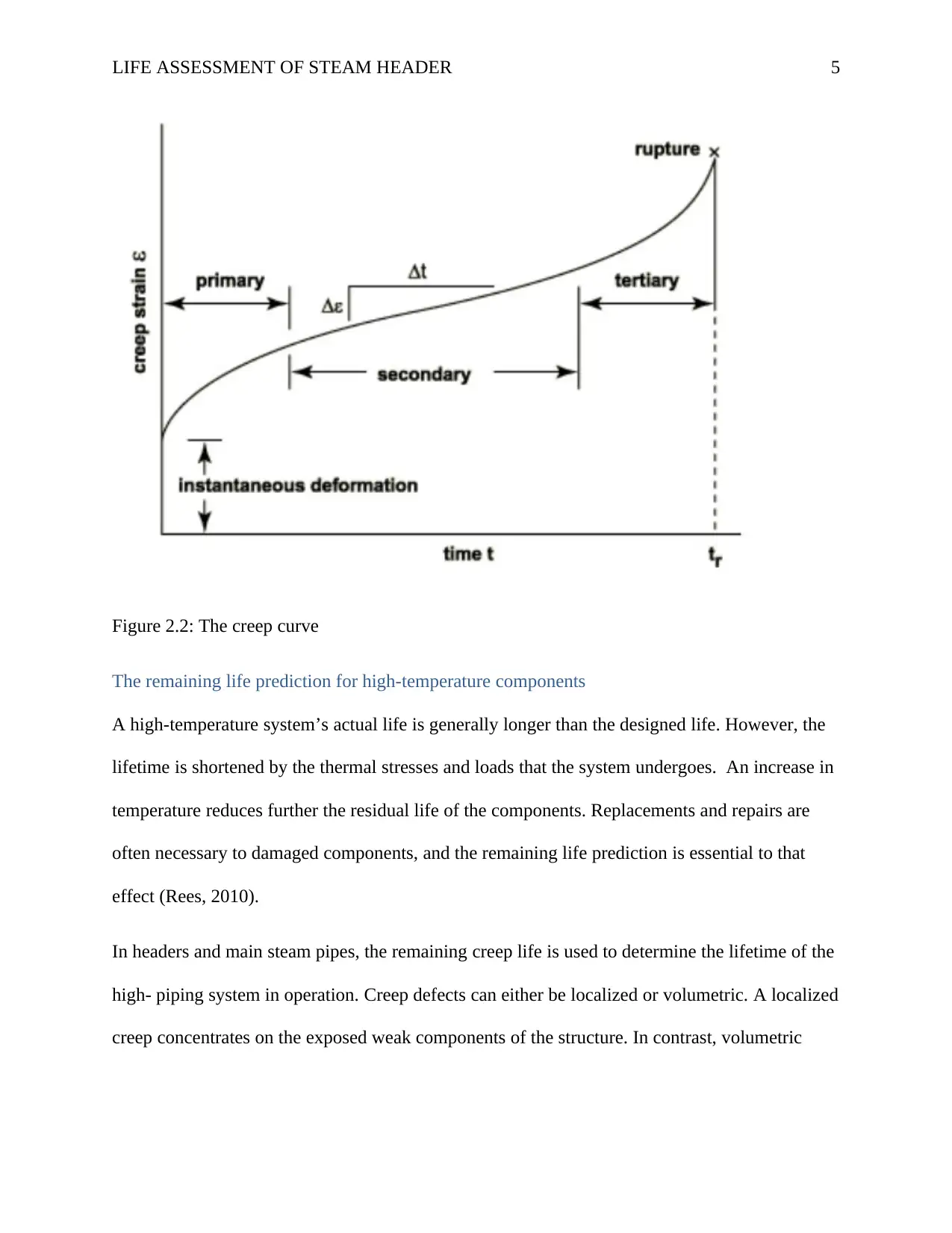
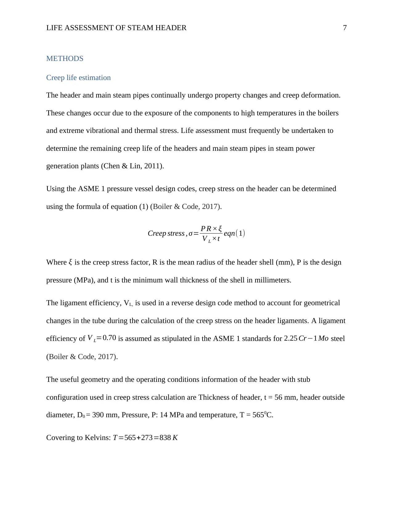
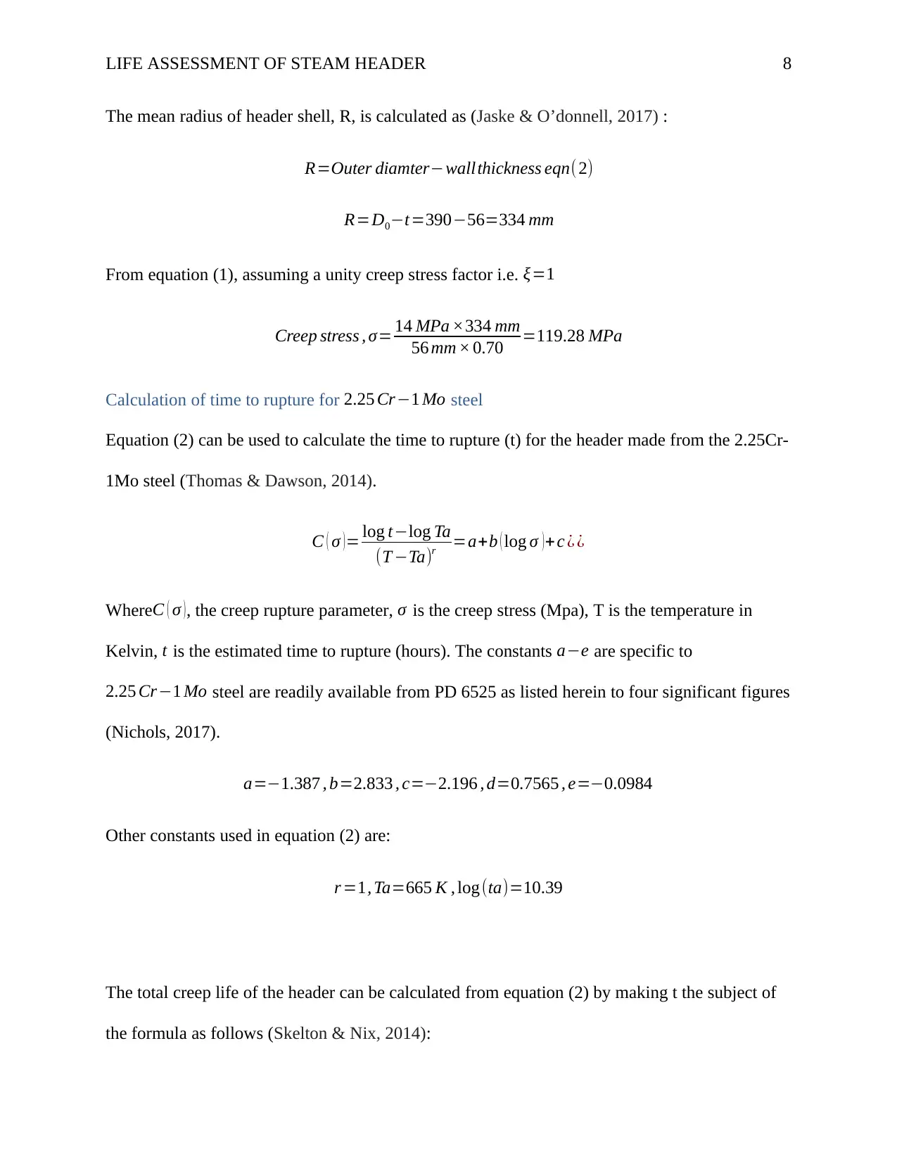
This report presents a life assessment of a super-heater header in a steam power plant, focusing on the challenges of high-temperature components. It begins with a literature review on creep, fatigue, and their impact on component failure, discussing creep damage, creep curves, and life prediction methodologies. The report then details the methodology using ASME pressure vessel design codes to estimate creep stress and calculate the time to rupture for 2.25Cr-1Mo steel. The analysis employs the Larson-Miller parameter approach to estimate the remaining creep life under different operational scenarios. The discussion highlights the importance of low alloy steels and the influence of geometrical changes on stress. The report concludes with recommendations for a more comprehensive life assessment, including creep analysis in conjunction with elastic stress analyses and the use of a whole piping system model. References to relevant literature are provided.

Running Head: LIFE ASSESSMENT OF STEAM HEADER
1
Part 2: Life Assessment of High-Temperature Header Piping and Tube System
Student Name
Institutional Affiliation
1
Part 2: Life Assessment of High-Temperature Header Piping and Tube System
Student Name
Institutional Affiliation
Paraphrase This Document
Need a fresh take? Get an instant paraphrase of this document with our AI Paraphraser

LIFE ASSESSMENT OF STEAM HEADER 2
Project II: STEAM HEADER LIFE ASSESSMENT
INTRODUCTION
Steam power generation plants are always associated with very high temperatures of about
5500C. High-temperature components are prone to failure due to fatigue, creep, thermal fatigue,
and creep-fatigue. Cracks are initiated and grow due to the creep and fatigue mechanisms, and
ultimate failure may eventually occur at any temperature. A key consideration in the selection for
steam power plant components is the fracture toughness of the material. Life assessment of the
components is necessary to predict the remaining life of the high-temperature components in
steam power plants for both safety and economic purposes (Kumar, Pandey & Das, 2014).
Low alloy steels are used extensively for high-temperature components such as steam pipes and
headers in power generation plants due to their excellent resistance to hydrogen attack and
oxidation together with good elevated temperature creep strength. The creep and fatigue
developed due to thermal stress are the main life-limiting factors of the steam pipes and header's
useful life. This paper presents the life assessment of a super-heater header using the ASME
pressure vessel design codes (Aronson et al., 2010).

LIFE ASSESSMENT OF STEAM HEADER 3
LITERATURE REVIEW
In steam power plants, the high-temperature components are prone to failure due to fatigue,
creep, thermal fatigue, and creep-fatigue. Cracks initiation and growth are due to the creep, and
fatigue mechanisms and ultimate failure may eventually occur at any temperature (Nicholas,
2017)
Creep Damage
Creep is the main high-temperature failure in main steam pipes and headers and can take several
forms. Dimensional changes as a result of creep deformation may cause loss of clearance,
distortions, and wall thinning in pipes and headers. When a material is continuously exposed to
high operating temperatures, brittle failure may occur due to crack growths at the welds and high
stressed crack regions. The available creep life prediction approaches for power plant
components can be classified broadly into post-service examination approach and operational
approach. Life prediction methodology is more appropriately based on essential creep
deformation data, such as the relationship between creep rate and stress (Miller & Priest, 2017.
The creep curve
The rate of creep increases with the increase in stress and temperature of the material as shown
in figure 2.1 (Kumar, Pandey & Das, 2014)
⊘ This is a preview!⊘
Do you want full access?
Subscribe today to unlock all pages.

Trusted by 1+ million students worldwide

LIFE ASSESSMENT OF STEAM HEADER 4
Figure 2.1: Creep rate as affected by temperature and stress.
The creep strain curve shown in figure 2.2 divides the creep process into three phases, with the
creep strain rate as the slope of the curve. The three distinct phases are the primary creep,
secondary creep, and the tertiary creep (Lukáš & Klesnil, 2011).
Paraphrase This Document
Need a fresh take? Get an instant paraphrase of this document with our AI Paraphraser

LIFE ASSESSMENT OF STEAM HEADER 5
Figure 2.2: The creep curve
The remaining life prediction for high-temperature components
A high-temperature system’s actual life is generally longer than the designed life. However, the
lifetime is shortened by the thermal stresses and loads that the system undergoes. An increase in
temperature reduces further the residual life of the components. Replacements and repairs are
often necessary to damaged components, and the remaining life prediction is essential to that
effect (Rees, 2010).
In headers and main steam pipes, the remaining creep life is used to determine the lifetime of the
high- piping system in operation. Creep defects can either be localized or volumetric. A localized
creep concentrates on the exposed weak components of the structure. In contrast, volumetric

LIFE ASSESSMENT OF STEAM HEADER 6
creep originates due to nominal stress are multiple small cracks spreading randomly over a large
structure area (Rao, 2019).
Use of creep-resistant steels.
Low alloy ferritic steels are used in steam power plants for high-temperature applications due to
their resistance to creep deformation. Molybdenum steels (Mo-steels) have increased creep-
rupture strength and reduced creep ductility. However, they cannot be applied at temperatures
above 5000C due to decomposition and graphitization. Mo-steels are alloyed with Chromium to
form CrMo-steels, which can withstand temperatures above 5000C (Boller & Seeger, 2013).
⊘ This is a preview!⊘
Do you want full access?
Subscribe today to unlock all pages.

Trusted by 1+ million students worldwide

LIFE ASSESSMENT OF STEAM HEADER 7
METHODS
Creep life estimation
The header and main steam pipes continually undergo property changes and creep deformation.
These changes occur due to the exposure of the components to high temperatures in the boilers
and extreme vibrational and thermal stress. Life assessment must frequently be undertaken to
determine the remaining creep life of the headers and main steam pipes in steam power
generation plants (Chen & Lin, 2011).
Using the ASME 1 pressure vessel design codes, creep stress on the header can be determined
using the formula of equation (1) (Boiler & Code, 2017).
Creep stress , σ= P R × ξ
V L ×t eqn(1)
Where ξ is the creep stress factor, R is the mean radius of the header shell (mm), P is the design
pressure (MPa), and t is the minimum wall thickness of the shell in millimeters.
The ligament efficiency, VL, is used in a reverse design code method to account for geometrical
changes in the tube during the calculation of the creep stress on the header ligaments. A ligament
efficiency of V L=0.70 is assumed as stipulated in the ASME 1 standards for 2.25 Cr−1 Mo steel
(Boiler & Code, 2017).
The useful geometry and the operating conditions information of the header with stub
configuration used in creep stress calculation are Thickness of header, t = 56 mm, header outside
diameter, D0 = 390 mm, Pressure, P: 14 MPa and temperature, T = 5650C.
Covering to Kelvins: T =565+273=838 K
Paraphrase This Document
Need a fresh take? Get an instant paraphrase of this document with our AI Paraphraser

LIFE ASSESSMENT OF STEAM HEADER 8
The mean radius of header shell, R, is calculated as (Jaske & O’donnell, 2017) :
R=Outer diamter−wallthickness eqn(2)
R=D0−t=390−56=334 mm
From equation (1), assuming a unity creep stress factor i.e. ξ=1
Creep stress , σ= 14 MPa ×334 mm
56 mm × 0.70 =119.28 MPa
Calculation of time to rupture for 2.25 Cr−1 Mo steel
Equation (2) can be used to calculate the time to rupture (t) for the header made from the 2.25Cr-
1Mo steel (Thomas & Dawson, 2014).
C ( σ ) = log t−log Ta
(T −Ta)r =a+b ( log σ ) + c ¿ ¿
WhereC ( σ ), the creep rupture parameter, σ is the creep stress (Mpa), T is the temperature in
Kelvin, t is the estimated time to rupture (hours). The constants a−e are specific to
2.25 Cr−1 Mo steel are readily available from PD 6525 as listed herein to four significant figures
(Nichols, 2017).
a=−1.387 , b=2.833 , c=−2.196 , d=0.7565 , e=−0.0984
Other constants used in equation (2) are:
r =1, Ta=665 K , log(ta)=10.39
The total creep life of the header can be calculated from equation (2) by making t the subject of
the formula as follows (Skelton & Nix, 2014):

LIFE ASSESSMENT OF STEAM HEADER 9
log t−log(ta)=(T −Ta)r ׿
log t=log(ta)+(T −Ta )r ׿
log t=10.39+¿
∴ log t=5.3392
Total creep life, t=105.3392=218,373 hours
The remaining creep life of the header is given by [6]:
trem=Total creep life−Operating time
trem=218,373−82000=136 , 373 hours
From the life assessment conducted, the estimated remaining life for the two-shift mode is
136,373 hours.
⊘ This is a preview!⊘
Do you want full access?
Subscribe today to unlock all pages.

Trusted by 1+ million students worldwide

LIFE ASSESSMENT OF STEAM HEADER 10
ANALYSIS
Different models for creeps have been developed to estimate the creep life of materials. Larson-
Miller parameter approach is used for applications where constant temperature operations are
maintained with time. The parameter can be used to estimate the time to rupture by data
extrapolation using the formula of equation (3) (Skelton, 2014).
PLM=T (log tr +C) eqn(3)
Where tr is the time to rupture, T is the temperature in degrees Rankine, and P is the Larsen-
Miller Parameter, which can be obtained from nominal stress versus P creep curves of the
2.25Cr-1Mo material used (Chopra & Shack, 2018).
The remaining creep life is calculated as: trem=tr −operating time(¿ hours)
The proposed two-shifting mode will lead to longer years of plant use, but the estimated
remaining creep life in hours will remain the same.
DISCUSSION
In steam power plant piping, low alloy steels have been used due to beneficial properties on
creep rupture. According to material specifications of the ASME B31.1 standards, CMV low
alloy steel pipe materials have been manufactured with the main alloying elements as Mo (0.5 wt
%), Cr (0.5%) and V(0.25 %) which improve the creep strength (Boiler & Code, 2017).
A geometrical change of the tubes will affect the stress in the header. The creep stress has an
inverse relationship with the minimum tube thickness, as shown in the following equation (1).
The fatigue and the creep life of the header are affected by tube dimensions such as thickness.
Paraphrase This Document
Need a fresh take? Get an instant paraphrase of this document with our AI Paraphraser

LIFE ASSESSMENT OF STEAM HEADER 11
Ligament efficiency included in equation (1) accounts for the changes in the geometry of the
tubes/stubs (Boller & Seeger, 2013).
Ligament efficiency included in equation (1) accounts for the changes in the geometry of the
tubes/stubs (Boller & Seeger, 2013).

LIFE ASSESSMENT OF STEAM HEADER 12
CONCLUSION
Using ASME 1 standards, creep life estimation was done based on the geometry and the
operating conditions of the header using the standard’s creep data for the 2.25Cr-1Mo material.
The creep stress was calculated from formulas and assumptions, as illustrated under the method.
From the life assessment conducted, the estimated remaining life for the two-shift mode was
obtained and analyzed. As a recommendation, creep analysis should be used in conjunction with
the elastic stress analyses to ensure a more elaborate life assessment of the components is done
based on many aspects. Lastly, a whole piping system model should be used instead of sections
to ensure correct creep analysis and recommend-ably, stress analysis in life assessment of high-
temperature components.
⊘ This is a preview!⊘
Do you want full access?
Subscribe today to unlock all pages.

Trusted by 1+ million students worldwide
1 out of 14
Related Documents

Your All-in-One AI-Powered Toolkit for Academic Success.
+13062052269
info@desklib.com
Available 24*7 on WhatsApp / Email
Unlock your academic potential
Copyright © 2020–2025 A2Z Services. All Rights Reserved. Developed and managed by ZUCOL.