Design and Analysis of Steel Beams: Calculations and Failures
VerifiedAdded on 2022/09/28
|10
|842
|36
Report
AI Summary
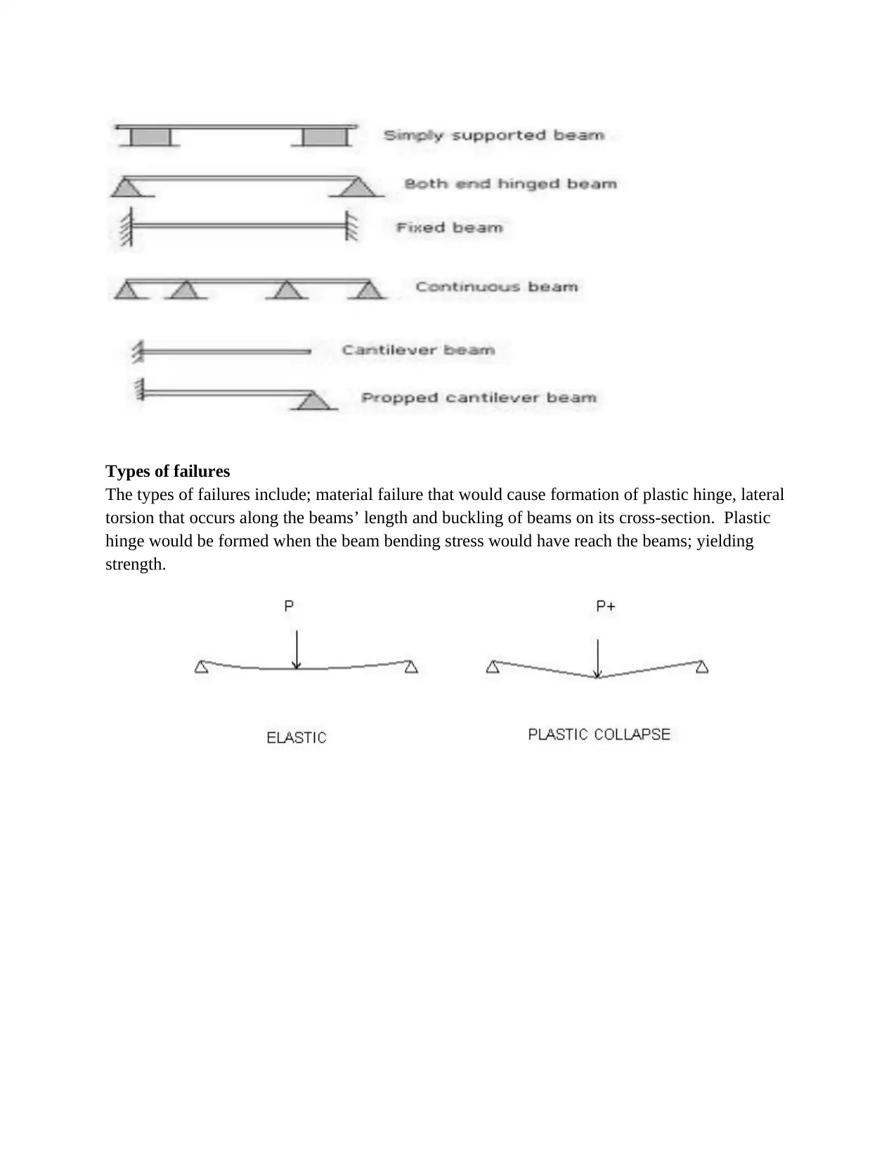
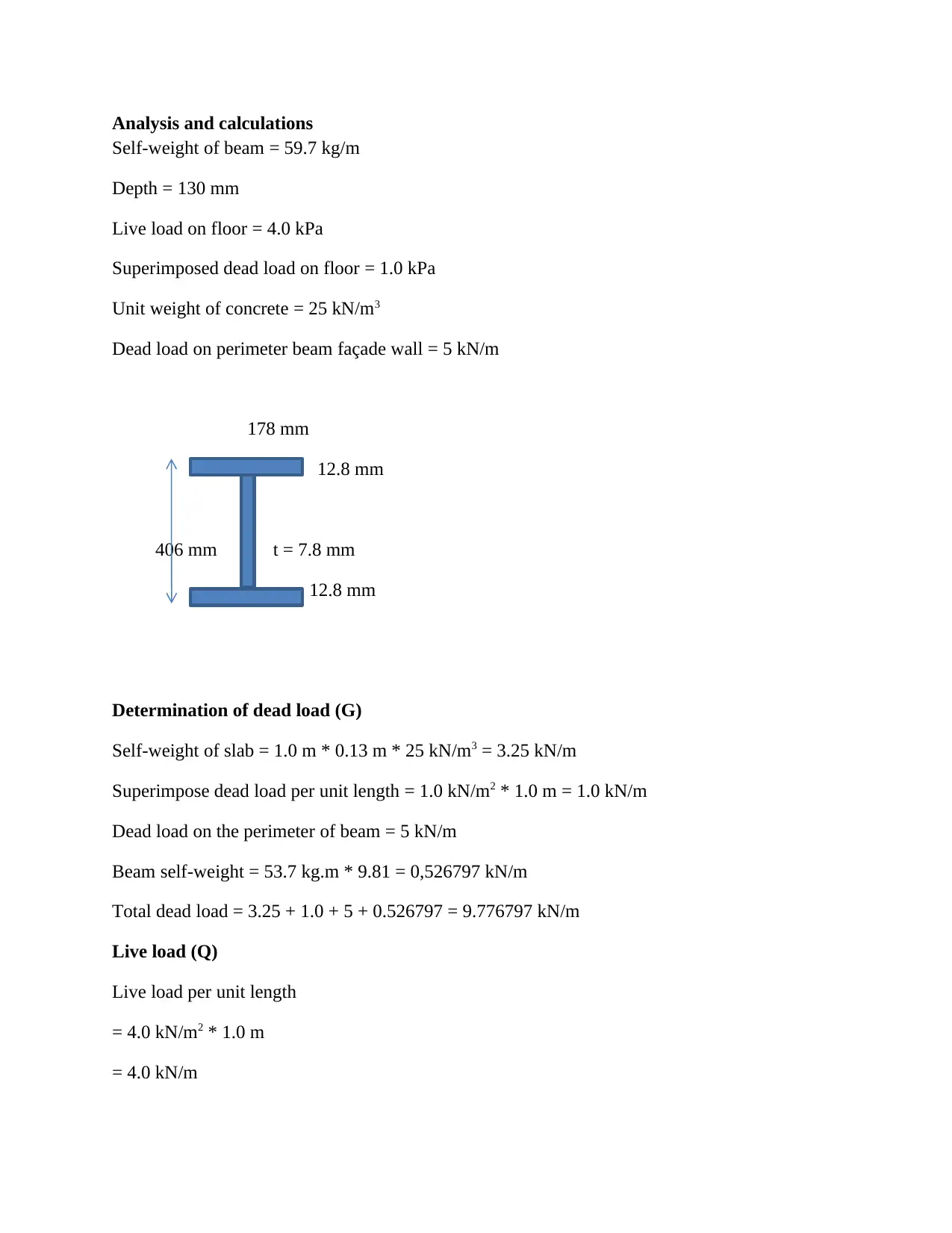
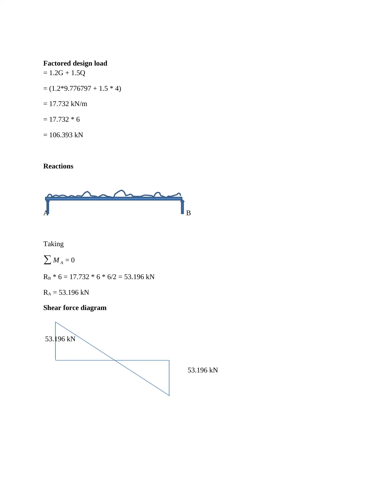
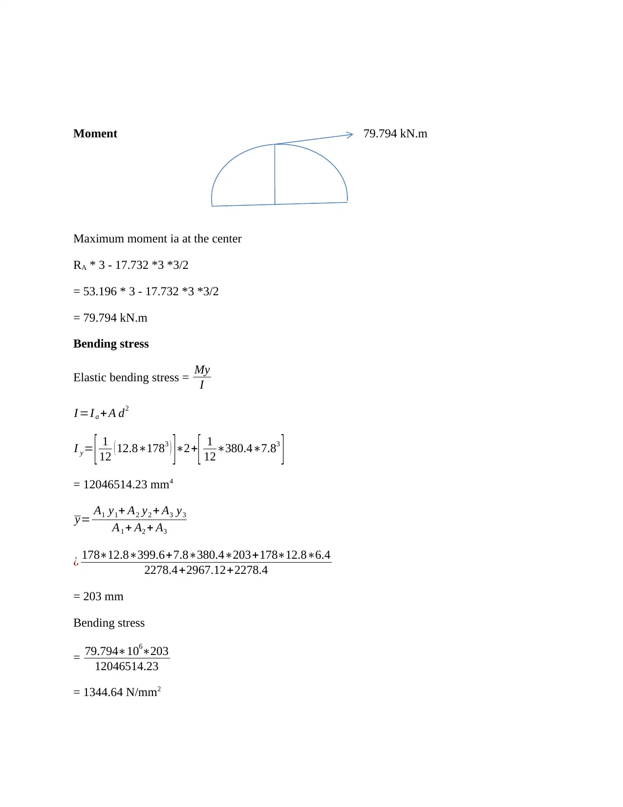
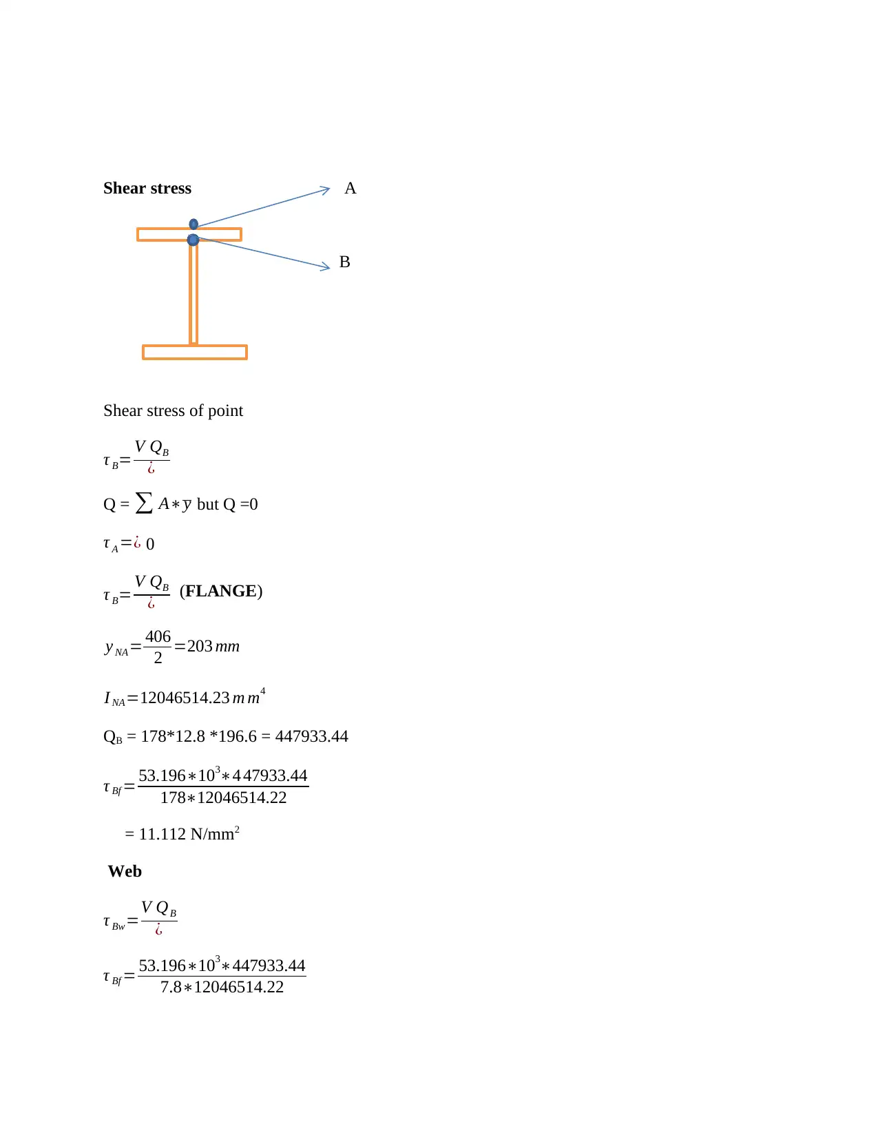
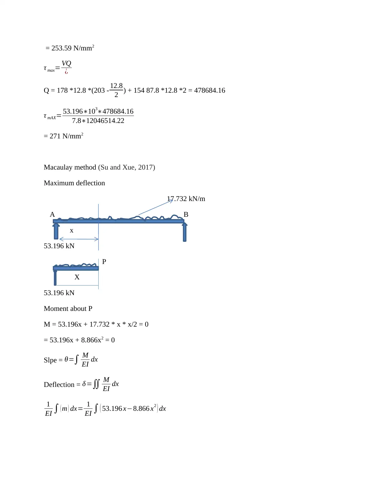
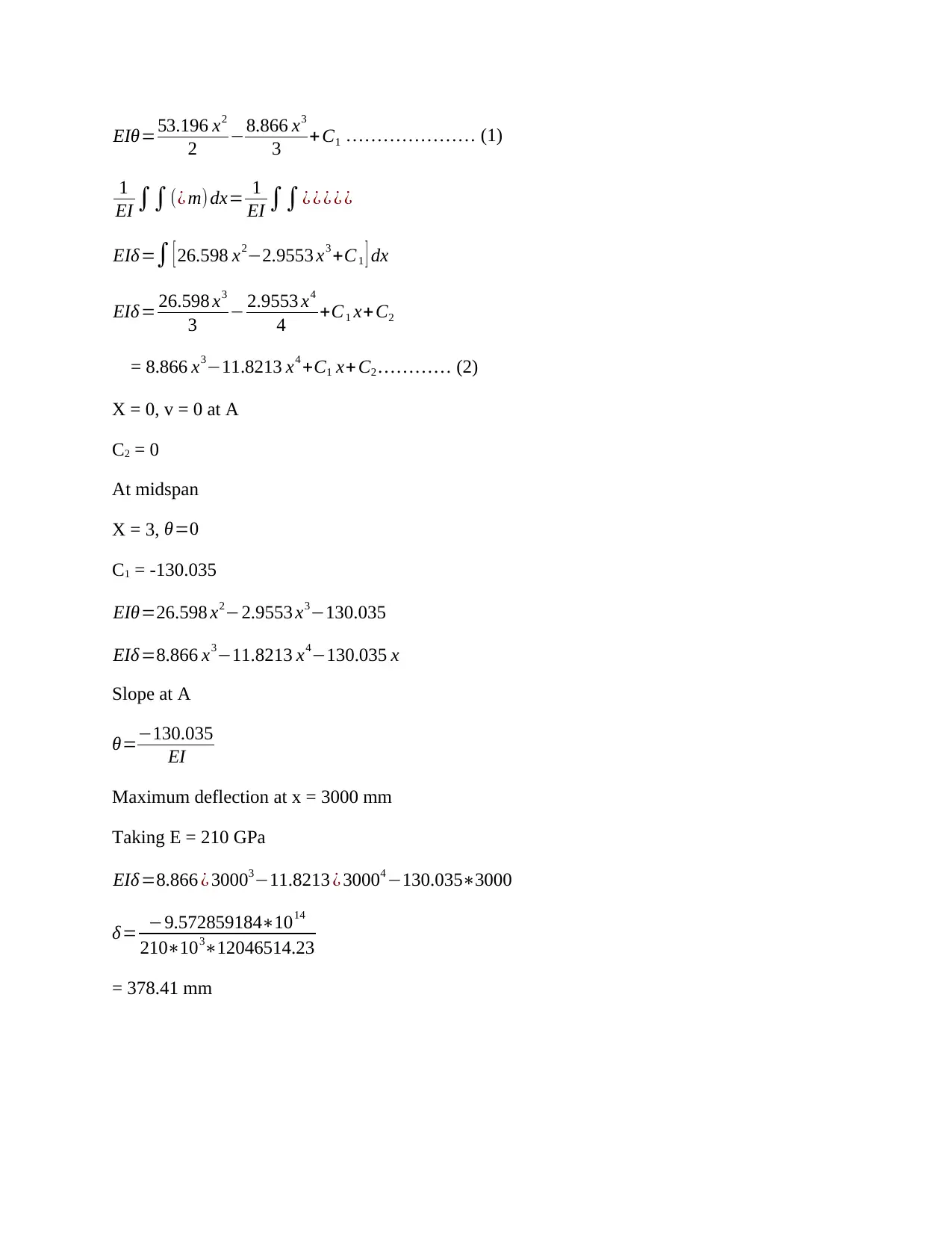
This report focuses on the design and analysis of steel beams, a critical structural element. It begins with an introduction to beams, their structural features like moment of inertia and stresses, and classifies different types of beams such as fixed, simply supported, and cantilever beams. The report al...
Read More
Contribute Materials
Your contribution can guide someone’s learning journey. Share your
documents today.

DESIGN OF STEEL BEAMS
Contents
Introduction.................................................................................................................................................2
Structural features....................................................................................................................................2
Types of beams........................................................................................................................................2
Types of failures......................................................................................................................................3
Analysis and calculations............................................................................................................................4
Factored design load............................................................................................................................5
Conclusion...................................................................................................................................................9
References.................................................................................................................................................10
Secure Best Marks with AI Grader
Need help grading? Try our AI Grader for instant feedback on your assignments.

Introduction
Beams are structural elements that would withstand load by resisting bending. The bending force
from beam own weight and external loadings would be exerted into the beam, the external loads’
reactions would result to bending moment.
Structural features
Moment of inertia
Moment of inertia at a given axis would describe the difficulty an object would face while
changing its angular motion. It includes both the object mass and its distance from the axis
(Bischoff and Gross, 2010).
Beams stresses
The beams would experience tensile, compressive and shear stresses that would be
exerted by the applied loads (Belletti and Gasperi, 2010).
Types of beams
Beams are classified as;
1. Fixed beams – beams restrained from rotating though they have been beam supported on
both ends
2. Simply supported beams – beams that are allowed freely to rotate and are supported on
its end and no resistance moment would be experience
3. Overhanging beam – beams that extends beyond one of its end support
4. Continuous beam – extension of beams over two supports
5. Cantilever beams – beams projected and are fixed on one end
6. Trusses beam – beams that are strengthened by addition of cable from a truss

Types of failures
The types of failures include; material failure that would cause formation of plastic hinge, lateral
torsion that occurs along the beams’ length and buckling of beams on its cross-section. Plastic
hinge would be formed when the beam bending stress would have reach the beams; yielding
strength.
The types of failures include; material failure that would cause formation of plastic hinge, lateral
torsion that occurs along the beams’ length and buckling of beams on its cross-section. Plastic
hinge would be formed when the beam bending stress would have reach the beams; yielding
strength.

Analysis and calculations
Self-weight of beam = 59.7 kg/m
Depth = 130 mm
Live load on floor = 4.0 kPa
Superimposed dead load on floor = 1.0 kPa
Unit weight of concrete = 25 kN/m3
Dead load on perimeter beam façade wall = 5 kN/m
178 mm
12.8 mm
406 mm t = 7.8 mm
12.8 mm
Determination of dead load (G)
Self-weight of slab = 1.0 m * 0.13 m * 25 kN/m3 = 3.25 kN/m
Superimpose dead load per unit length = 1.0 kN/m2 * 1.0 m = 1.0 kN/m
Dead load on the perimeter of beam = 5 kN/m
Beam self-weight = 53.7 kg.m * 9.81 = 0,526797 kN/m
Total dead load = 3.25 + 1.0 + 5 + 0.526797 = 9.776797 kN/m
Live load (Q)
Live load per unit length
= 4.0 kN/m2 * 1.0 m
= 4.0 kN/m
Secure Best Marks with AI Grader
Need help grading? Try our AI Grader for instant feedback on your assignments.

Factored design load
= 1.2G + 1.5Q
= (1.2*9.776797 + 1.5 * 4)
= 17.732 kN/m
= 17.732 * 6
= 106.393 kN
Reactions
A B
Taking
∑ M A = 0
RB * 6 = 17.732 * 6 * 6/2 = 53.196 kN
RA = 53.196 kN
Shear force diagram
53.196 kN
53.196 kN
= 1.2G + 1.5Q
= (1.2*9.776797 + 1.5 * 4)
= 17.732 kN/m
= 17.732 * 6
= 106.393 kN
Reactions
A B
Taking
∑ M A = 0
RB * 6 = 17.732 * 6 * 6/2 = 53.196 kN
RA = 53.196 kN
Shear force diagram
53.196 kN
53.196 kN

Moment 79.794 kN.m
Maximum moment ia at the center
RA * 3 - 17.732 *3 *3/2
= 53.196 * 3 - 17.732 *3 *3/2
= 79.794 kN.m
Bending stress
Elastic bending stress = My
I
I =I a + A d2
I y= [ 1
12 ( 12.8∗1783 ) ]∗2+
[ 1
12∗380.4∗7.83
]
= 12046514.23 mm4
y= A1 y1+ A2 y2 + A3 y3
A1 + A2 + A3
¿ 178∗12.8∗399.6+7.8∗380.4∗203+178∗12.8∗6.4
2278.4+2967.12+2278.4
= 203 mm
Bending stress
= 79.794∗106∗203
12046514.23
= 1344.64 N/mm2

Shear stress A
B
Shear stress of point
τ B= V QB
¿
Q = ∑ A∗y but Q =0
τ A =¿ 0
τ B= V QB
¿ (FLANGE)
y NA= 406
2 =203 mm
I NA=12046514.23 m m4
QB = 178*12.8 *196.6 = 447933.44
τ Bf = 53.196∗103∗4 47933.44
178∗12046514.22
= 11.112 N/mm2
Web
τ Bw=V QB
¿
τ Bf = 53.196∗103∗447933.44
7.8∗12046514.22
B
Shear stress of point
τ B= V QB
¿
Q = ∑ A∗y but Q =0
τ A =¿ 0
τ B= V QB
¿ (FLANGE)
y NA= 406
2 =203 mm
I NA=12046514.23 m m4
QB = 178*12.8 *196.6 = 447933.44
τ Bf = 53.196∗103∗4 47933.44
178∗12046514.22
= 11.112 N/mm2
Web
τ Bw=V QB
¿
τ Bf = 53.196∗103∗447933.44
7.8∗12046514.22
Paraphrase This Document
Need a fresh take? Get an instant paraphrase of this document with our AI Paraphraser

= 253.59 N/mm2
τ max= VQ
¿
Q = 178 *12.8 *(203 - 12.8
2 ) + 154 87.8 *12.8 *2 = 478684.16
τ mAX= 53.196∗103∗478684.16
7.8∗12046514.22
= 271 N/mm2
Macaulay method (Su and Xue, 2017)
Maximum deflection
17.732 kN/m
A B
x
53.196 kN
P
X
53.196 kN
Moment about P
M = 53.196x + 17.732 * x * x/2 = 0
= 53.196x + 8.866x2 = 0
Slpe = θ=∫ M
EI dx
Deflection = δ =∬ M
EI dx
1
EI ∫ ( m ) dx= 1
EI ∫ ( 53.196 x−8.866 x2 ) dx

EIθ=53.196 x2
2 −8.866 x3
3 + C1 ………………… (1)
1
EI ∫∫(¿ m) dx= 1
EI ∫∫¿ ¿ ¿ ¿ ¿
EIδ=∫ [ 26.598 x2−2.9553 x3 +C1 ] dx
EIδ = 26.598 x3
3 − 2.9553 x4
4 +C1 x+ C2
= 8.866 x3−11.8213 x4 +C1 x+ C2………… (2)
X = 0, v = 0 at A
C2 = 0
At midspan
X = 3, θ=0
C1 = -130.035
EIθ=26.598 x2−2.9553 x3−130.035
EIδ =8.866 x3−11.8213 x4−130.035 x
Slope at A
θ=−130.035
EI
Maximum deflection at x = 3000 mm
Taking E = 210 GPa
EIδ =8.866 ¿ 30003−11.8213 ¿ 30004 −130.035∗3000
δ= −9.572859184∗1014
210∗103∗12046514.23
= 378.41 mm

Conclusion
From the calculation we determined the reaction at the ends of the beam was 53.196 kN, the
maximum moment calculated was 79.794 kN.m. The maximum shear stress was 271 N/mm2.
The deflection calculated was 378.41 mm
References
Bischoff, P.H. and Gross, S.P., 2010. Equivalent moment of inertia based on integration of
curvature. Journal of Composites for Construction, 15(3), pp.263-273.
Belletti, B. and Gasperi, A., 2010. Behavior of prestressed steel beams. Journal of structural
engineering, 136(9), pp.1131-1139.
Su, Z. and Xue, Y., 2017, June. A Novel Method of Equivalent Replacement Beams for
Displacement Computation of Euler-Bernoulli beams. In 2017 6th International Conference on
Energy and Environmental Protection (ICEEP 2017). Atlantis Press.
1 out of 10

Your All-in-One AI-Powered Toolkit for Academic Success.
+13062052269
info@desklib.com
Available 24*7 on WhatsApp / Email
Unlock your academic potential
© 2024 | Zucol Services PVT LTD | All rights reserved.