An Analysis of Stepper Motors: Principles, Types, and Control Methods
VerifiedAdded on 2022/05/02
|14
|2234
|53
Report
AI Summary
This report provides a comprehensive overview of stepper motors, beginning with an introduction to their operational principles and applications. It delves into the three primary types of stepper motors: permanent magnet, variable reluctance, and hybrid, detailing their construction and operational characteristics. The report further examines key parameters such as step angle, resolution, and stepping frequency, which are crucial for understanding motor performance. It then explores various stepper drive techniques, including full step, half step, micro-stepping, and wave drive modes, as well as the distinctions between unipolar and bipolar drives. The document concludes with a discussion on snubbing techniques used to mitigate issues in stepper motor circuits. This report is a valuable resource for students and professionals seeking to understand the intricacies of stepper motor technology.
Assignment – August 2021
STEPPER MOTORS
STEPPER MOTORS
Paraphrase This Document
Need a fresh take? Get an instant paraphrase of this document with our AI Paraphraser
Table of Contents
1. Introduction.........................................................................................................................................3
2. Principle of Operation..........................................................................................................................3
3. Types of Stepper Motors.....................................................................................................................3
1. Permanent Magnet Stepper Motor.................................................................................................4
2. Variable Reluctance Stepper motor.................................................................................................5
3. Hybrid Stepper Motor......................................................................................................................7
3.Step angle, Resolution and Stepping Frequency.......................................................................................8
1. Step Angle............................................................................................................................................8
2. Resolution............................................................................................................................................8
3. Stepping frequency..............................................................................................................................8
4. Stepper drive techniques.....................................................................................................................9
1.Full Step Mode (Two Phases ON).......................................................................................................9
2.Half Step Mode...................................................................................................................................10
3.Micro-stepping Mode.........................................................................................................................11
4.wave Drive Mode................................................................................................................................11
5.Unipolar and Bipolar Drives....................................................................................................................11
1.Unipolar Motor Drives........................................................................................................................12
2. Bipolar Motor Drives.........................................................................................................................12
6.Snubbing for stepper motors..................................................................................................................13
7. References.............................................................................................................................................14
Table of Figures
Fig 1: Example of a Permanent Magnet Stepper Motor
Fig 2: Permanent Magnet Stepping Motor
Fig 3: Clockwise Rotation of a Permanent Magnet Stepper motor
Fig 4: Variable Reluctance Stepper motor
Fig 4: Variable Reluctance Stepper motor
1. Introduction
Stepper motor, which converts electrical energy into mechanical energy, is a brushless synchronous
electrical motor. In stepper motor, attraction and repulsion between energized stator electromagnets
(using electrical supply) and rotor occurs rotating the motor shaft in specific angles.
For the operation of stepper motor no feedback is taken from motor shaft, thus making it suitable for
open loop position control. This motor being brushless cause it less maintaining with minimum
frictional losses.
2. Principle of Operation
The Stepper Motor consists of a stationary part called as stator whose windings are given an electrical
supply to magnetize it. The other part is the rotor with the spinning shaft. Rotor is either made of
permanent magnet or plain iron (Fe).
Electrical pulses generated in the controller are given as commands to the motor, rotating the rotor
shaft in specific angles known as step angles. The step angles are changed by changing the energizing
pattern while pulse frequency decide the motor speed.
Poles in the stepper motor enables it to position it precisely considering the input electrical pulses
without using feedback of the position of the output shaft (Open Loop Control). This is a main
advantage of stepper motor.
⊘ This is a preview!⊘
Do you want full access?
Subscribe today to unlock all pages.
Trusted by 1+ million students worldwide
In any stepper motor, the principle of operation can be simplified as the attraction and repulsion
between the electro magnetized stator the rotor, resulting the motor shaft rotate.
3. Types of Stepper Motors
There are three types of Stepper Motors namely:
• Permanent Magnet Stepper Motor
• Variable Reluctance Stepper Motor
• Hybrid stepper Motor
1. Permanent Magnet Stepper Motor
The operating principle of Permanent Magnet Stepper Motor is the attraction and repulsion between
the rotor permanent magnet and the stator electromagnets. The permanent-magnet rotor consists of
two or more poles, and it interacts with the electromagnetic field produced by the stator winding.
In the permanent magnet stepper motor, the stator windings are wound in the stator teeth, where
opposite pairs wound in series making one stator tooth as N- pole and its opposite as S- pole after
electric supply (excitation). It then attracts the poles of the rotor permanent magnets. The energizing
sequence decide the rotation direction of the shaft.
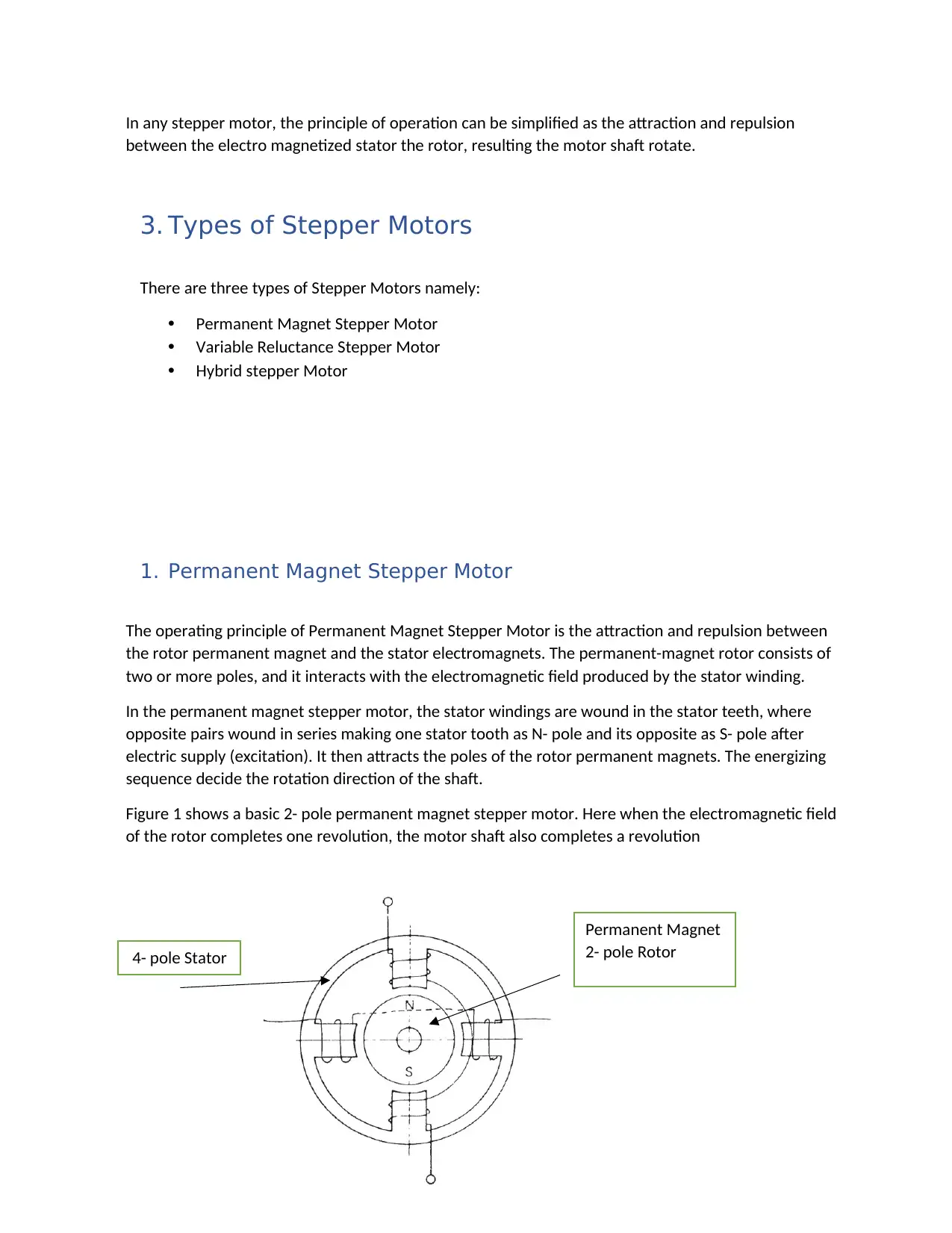
Figure 1 shows a basic 2- pole permanent magnet stepper motor. Here when the electromagnetic field
of the rotor completes one revolution, the motor shaft also completes a revolution
Permanent Magnet
2- pole Rotor4- pole Stator
between the electro magnetized stator the rotor, resulting the motor shaft rotate.
3. Types of Stepper Motors
There are three types of Stepper Motors namely:
• Permanent Magnet Stepper Motor
• Variable Reluctance Stepper Motor
• Hybrid stepper Motor
1. Permanent Magnet Stepper Motor
The operating principle of Permanent Magnet Stepper Motor is the attraction and repulsion between
the rotor permanent magnet and the stator electromagnets. The permanent-magnet rotor consists of
two or more poles, and it interacts with the electromagnetic field produced by the stator winding.
In the permanent magnet stepper motor, the stator windings are wound in the stator teeth, where
opposite pairs wound in series making one stator tooth as N- pole and its opposite as S- pole after
electric supply (excitation). It then attracts the poles of the rotor permanent magnets. The energizing
sequence decide the rotation direction of the shaft.
Figure 1 shows a basic 2- pole permanent magnet stepper motor. Here when the electromagnetic field
of the rotor completes one revolution, the motor shaft also completes a revolution
Permanent Magnet
2- pole Rotor4- pole Stator
Paraphrase This Document
Need a fresh take? Get an instant paraphrase of this document with our AI Paraphraser
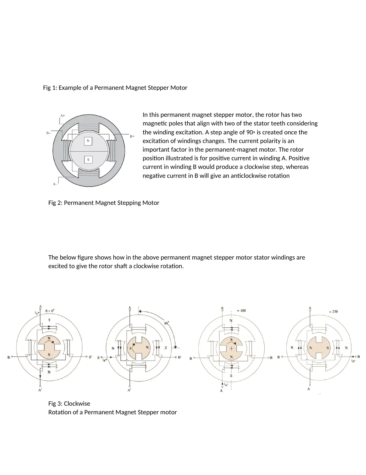
Fig 1: Example of a Permanent Magnet Stepper Motor
In this permanent magnet stepper motor, the rotor has two
magnetic poles that align with two of the stator teeth considering
the winding excitation. A step angle of 90◦ is created once the
excitation of windings changes. The current polarity is an
important factor in the permanent-magnet motor. The rotor
position illustrated is for positive current in winding A. Positive
current in winding B would produce a clockwise step, whereas
negative current in B will give an anticlockwise rotation
Fig 2: Permanent Magnet Stepping Motor
The below figure shows how in the above permanent magnet stepper motor stator windings are
excited to give the rotor shaft a clockwise rotation.
Fig 3: Clockwise
Rotation of a Permanent Magnet Stepper motor
2. Variable Reluctance Stepper motor
Fig 4: Variable Reluctance Stepper motor
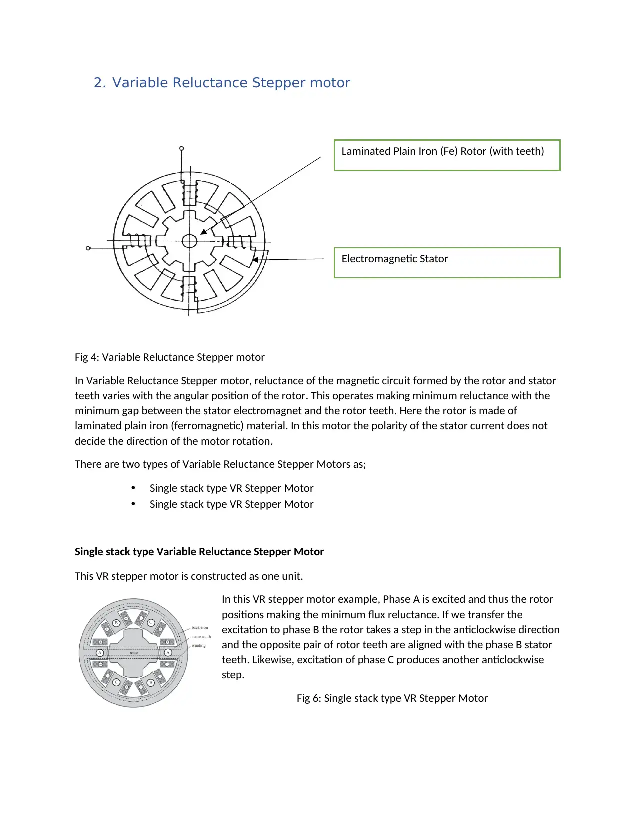
In Variable Reluctance Stepper motor, reluctance of the magnetic circuit formed by the rotor and stator
teeth varies with the angular position of the rotor. This operates making minimum reluctance with the
minimum gap between the stator electromagnet and the rotor teeth. Here the rotor is made of
laminated plain iron (ferromagnetic) material. In this motor the polarity of the stator current does not
decide the direction of the motor rotation.
There are two types of Variable Reluctance Stepper Motors as;
• Single stack type VR Stepper Motor
• Single stack type VR Stepper Motor
Single stack type Variable Reluctance Stepper Motor
This VR stepper motor is constructed as one unit.
In this VR stepper motor example, Phase A is excited and thus the rotor
positions making the minimum flux reluctance. If we transfer the
excitation to phase B the rotor takes a step in the anticlockwise direction
and the opposite pair of rotor teeth are aligned with the phase B stator
teeth. Likewise, excitation of phase C produces another anticlockwise
step.
Fig 6: Single stack type VR Stepper Motor
Laminated Plain Iron (Fe) Rotor (with teeth)
Electromagnetic Stator
Fig 4: Variable Reluctance Stepper motor
In Variable Reluctance Stepper motor, reluctance of the magnetic circuit formed by the rotor and stator
teeth varies with the angular position of the rotor. This operates making minimum reluctance with the
minimum gap between the stator electromagnet and the rotor teeth. Here the rotor is made of
laminated plain iron (ferromagnetic) material. In this motor the polarity of the stator current does not
decide the direction of the motor rotation.
There are two types of Variable Reluctance Stepper Motors as;
• Single stack type VR Stepper Motor
• Single stack type VR Stepper Motor
Single stack type Variable Reluctance Stepper Motor
This VR stepper motor is constructed as one unit.
In this VR stepper motor example, Phase A is excited and thus the rotor
positions making the minimum flux reluctance. If we transfer the
excitation to phase B the rotor takes a step in the anticlockwise direction
and the opposite pair of rotor teeth are aligned with the phase B stator
teeth. Likewise, excitation of phase C produces another anticlockwise
step.
Fig 6: Single stack type VR Stepper Motor
Laminated Plain Iron (Fe) Rotor (with teeth)
Electromagnetic Stator
⊘ This is a preview!⊘
Do you want full access?
Subscribe today to unlock all pages.
Trusted by 1+ million students worldwide
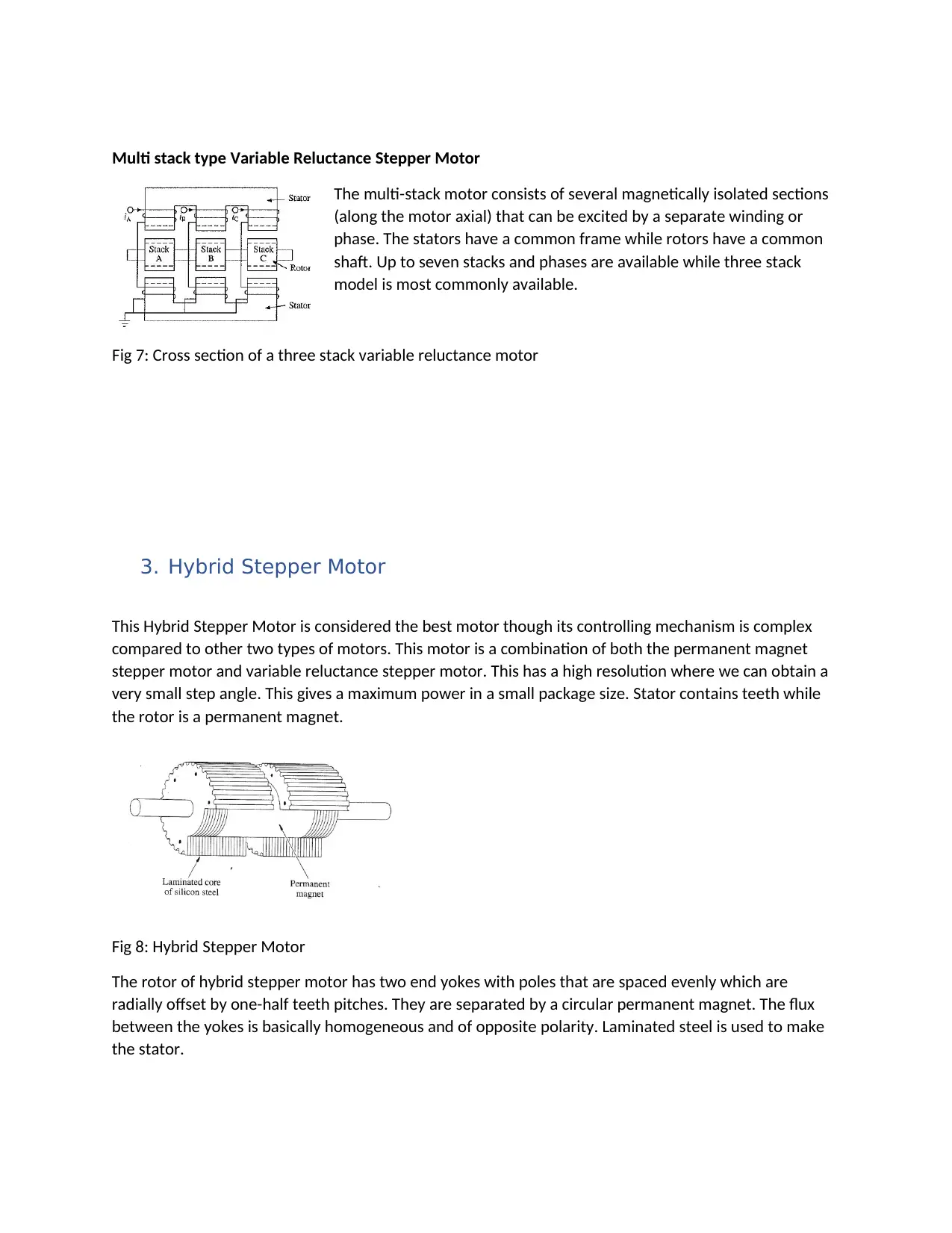
Multi stack type Variable Reluctance Stepper Motor
The multi-stack motor consists of several magnetically isolated sections
(along the motor axial) that can be excited by a separate winding or
phase. The stators have a common frame while rotors have a common
shaft. Up to seven stacks and phases are available while three stack
model is most commonly available.
Fig 7: Cross section of a three stack variable reluctance motor
3. Hybrid Stepper Motor
This Hybrid Stepper Motor is considered the best motor though its controlling mechanism is complex
compared to other two types of motors. This motor is a combination of both the permanent magnet
stepper motor and variable reluctance stepper motor. This has a high resolution where we can obtain a
very small step angle. This gives a maximum power in a small package size. Stator contains teeth while
the rotor is a permanent magnet.
Fig 8: Hybrid Stepper Motor
The rotor of hybrid stepper motor has two end yokes with poles that are spaced evenly which are
radially offset by one-half teeth pitches. They are separated by a circular permanent magnet. The flux
between the yokes is basically homogeneous and of opposite polarity. Laminated steel is used to make
the stator.
Paraphrase This Document
Need a fresh take? Get an instant paraphrase of this document with our AI Paraphraser
3.Step angle, Resolution and Stepping Frequency.
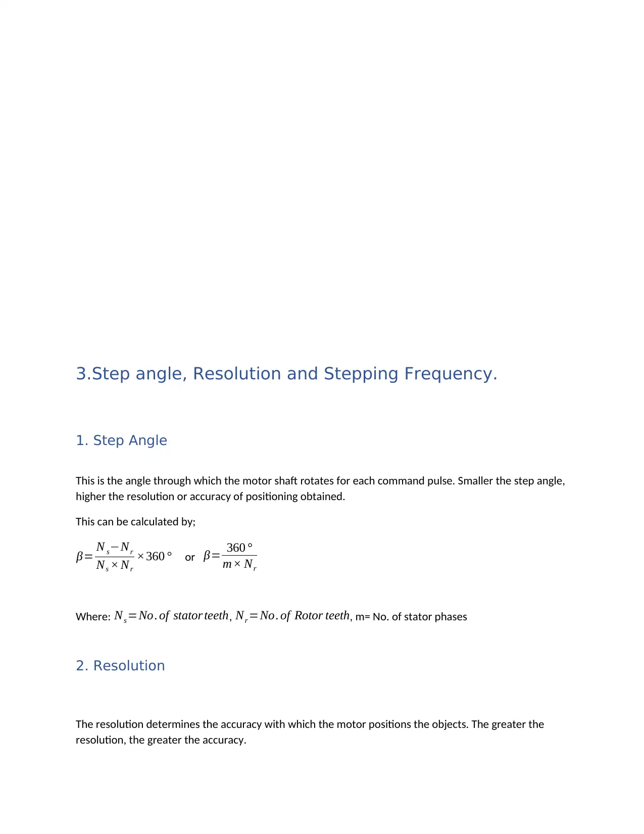
1. Step Angle
This is the angle through which the motor shaft rotates for each command pulse. Smaller the step angle,
higher the resolution or accuracy of positioning obtained.
This can be calculated by;
β= N s−Nr
Ns × Nr
×360 ° or β= 360 °
m× Nr
Where: Ns =No. of stator teeth, Nr =No. of Rotor teeth, m= No. of stator phases
2. Resolution
The resolution determines the accuracy with which the motor positions the objects. The greater the
resolution, the greater the accuracy.
Resolution= No . of Steps
Revolution
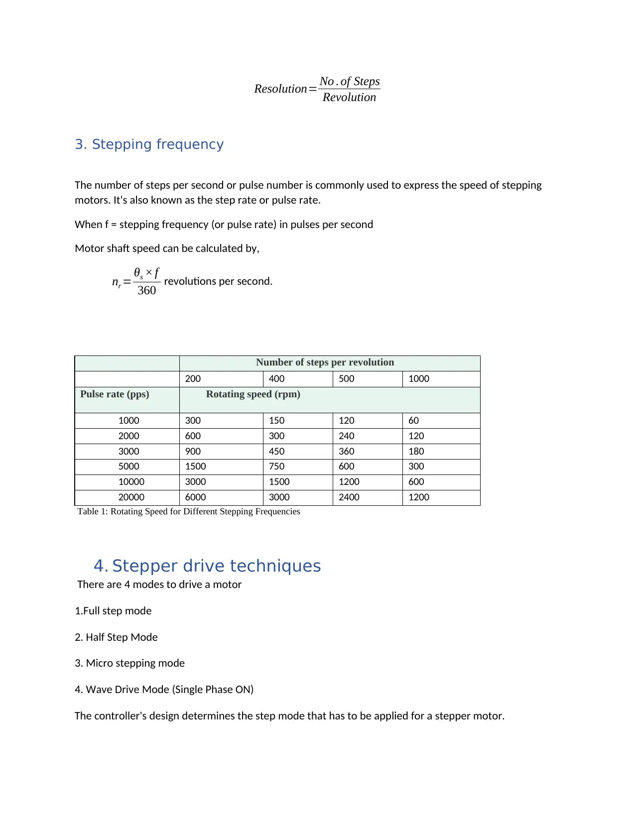
3. Stepping frequency
The number of steps per second or pulse number is commonly used to express the speed of stepping
motors. It's also known as the step rate or pulse rate.
When f = stepping frequency (or pulse rate) in pulses per second
Motor shaft speed can be calculated by,
nr = θs × f
360 revolutions per second.
Number of steps per revolution
200 400 500 1000
Pulse rate (pps) Rotating speed (rpm)
1000 300 150 120 60
2000 600 300 240 120
3000 900 450 360 180
5000 1500 750 600 300
10000 3000 1500 1200 600
20000 6000 3000 2400 1200
Table 1: Rotating Speed for Different Stepping Frequencies
4. Stepper drive techniques
There are 4 modes to drive a motor
1.Full step mode
2. Half Step Mode
3. Micro stepping mode
4. Wave Drive Mode (Single Phase ON)
The controller's design determines the step mode that has to be applied for a stepper motor.
Revolution
3. Stepping frequency
The number of steps per second or pulse number is commonly used to express the speed of stepping
motors. It's also known as the step rate or pulse rate.
When f = stepping frequency (or pulse rate) in pulses per second
Motor shaft speed can be calculated by,
nr = θs × f
360 revolutions per second.
Number of steps per revolution
200 400 500 1000
Pulse rate (pps) Rotating speed (rpm)
1000 300 150 120 60
2000 600 300 240 120
3000 900 450 360 180
5000 1500 750 600 300
10000 3000 1500 1200 600
20000 6000 3000 2400 1200
Table 1: Rotating Speed for Different Stepping Frequencies
4. Stepper drive techniques
There are 4 modes to drive a motor
1.Full step mode
2. Half Step Mode
3. Micro stepping mode
4. Wave Drive Mode (Single Phase ON)
The controller's design determines the step mode that has to be applied for a stepper motor.
⊘ This is a preview!⊘
Do you want full access?
Subscribe today to unlock all pages.
Trusted by 1+ million students worldwide
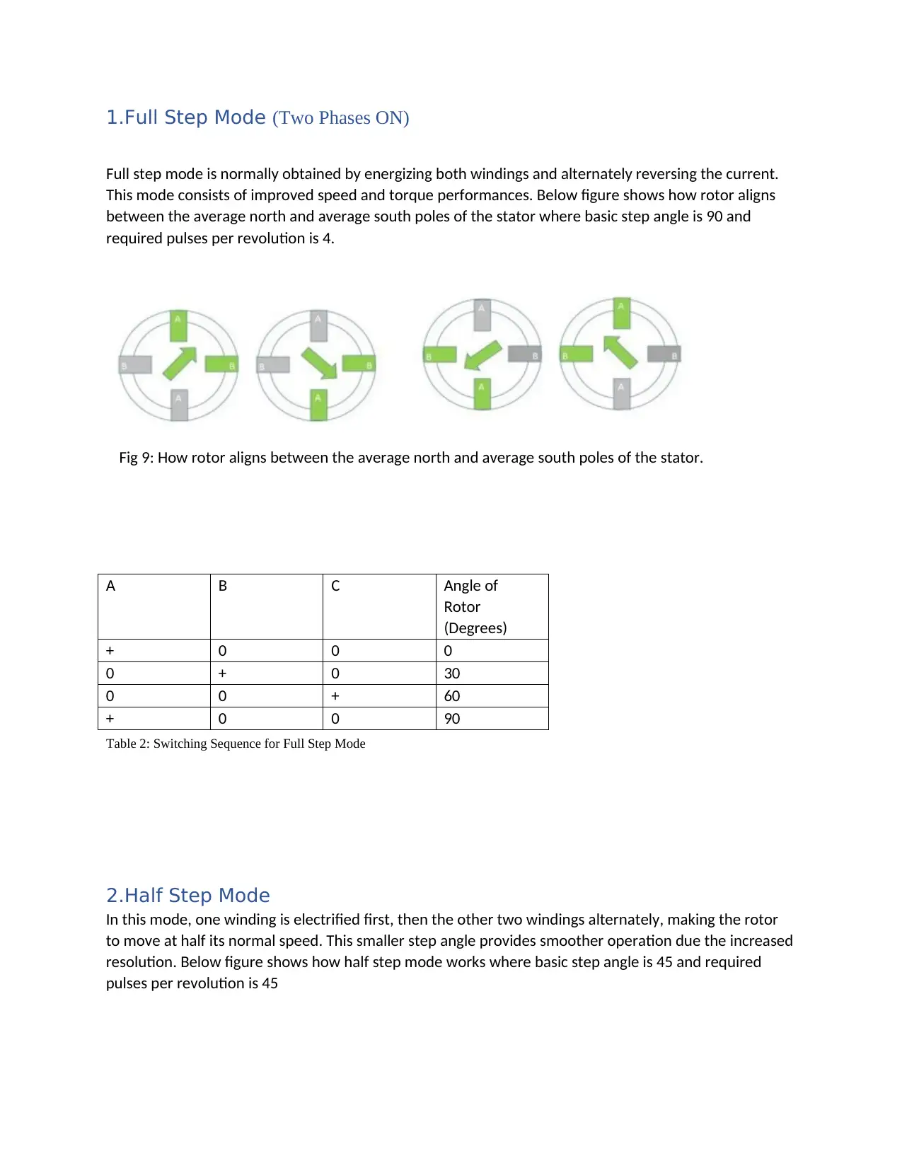
1.Full Step Mode (Two Phases ON)
Full step mode is normally obtained by energizing both windings and alternately reversing the current.
This mode consists of improved speed and torque performances. Below figure shows how rotor aligns
between the average north and average south poles of the stator where basic step angle is 90 and
required pulses per revolution is 4.
Fig 9: How rotor aligns between the average north and average south poles of the stator.
Table 2: Switching Sequence for Full Step Mode
2.Half Step Mode
In this mode, one winding is electrified first, then the other two windings alternately, making the rotor
to move at half its normal speed. This smaller step angle provides smoother operation due the increased
resolution. Below figure shows how half step mode works where basic step angle is 45 and required
pulses per revolution is 45
A B C Angle of
Rotor
(Degrees)
+ 0 0 0
0 + 0 30
0 0 + 60
+ 0 0 90
Paraphrase This Document
Need a fresh take? Get an instant paraphrase of this document with our AI Paraphraser
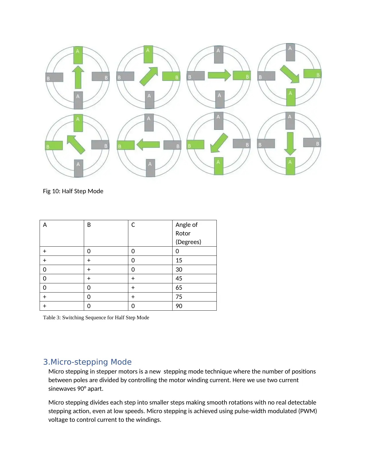
Fig 10: Half Step Mode
Table 3: Switching Sequence for Half Step Mode
3.Micro-stepping Mode
Micro stepping in stepper motors is a new stepping mode technique where the number of positions
between poles are divided by controlling the motor winding current. Here we use two current
sinewaves 90° apart.
Micro stepping divides each step into smaller steps making smooth rotations with no real detectable
stepping action, even at low speeds. Micro stepping is achieved using pulse-width modulated (PWM)
voltage to control current to the windings.
A B C Angle of
Rotor
(Degrees)
+ 0 0 0
+ + 0 15
0 + 0 30
0 + + 45
0 0 + 65
+ 0 + 75
+ 0 0 90
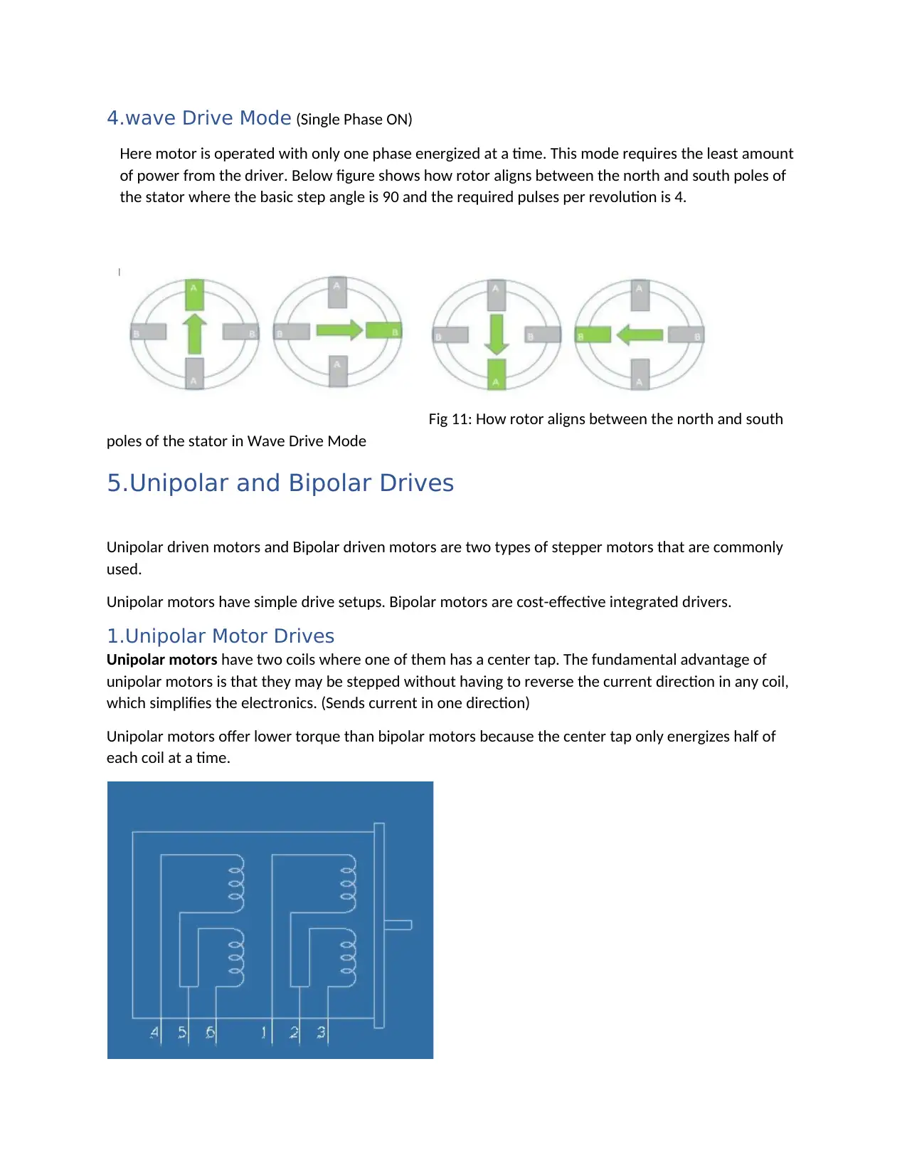
4.wave Drive Mode (Single Phase ON)
Here motor is operated with only one phase energized at a time. This mode requires the least amount
of power from the driver. Below figure shows how rotor aligns between the north and south poles of
the stator where the basic step angle is 90 and the required pulses per revolution is 4.
Fig 11: How rotor aligns between the north and south
poles of the stator in Wave Drive Mode
5.Unipolar and Bipolar Drives
Unipolar driven motors and Bipolar driven motors are two types of stepper motors that are commonly
used.
Unipolar motors have simple drive setups. Bipolar motors are cost-effective integrated drivers.
1.Unipolar Motor Drives
Unipolar motors have two coils where one of them has a center tap. The fundamental advantage of
unipolar motors is that they may be stepped without having to reverse the current direction in any coil,
which simplifies the electronics. (Sends current in one direction)
Unipolar motors offer lower torque than bipolar motors because the center tap only energizes half of
each coil at a time.
⊘ This is a preview!⊘
Do you want full access?
Subscribe today to unlock all pages.
Trusted by 1+ million students worldwide
1 out of 14
Related Documents


Your All-in-One AI-Powered Toolkit for Academic Success.
+13062052269
info@desklib.com
Available 24*7 on WhatsApp / Email
![[object Object]](/_next/static/media/star-bottom.7253800d.svg)
Unlock your academic potential
Copyright © 2020–2026 A2Z Services. All Rights Reserved. Developed and managed by ZUCOL.