Comparative Study: Stirling Engine and Solar Energy Applications
VerifiedAdded on 2022/08/24
|24
|4481
|25
Report
AI Summary
This report provides a detailed examination of the Stirling engine, beginning with its historical background and evolution. It then explores the differences between photovoltaic solar and solar thermal technologies, including their installation processes and operational principles. The report delves into the workings of the Stirling engine, covering its operational cycles and the key components of a solar thermal Stirling engine system, such as parabolic dishes, generators, and solar tracking systems. Additionally, it explains the functionality of two dual-axis systems and presents a comparative analysis of different Stirling engine types (Alpha, Beta, and Gamma), including their advantages, disadvantages, and operational characteristics. Diagrams and tables are used to illustrate the different systems and components, and all information is referenced from books.
1
STIRLING ENGINE
Stirling Engine Background
The engine was discovered by Robert Stirling (Scotland minister) in the year
1816.He was hoping on finding the efficient and safe way of substituting the
steam engine. The engine was incorporated with the features of phase shift
between the piston and displacer in form of reversed heat engine. The engine also
included the cyclic of cooling and heating of internal gas by use of external source
of heat. Stirling initially regarded the sterling engine as a continuous motion
device of 2nd kind i.e. heat energy supplied is transformed to work despite the
original air engine didn’t include the system for cooling. Due to discovery of a
powerful internal heating engine in the 19th century, Stirling discovery was
abandoned. The steam engine was introduced, even though the Stirling engine had
more benefits compared to steam engine. The operational cost of Stirling engine
were relatively low compared to that of steam engine. The steam engines were
also prone to explosions failures. The main limitation of Stirling engine is the
affinity of failing when the cylinder is heated and becomes too hot. Though the
advancement made to reduce the failing tendency, tough competition from other
internal heating engines forced it out of market scene. Recently the researchers
are doing much studies on the Stirling engines, design techniques that are applied
in low temperature Stirling engines [1].
Differences between Photovoltaic solar and solar thermal technologies
PV solar technology involves conversion of solar radiations (sunlight) to D.C
electricity by use of semiconductors. When the solar hits semiconductors with PV
Paraphrase This Document
Need a fresh take? Get an instant paraphrase of this document with our AI Paraphraser
2
cell, the electrons are dislodged to produce electric current. The technology is
usually employed on solar panels. Photovoltaic cells are connected to another and
attached to a module .Multiple segments are wired together forming arrays, which
is scaled down to yield the power required. Solar thermal technology involves
harvesting solar energy for heat (thermal energy).The technology consists of
parabolic or flat collectors which concentrates the solar radiation by use of lenses
and mirrors. The process utilizes solar energy to provide heat for water heating,
space heating, cooking, and crop drying [2].
Installation
PV solar
Photovoltaic solar system consists of solar module, solar inverter mounting
system and computerized controller. Solar module produces Dc electricity from
solar radiations .Inverter converts produced electricity into alternating current
which is used domestically. Computerized controller manages the system and
ensures maximum performance .For off-grid system the battery is used. Solar
modules are mounted at the roof tops so that the panel receives maximum solar
radiations. Nevertheless .if the roof top installation is not applicable, the panels
are mounted on the ground where no objects blocking the sunlight. The solar
panels are installed using the following steps;
a. Scaffold set up –Scaffolding is erected to guarantee safety for the whole
process of installation.
b. Installation of panel mounts-The mounting system is set up to support the
base of the panel. The mounting system is tilted in an angle that ranges
between 18o to 36o for maximum solar radiation exposure.
3
c. Installation of solar module – solar panels are fitted on the mounting
structure. The nuts and bolts are tightened to make the module to be stable.
d. Wiring the solar panels –Electrical wiring by use of MC4 connectors is
done.
e. Installation of solar inverter- The inverter is connected to the system. It is
installed indoor or outdoor near the main panel. Inverters are most efficient
when reserved in a cooler place.
f. Bonding the solar inverter and battery –The solar inverter is connected to
the battery. The battery acts as a storage system for the system.
g. Connection of the inverter to consumer unit. –The inverter is connected to
consumer unit to produce electricity. A meter is connected to the monitor to
measure the actual electricity amount produced by the panel.
h. Start and test of system –This is the final step of the installation which
switches on power and test the installed system [3].
Solar thermal
Solar thermal installation involves a number of steps in connecting the system
until it works effectively. Components connected involves storage tank, evacuated
tube collector, pump station, heat transfer fluid, controller, heat dissipation and
solar flex. The evacuated collector is installed on top of roofs to maximize the
amount of solar radiation absorbed. The steps followed in installation includes;
a. Marking the roof penetrations-Outlining is done by use of marking pen or
chalk on where the tube is to be attached on top roof.
⊘ This is a preview!⊘
Do you want full access?
Subscribe today to unlock all pages.
Trusted by 1+ million students worldwide
4
b. Location of rafters –Mark off along the pen marking lines to show where the
rafters intersect, usually the spacing of 12" or 16" is used. For each evacuated
tube the intersection is chosen to match the mounting marks.
c. Mounting and assembly of frame- Penetration points marked are screwed by
a frame along with rubber band to rafters by using 3/8 x 3 1/2 lag screws of
stainless steel.
d. Collector manifold and connection-The manifold is attached to the
assembled frame and it rests on clips on top of the frame. There are 3 clips
which slides back the manifold, and bolted into place to secure it to the frame
without penetration.
e. Heat dissipation /installation of flush mount – Roof trusses are located at
16" or 24" on the marked center and then screwed by use of lag bolt support
in 5/8" socket.
f. Angle frame installation –using 6" in length threated rod with threated nuts
followed by nylon washer. The rod can be replaced with 2 ½” bolt.
g. Valve installation diversion –Thermostatic diversion valve is used to close
and open the flow to and fro heat dissipater. The process is carried out without
power and valve is heat driven .The valve opens when a given temperature in
the loop is reached, permitting flow through dissipation loop.
h. Storage tank and pump installation –The storage tank is positioned in a
place near the appropriate power supply for the backup. The pump
components are re-assembled to brackets .Starting with installation of cover
over mounting bracket [4].
Paraphrase This Document
Need a fresh take? Get an instant paraphrase of this document with our AI Paraphraser
5
i. Installation of expansion tank- The expansion tank brackets are amounted in
a suitable location near to the pump station. Brass double valves is connected
to expansion tank by use of green washers.
j. Controller installation -Solar controller is mounted to the pump station front.
Controller routes power cord is mounted at the lower right insulation hole.
Temperature probe is fastened to the sensor at the bottom tank.
k. Filling and flushing test-Faucet of hot water is 1st opened within the
facilities. Then water isolation valve is opened to solar tank. After the filling,
the faucets are closed and inspection of threated fitting is done and joints for
leakages are soldered. Then the system is flushed to test for workability.
l. Purging air installation-purging air controller is installed and they are
programmed thus, the do not require adjustments in their application.
m. Set of flow rate –Pump flowing rate is set by use of site gage situated at the
bottom of the pump. The gage shows the flow rate [3].
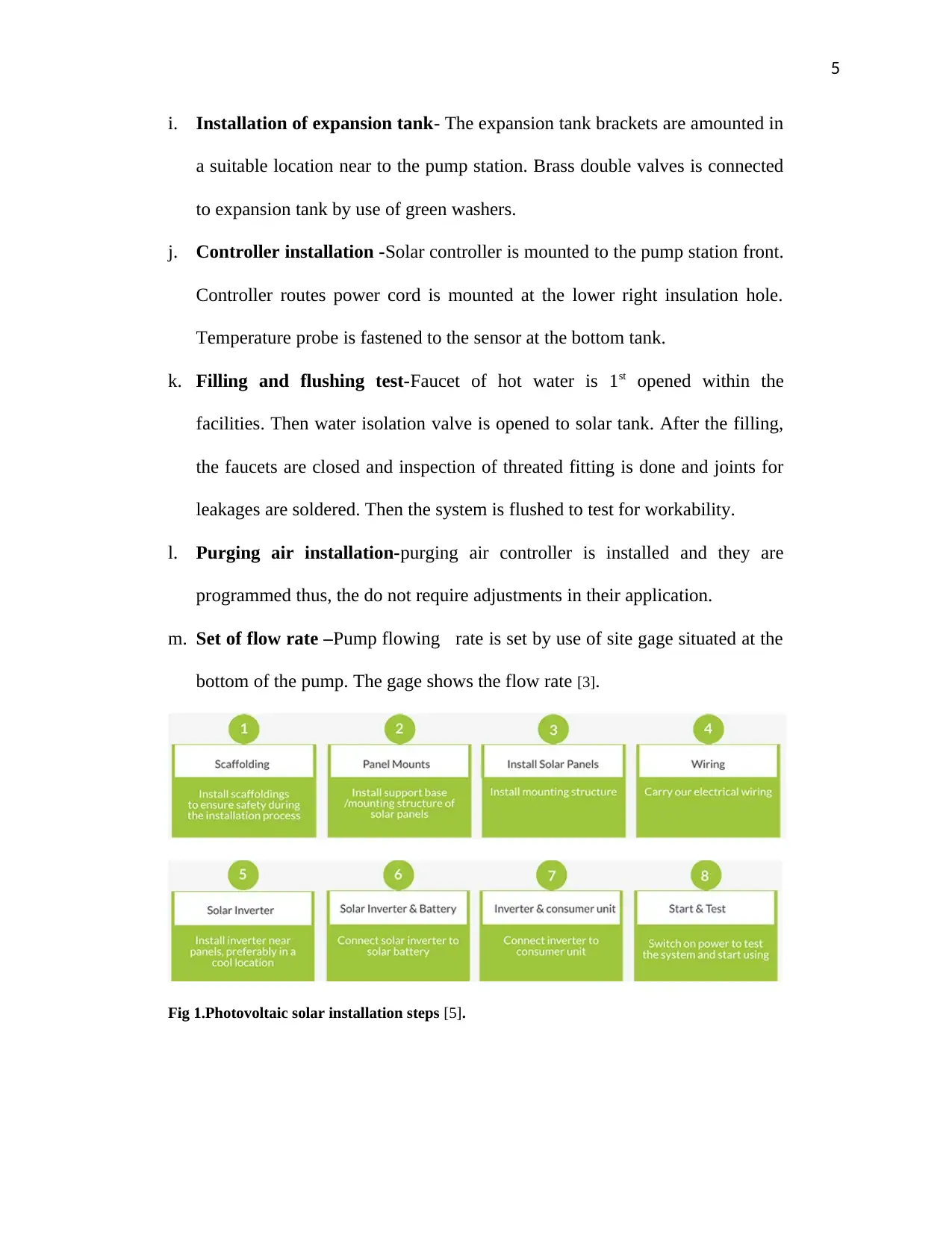
Fig 1.Photovoltaic solar installation steps [5].
i. Installation of expansion tank- The expansion tank brackets are amounted in
a suitable location near to the pump station. Brass double valves is connected
to expansion tank by use of green washers.
j. Controller installation -Solar controller is mounted to the pump station front.
Controller routes power cord is mounted at the lower right insulation hole.
Temperature probe is fastened to the sensor at the bottom tank.
k. Filling and flushing test-Faucet of hot water is 1st opened within the
facilities. Then water isolation valve is opened to solar tank. After the filling,
the faucets are closed and inspection of threated fitting is done and joints for
leakages are soldered. Then the system is flushed to test for workability.
l. Purging air installation-purging air controller is installed and they are
programmed thus, the do not require adjustments in their application.
m. Set of flow rate –Pump flowing rate is set by use of site gage situated at the
bottom of the pump. The gage shows the flow rate [3].
Fig 1.Photovoltaic solar installation steps [5].
6
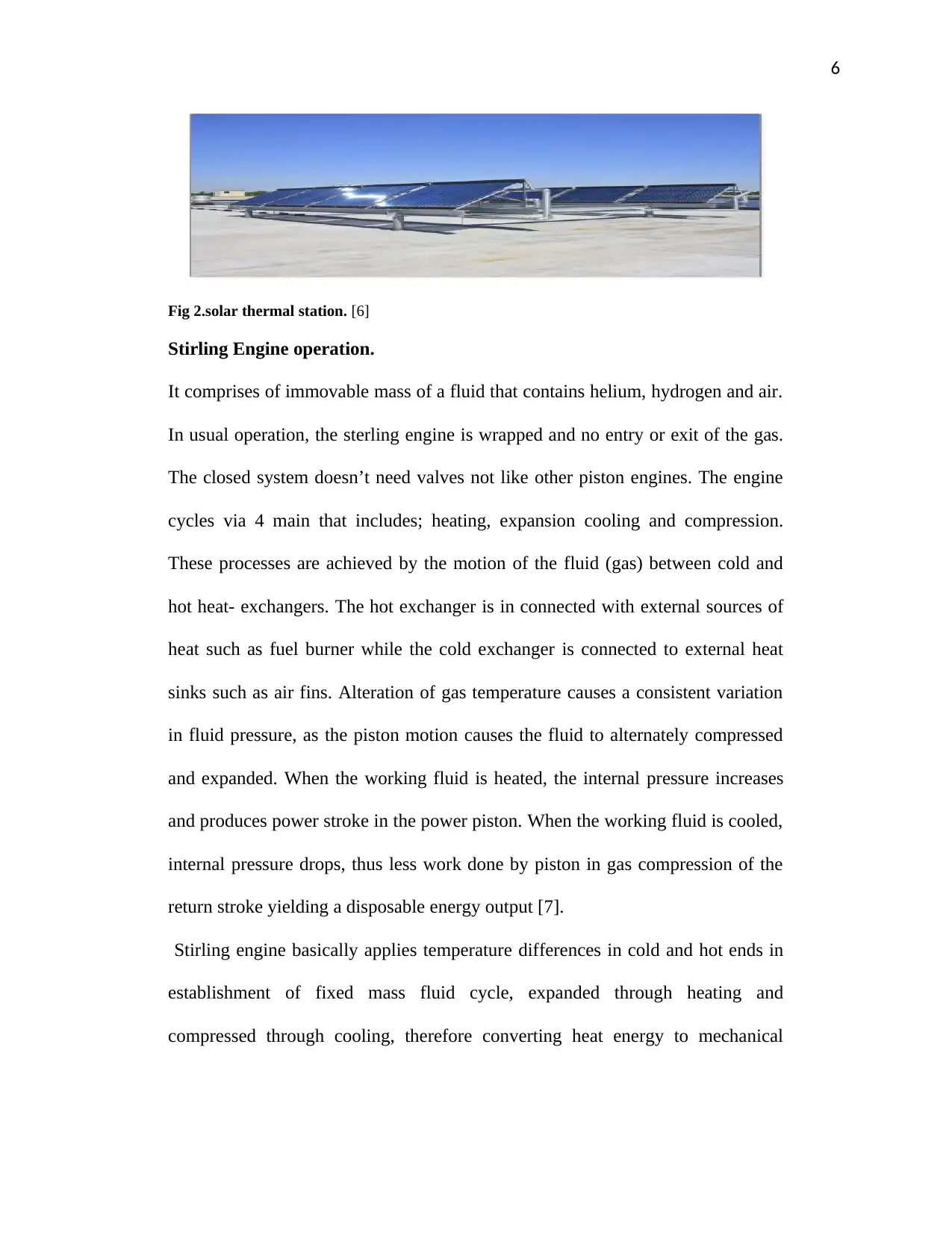
Fig 2.solar thermal station. [6]
Stirling Engine operation.
It comprises of immovable mass of a fluid that contains helium, hydrogen and air.
In usual operation, the sterling engine is wrapped and no entry or exit of the gas.
The closed system doesn’t need valves not like other piston engines. The engine
cycles via 4 main that includes; heating, expansion cooling and compression.
These processes are achieved by the motion of the fluid (gas) between cold and
hot heat- exchangers. The hot exchanger is in connected with external sources of
heat such as fuel burner while the cold exchanger is connected to external heat
sinks such as air fins. Alteration of gas temperature causes a consistent variation
in fluid pressure, as the piston motion causes the fluid to alternately compressed
and expanded. When the working fluid is heated, the internal pressure increases
and produces power stroke in the power piston. When the working fluid is cooled,
internal pressure drops, thus less work done by piston in gas compression of the
return stroke yielding a disposable energy output [7].
Stirling engine basically applies temperature differences in cold and hot ends in
establishment of fixed mass fluid cycle, expanded through heating and
compressed through cooling, therefore converting heat energy to mechanical
⊘ This is a preview!⊘
Do you want full access?
Subscribe today to unlock all pages.
Trusted by 1+ million students worldwide
7
energy. The thermal efficiency of engine is high when the heat difference between
cold and hot sources are greater. Maximum efficiency is equal to Carnot cycle [8].
Solar Thermal Stirling Engine system.
Stirling Engine
Is an engine that works on heat cycle using compressible fluid like, helium,
nitrogen, air and hydrogen. It is designed by either alpha or beta which are the
common schemes. The Stirling engine receives heat that is directed from the
parabolic dish to generate temperature differences in cold and hot ends in
establishment of fixed mass fluid cycle, expanded through heating and
compressed through cooling, therefore converting heat energy to mechanical
energy. The thermal efficiency of the engine is high when the temperature
differences between cold and hot sources are greater [8].
Parabolic dish components.
The system consists of parabolic dish structure that has a parabolic reflector in
dish form with a supporting edifice .Stirling engine is mounted in the
concentrating side of the dish to receive solar radiations and generate electrical
power. Solar dish directs the sunlight automatically by use of tracking system
(control system) [9].
Paraphrase This Document
Need a fresh take? Get an instant paraphrase of this document with our AI Paraphraser
8
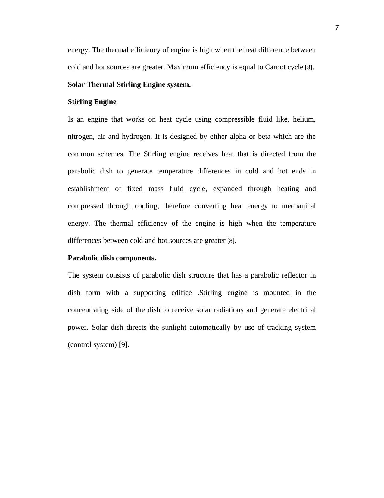
Fig 3.Parabolic dish [4]
Solar heating is incorporated with the parabolic dish that is attached to the engine.
The solar concentrator redirects and focuses the sun radiations into a small zone
leading to concentration. The intensity of concentrated solar energy to be
magnified to the receiver. The dish are used in generating steam in Stirling
engines. The dish must have the following properties;
i. Durable to temperature and moisture.
ii. Reasonable weight.
iii. Hard against wind load and deflection.
iv. Flexible
v. Long lasting
vi. Operative reflecting material [10].
Generator (12V DC motor)
It serves a crucial role in engine system as it acts as a reservoir of thermal energy,
stores the energy in one part of the cycle and reimports that energy to working
9
fluid in rest of the cycle. Internal in heat exchanger, heat is temporary stored in
the regenerator which is situated between cold and hot spaces of the working
fluid. It retains heat enabling thermal cycle efficiency of the system. Absence of
the generator fluid that flows from hot part to cold part would lose a huge portion
of enthalpy and heated up when flowing to hot side resulting to poor efficiency.
The motor also actuates the electronic system to rotate the collector so that it can
always point to the sun direction. These processes are achieved by the motion of
the fluid (gas) between cold and hot heat- exchangers. The hot exchanger is in
connected with external sources of heat such as fuel burner while the cold
exchanger is connected to external heat sinks such as air fins. Alteration of gas
temperature causes a consistent variation in fluid pressure, as the piston motion
causes the fluid to alternately compressed and expanded. When the working fluid
is heated, the internal pressure increases and produces power stroke in the power
piston [11].
Solar Tracking system
It is system applied for orientation of solar dish towards the solar beams direction.
The system ensures that concentrated solar radiation is redirected to the powered
engine which is the Stirling engine. It works by utilization of 3 LDRs.The 1st LDR
detects the state of focus while the 2nd and 3rd designed to detect the absence or the
presence of cloudy cover that distinguish between day time and night time.
Output signal from the 3 LDR are fed to electronic control structure that is
actuated by a low velocity motor of 12V direct current in a way that it rotates the
collector and remains pointed toward the sun [12].
⊘ This is a preview!⊘
Do you want full access?
Subscribe today to unlock all pages.
Trusted by 1+ million students worldwide
10
2 dual axis system
In this system 5 LDR sensors and a control box is used as gear mechanism with
the DC motor. 5LDR detects light which acts as 5 sensors mounted to the dish and
enclosed. Sensors are set up in a way that LDR1 and LDR2 are used to track
horizontal rays or radiations to drive horizontal locating motor. LDR3 and LDR4
tracks solar radiations vertically for driving the locating motor.LDR5 detects the
session i.e. whether the day is or not. The information produced by the sensors is
processed by the fuzzy logic. All the operation are done by the control box fused
with a microcontroller and motor ICs control processes. Both motors for
horizontal and vertical movement ensures suitable tracking of the parabolic dish
in any solar direction with respect to North-South or East –West [1].
Lead acid battery (12 V)
The battery is used to store the energy produced in the system.it is connected to
the inverter to enable convert the Dc energy to AC power which is used in the
system. The power generated by the engine is taped by the mounted dynamo to
flywheel and then directed to the battery for storage [13].
AC invertor (12 -240 V)
The inverter is connected to the system. It is installed indoor or outdoor near the
main solar dish. Inverters are most efficient when reserved in a cooler place. It
converts stored DC power stored in the battery to AC which is used in the system
[13].
Stirling engine operation (Details)
The operational configuration of the engine differs from each other. The
configurations are differentiated to move the working fluid moves between cold
Paraphrase This Document
Need a fresh take? Get an instant paraphrase of this document with our AI Paraphraser
11
and hot cylinder sides. Gamma type uses mechanical displacer in pushing the
fluid between cold and hot cylinder sides. The displacer is boarded in a distinct
cylinder enabling mechanical design. Alpha type uses independent cylinders in
design and a working fluid is driven between cold and hot spaces. Beta type uses
insulated displacer in the design to push the fluid between the cold and hot
cylinder sides [8].
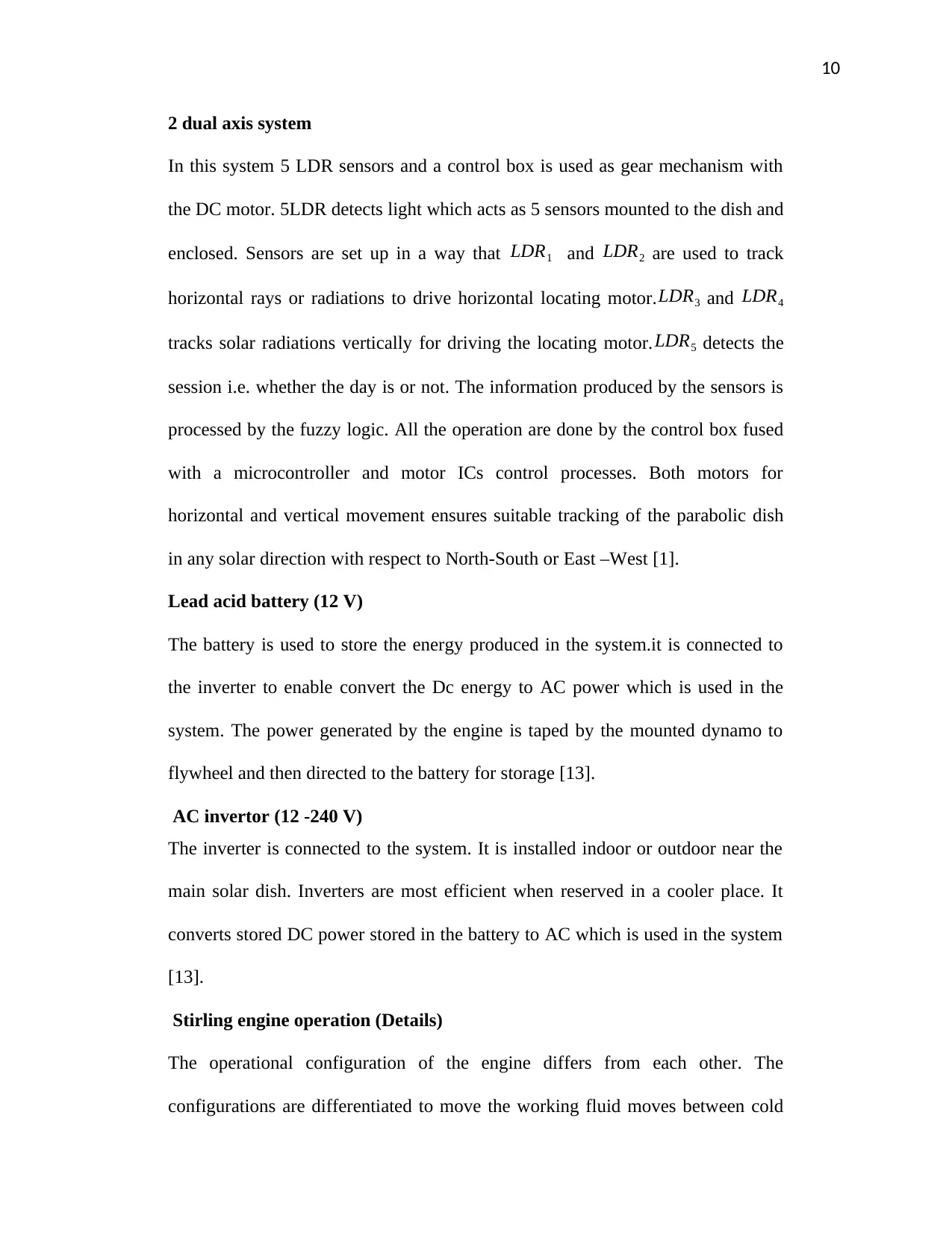
a) Gamma configuration
It is a beta Sterling where power piston is mounted in a distinct cylinder in
combination with displacer piston, still coupled to sameflywheel.The working
fluid in 2 cylinder flows freely between them and remains a single body. Gamma
configuration produces a low compression ratio which are mechanical simpler [8].
Fig 4.Gamma Stirling [8]
Gamma Stirling engine
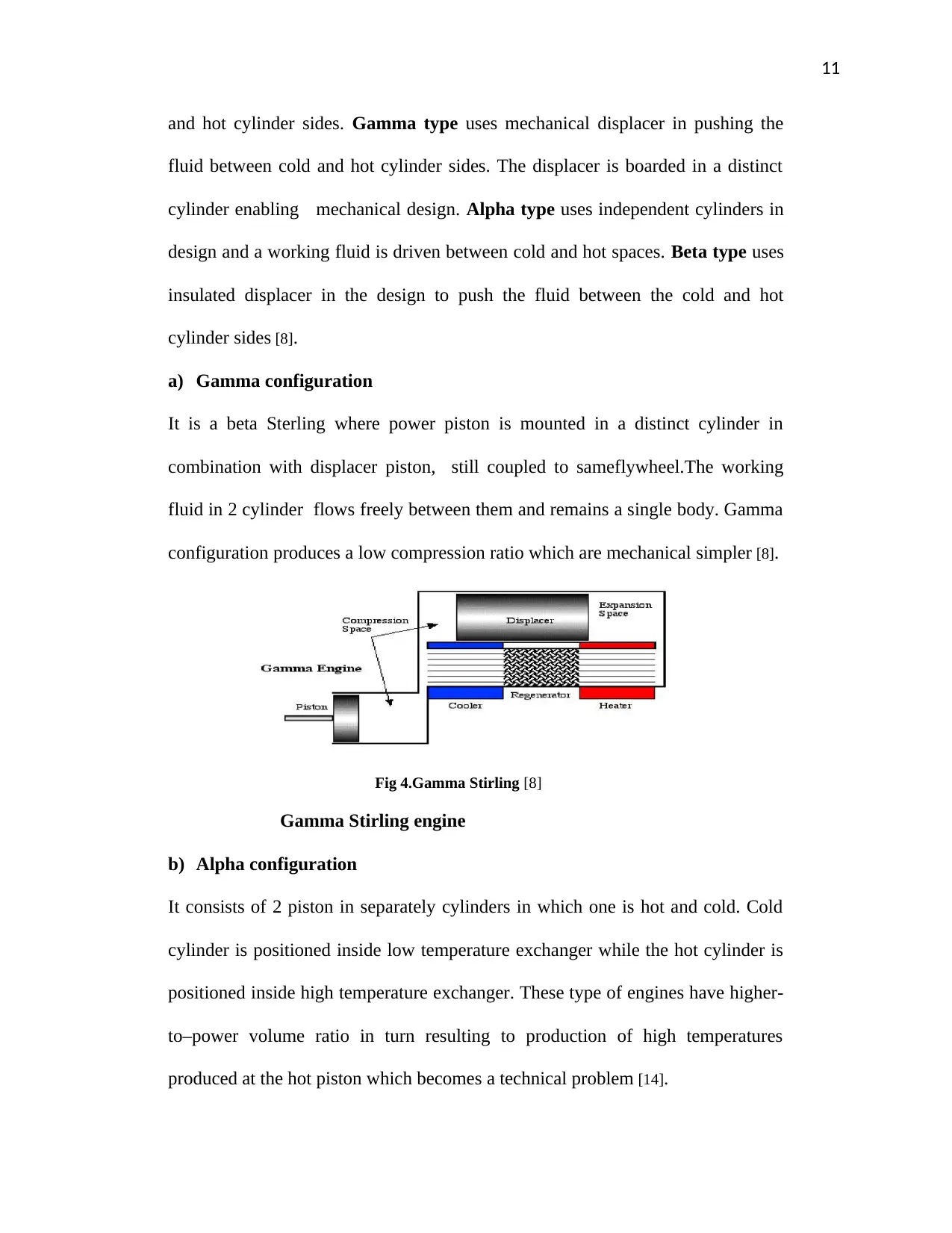
b) Alpha configuration
It consists of 2 piston in separately cylinders in which one is hot and cold. Cold
cylinder is positioned inside low temperature exchanger while the hot cylinder is
positioned inside high temperature exchanger. These type of engines have higher-
to–power volume ratio in turn resulting to production of high temperatures
produced at the hot piston which becomes a technical problem [14].
and hot cylinder sides. Gamma type uses mechanical displacer in pushing the
fluid between cold and hot cylinder sides. The displacer is boarded in a distinct
cylinder enabling mechanical design. Alpha type uses independent cylinders in
design and a working fluid is driven between cold and hot spaces. Beta type uses
insulated displacer in the design to push the fluid between the cold and hot
cylinder sides [8].
a) Gamma configuration
It is a beta Sterling where power piston is mounted in a distinct cylinder in
combination with displacer piston, still coupled to sameflywheel.The working
fluid in 2 cylinder flows freely between them and remains a single body. Gamma
configuration produces a low compression ratio which are mechanical simpler [8].
Fig 4.Gamma Stirling [8]
Gamma Stirling engine
b) Alpha configuration
It consists of 2 piston in separately cylinders in which one is hot and cold. Cold
cylinder is positioned inside low temperature exchanger while the hot cylinder is
positioned inside high temperature exchanger. These type of engines have higher-
to–power volume ratio in turn resulting to production of high temperatures
produced at the hot piston which becomes a technical problem [14].
12
Fig 5.Alpha Stirling [14]
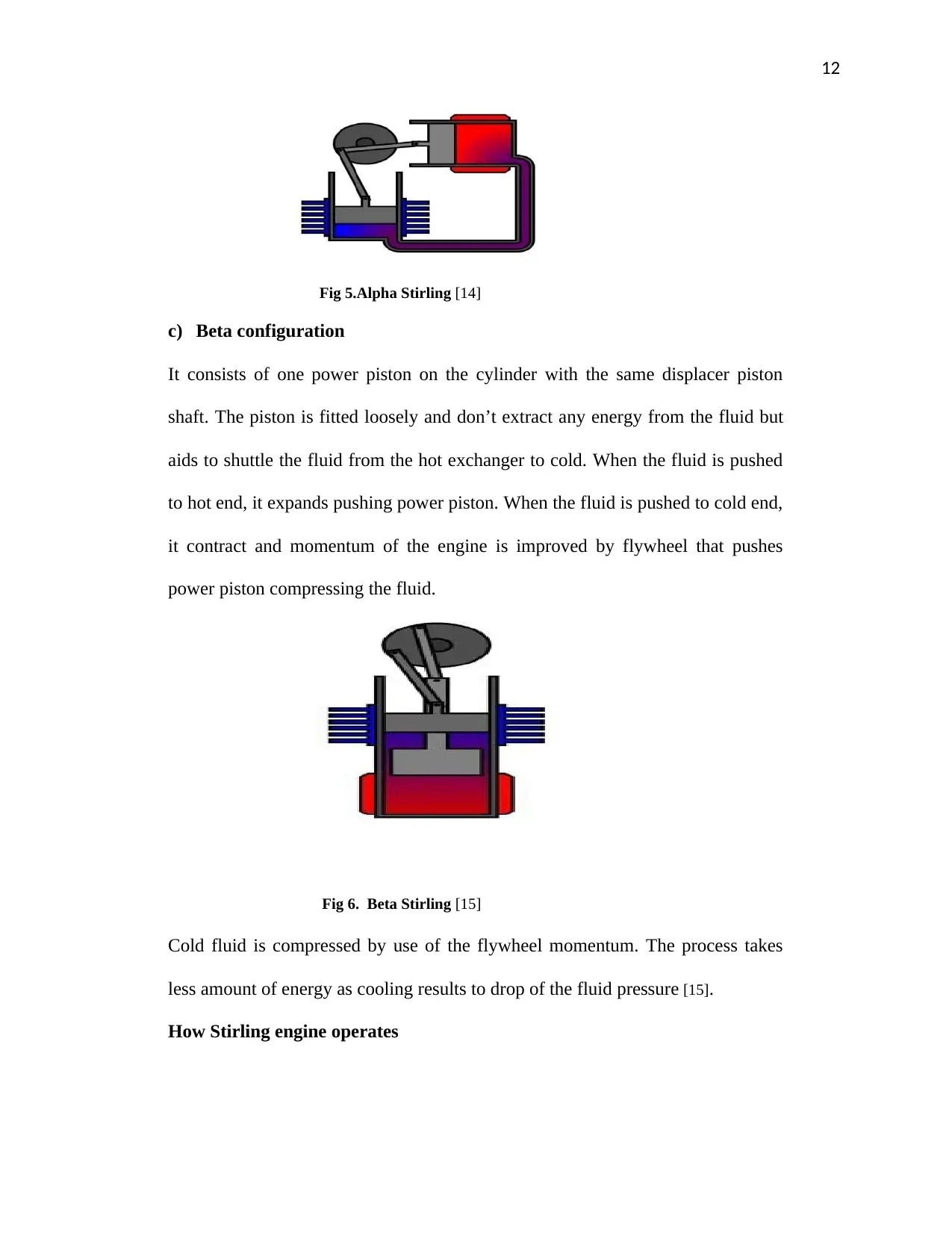
c) Beta configuration
It consists of one power piston on the cylinder with the same displacer piston
shaft. The piston is fitted loosely and don’t extract any energy from the fluid but
aids to shuttle the fluid from the hot exchanger to cold. When the fluid is pushed
to hot end, it expands pushing power piston. When the fluid is pushed to cold end,
it contract and momentum of the engine is improved by flywheel that pushes
power piston compressing the fluid.
Fig 6. Beta Stirling [15]
Cold fluid is compressed by use of the flywheel momentum. The process takes
less amount of energy as cooling results to drop of the fluid pressure [15].
How Stirling engine operates
Fig 5.Alpha Stirling [14]
c) Beta configuration
It consists of one power piston on the cylinder with the same displacer piston
shaft. The piston is fitted loosely and don’t extract any energy from the fluid but
aids to shuttle the fluid from the hot exchanger to cold. When the fluid is pushed
to hot end, it expands pushing power piston. When the fluid is pushed to cold end,
it contract and momentum of the engine is improved by flywheel that pushes
power piston compressing the fluid.
Fig 6. Beta Stirling [15]
Cold fluid is compressed by use of the flywheel momentum. The process takes
less amount of energy as cooling results to drop of the fluid pressure [15].
How Stirling engine operates
⊘ This is a preview!⊘
Do you want full access?
Subscribe today to unlock all pages.
Trusted by 1+ million students worldwide
1 out of 24
Related Documents


Your All-in-One AI-Powered Toolkit for Academic Success.
+13062052269
info@desklib.com
Available 24*7 on WhatsApp / Email
![[object Object]](/_next/static/media/star-bottom.7253800d.svg)
Unlock your academic potential
Copyright © 2020–2026 A2Z Services. All Rights Reserved. Developed and managed by ZUCOL.