Structural Analysis: Stool Footrest, I-Beam, and Snow Plough Frame
VerifiedAdded on 2023/04/21
|13
|2388
|234
Homework Assignment
AI Summary
This document presents a comprehensive solution to a civil engineering structural analysis assignment. The assignment covers several key concepts, including the analysis of a stool footrest, an asymmetric I-beam, a snow plough mounting frame, and a fitness bench. The solution includes qualitative analysis, free body diagrams, shear force and bending moment diagrams, calculations of centroid and second moment of area, and the application of static equilibrium principles to determine reaction forces and bending stresses. The solutions demonstrate the use of manual calculations, spreadsheet analysis, and the application of engineering theory of bending. Detailed steps and explanations are provided for each problem, offering a thorough understanding of structural analysis principles.
First Name Last Name
Instructor
Civil engineering
12 January 2019
Structural Analysis
Question 1
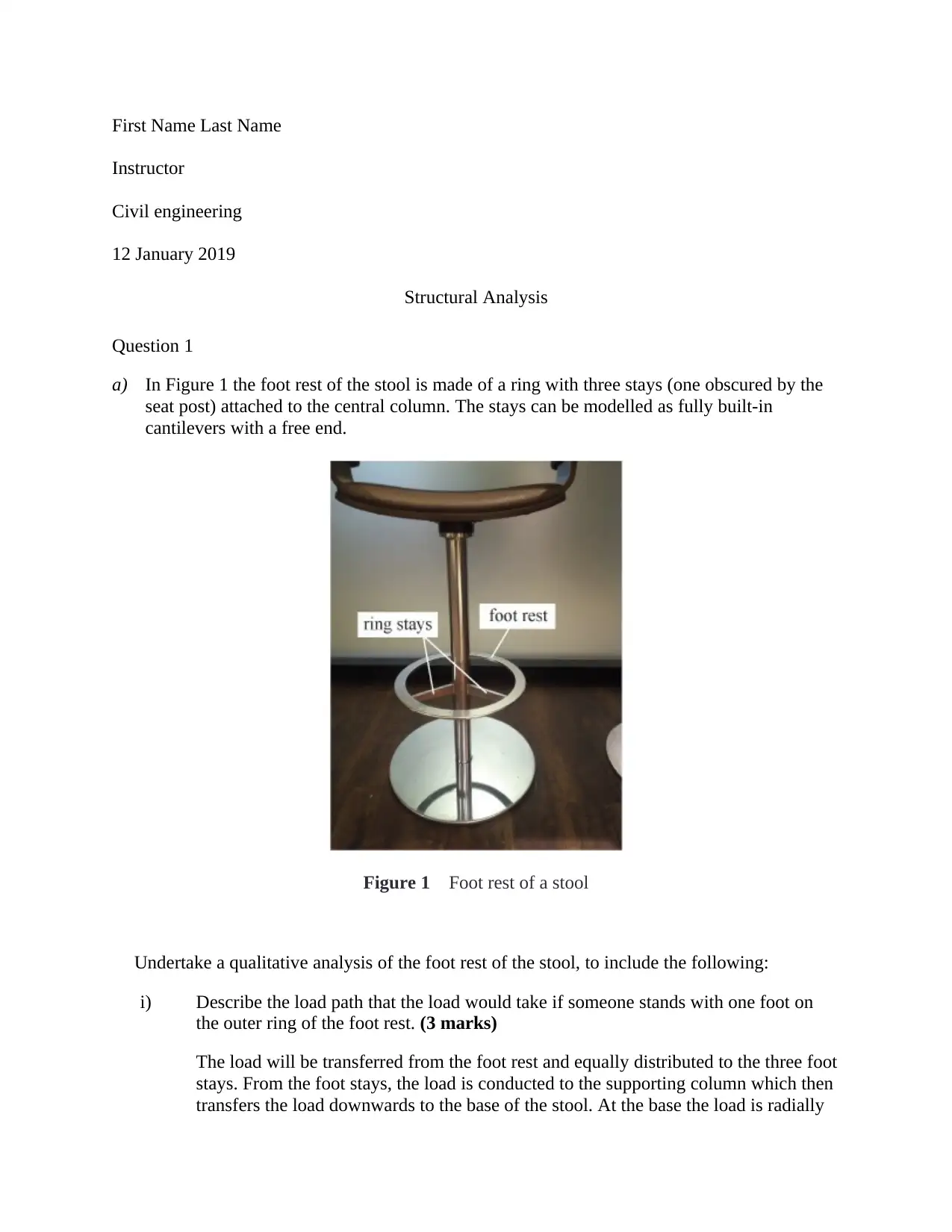
a) In Figure 1 the foot rest of the stool is made of a ring with three stays (one obscured by the
seat post) attached to the central column. The stays can be modelled as fully built-in
cantilevers with a free end.
Figure 1 Foot rest of a stool
Undertake a qualitative analysis of the foot rest of the stool, to include the following:
i) Describe the load path that the load would take if someone stands with one foot on
the outer ring of the foot rest. (3 marks)
The load will be transferred from the foot rest and equally distributed to the three foot
stays. From the foot stays, the load is conducted to the supporting column which then
transfers the load downwards to the base of the stool. At the base the load is radially
Instructor
Civil engineering
12 January 2019
Structural Analysis
Question 1
a) In Figure 1 the foot rest of the stool is made of a ring with three stays (one obscured by the
seat post) attached to the central column. The stays can be modelled as fully built-in
cantilevers with a free end.
Figure 1 Foot rest of a stool
Undertake a qualitative analysis of the foot rest of the stool, to include the following:
i) Describe the load path that the load would take if someone stands with one foot on
the outer ring of the foot rest. (3 marks)
The load will be transferred from the foot rest and equally distributed to the three foot
stays. From the foot stays, the load is conducted to the supporting column which then
transfers the load downwards to the base of the stool. At the base the load is radially
Paraphrase This Document
Need a fresh take? Get an instant paraphrase of this document with our AI Paraphraser
transmitted to the edges of the foot base and into the slap upon which the stool rests.
Load from the slabs are distributed together with other loads, including dead and live
loads to the foundation or columns and walls respectively.
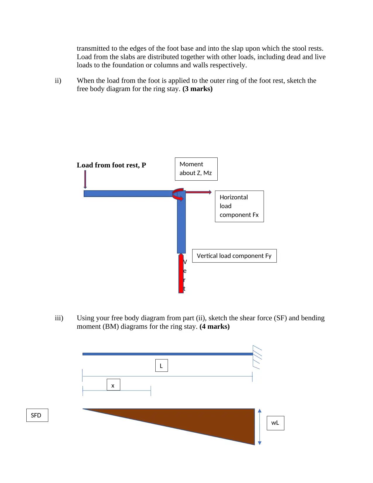
ii) When the load from the foot is applied to the outer ring of the foot rest, sketch the
free body diagram for the ring stay. (3 marks)
Load from foot rest, P
iii) Using your free body diagram from part (ii), sketch the shear force (SF) and bending
moment (BM) diagrams for the ring stay. (4 marks)
V
e
r
t
Horizontal
load
component Fx
Vertical load component Fy
L
x
wL
SFD
Moment
about Z, Mz
Load from the slabs are distributed together with other loads, including dead and live
loads to the foundation or columns and walls respectively.
ii) When the load from the foot is applied to the outer ring of the foot rest, sketch the
free body diagram for the ring stay. (3 marks)
Load from foot rest, P
iii) Using your free body diagram from part (ii), sketch the shear force (SF) and bending
moment (BM) diagrams for the ring stay. (4 marks)
V
e
r
t
Horizontal
load
component Fx
Vertical load component Fy
L
x
wL
SFD
Moment
about Z, Mz
Question 2
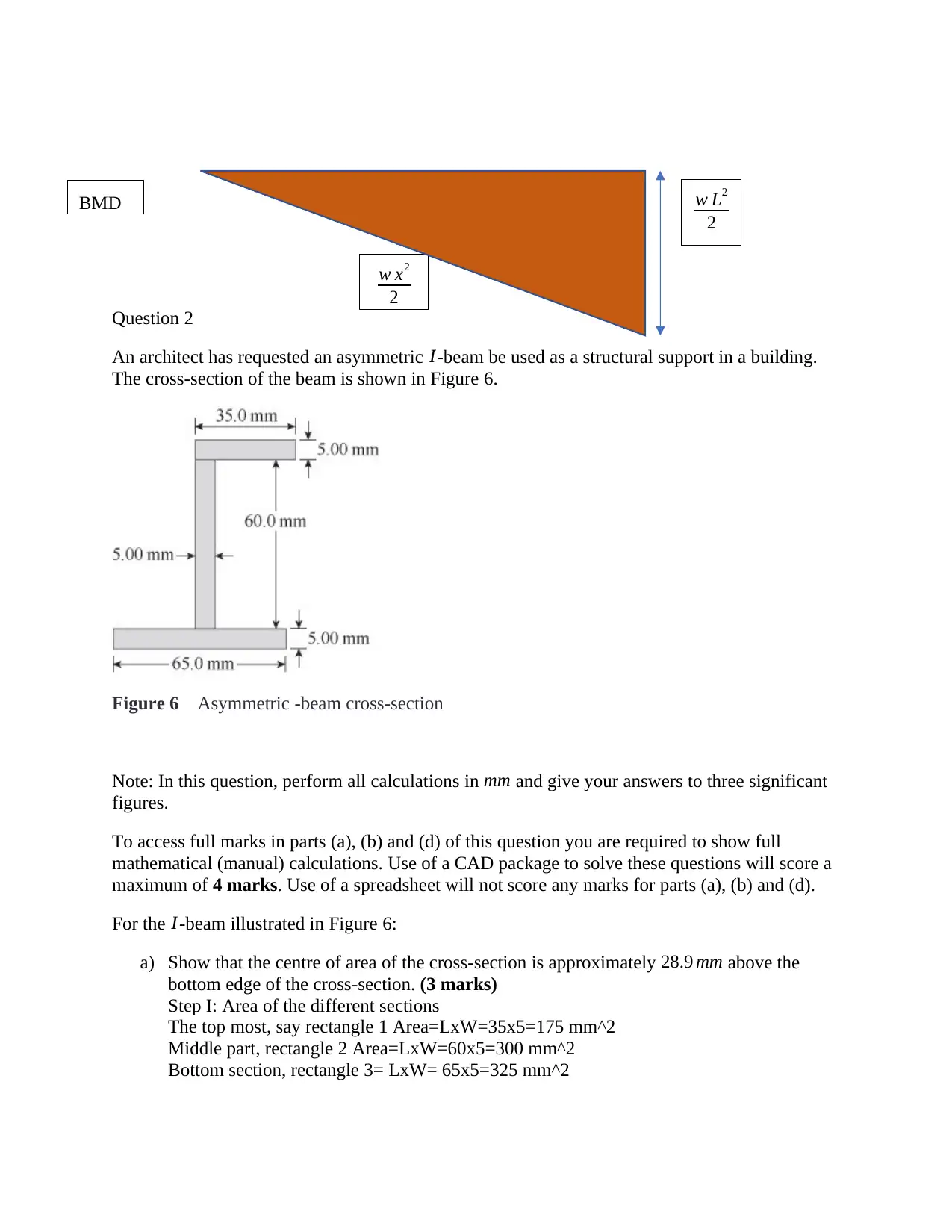
An architect has requested an asymmetric I-beam be used as a structural support in a building.
The cross-section of the beam is shown in Figure 6.
Figure 6 Asymmetric -beam cross-section
Note: In this question, perform all calculations in mm and give your answers to three significant
figures.
To access full marks in parts (a), (b) and (d) of this question you are required to show full
mathematical (manual) calculations. Use of a CAD package to solve these questions will score a
maximum of 4 marks. Use of a spreadsheet will not score any marks for parts (a), (b) and (d).
For the I-beam illustrated in Figure 6:
a) Show that the centre of area of the cross-section is approximately 28.9 mm above the
bottom edge of the cross-section. (3 marks)
Step I: Area of the different sections
The top most, say rectangle 1 Area=LxW=35x5=175 mm^2
Middle part, rectangle 2 Area=LxW=60x5=300 mm^2
Bottom section, rectangle 3= LxW= 65x5=325 mm^2
w L2
2
w x2
2
BMD
⊘ This is a preview!⊘
Do you want full access?
Subscribe today to unlock all pages.
Trusted by 1+ million students worldwide
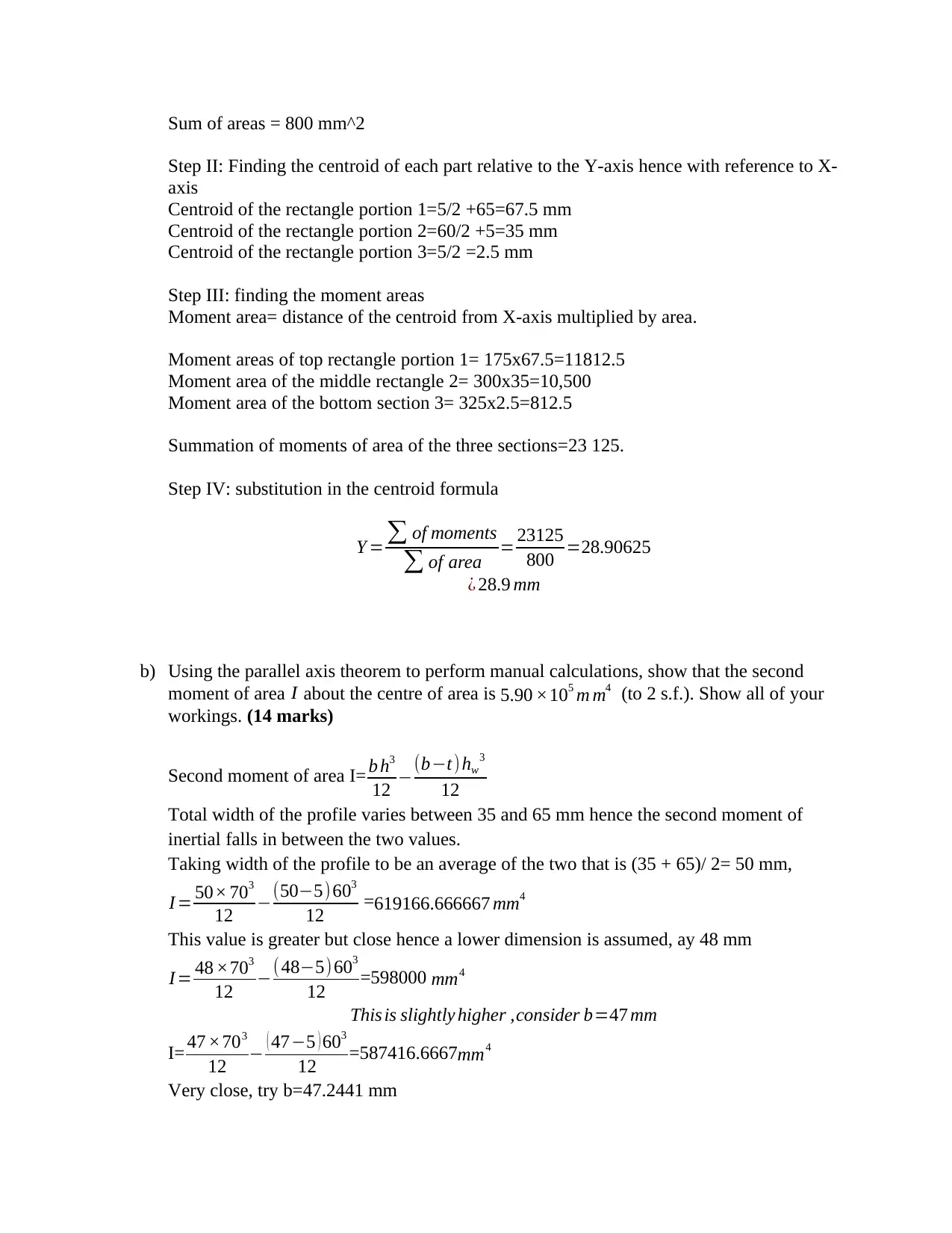
Sum of areas = 800 mm^2
Step II: Finding the centroid of each part relative to the Y-axis hence with reference to X-
axis
Centroid of the rectangle portion 1=5/2 +65=67.5 mm
Centroid of the rectangle portion 2=60/2 +5=35 mm
Centroid of the rectangle portion 3=5/2 =2.5 mm
Step III: finding the moment areas
Moment area= distance of the centroid from X-axis multiplied by area.
Moment areas of top rectangle portion 1= 175x67.5=11812.5
Moment area of the middle rectangle 2= 300x35=10,500
Moment area of the bottom section 3= 325x2.5=812.5
Summation of moments of area of the three sections=23 125.
Step IV: substitution in the centroid formula
Y = ∑ of moments
∑ of area = 23125
800 =28.90625
¿ 28.9 mm
b) Using the parallel axis theorem to perform manual calculations, show that the second
moment of area I about the centre of area is 5.90 ×10⁵ m m4 (to 2 s.f.). Show all of your
workings. (14 marks)
Second moment of area I= b h3
12 −(b−t) hw
3
12
Total width of the profile varies between 35 and 65 mm hence the second moment of
inertial falls in between the two values.
Taking width of the profile to be an average of the two that is (35 + 65)/ 2= 50 mm,
I = 50× 703
12 −(50−5) 603
12 =619166.666667 mm4
This value is greater but close hence a lower dimension is assumed, ay 48 mm
I = 48 ×703
12 −(48−5)603
12 =598000 mm4
This is slightly higher ,consider b=47 mm
I= 47 ×703
12 − ( 47−5 ) 603
12 =587416.6667mm4
Very close, try b=47.2441 mm
Paraphrase This Document
Need a fresh take? Get an instant paraphrase of this document with our AI Paraphraser
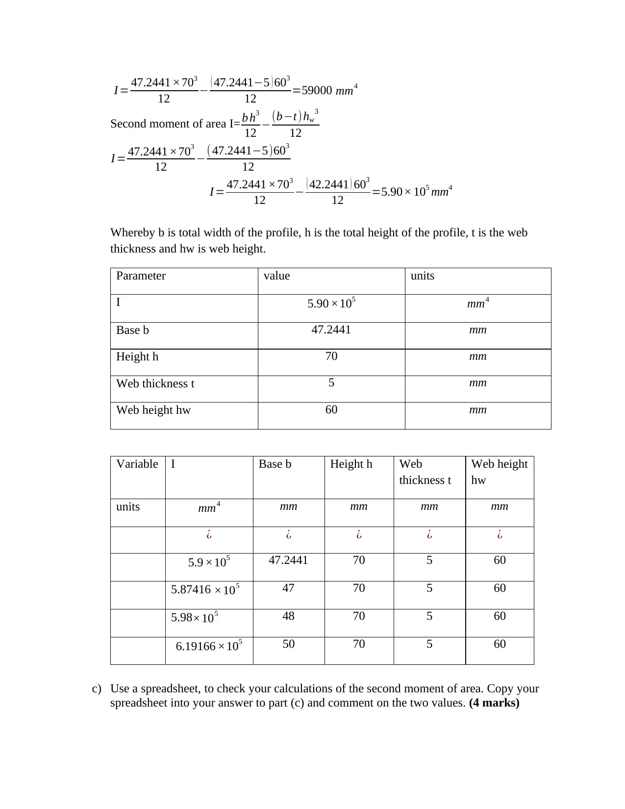
I = 47.2441 ×703
12 − ( 47.2441−5 ) 603
12 =59000 mm4
Second moment of area I= b h3
12 −(b−t) hw
3
12
I = 47.2441 ×703
12 −( 47.2441−5)603
12
I = 47.2441 ×703
12 − ( 42.2441 ) 603
12 =5.90× 105 mm4
Whereby b is total width of the profile, h is the total height of the profile, t is the web
thickness and hw is web height.
Parameter value units
I 5.90 ×105 mm4
Base b 47.2441 mm
Height h 70 mm
Web thickness t 5 mm
Web height hw 60 mm
Variable I Base b Height h Web
thickness t
Web height
hw
units mm4 mm mm mm mm
¿ ¿ ¿ ¿ ¿
5.9 ×10⁵ 47.2441 70 5 60
5.87416 ×10⁵ 47 70 5 60
5.98×10⁵ 48 70 5 60
6.19166 ×10⁵ 50 70 5 60
c) Use a spreadsheet, to check your calculations of the second moment of area. Copy your
spreadsheet into your answer to part (c) and comment on the two values. (4 marks)
Variab
le
I Bas
e b
Heig
ht h
Web
thickne
ss t
Web
heig
ht
hw
units mm4 mm mm mm mm
¿ ¿ ¿ ¿ ¿
5.9 ×10⁵ 47.2441 70 5 60
6.19166 ×10⁵
50 70 5 60
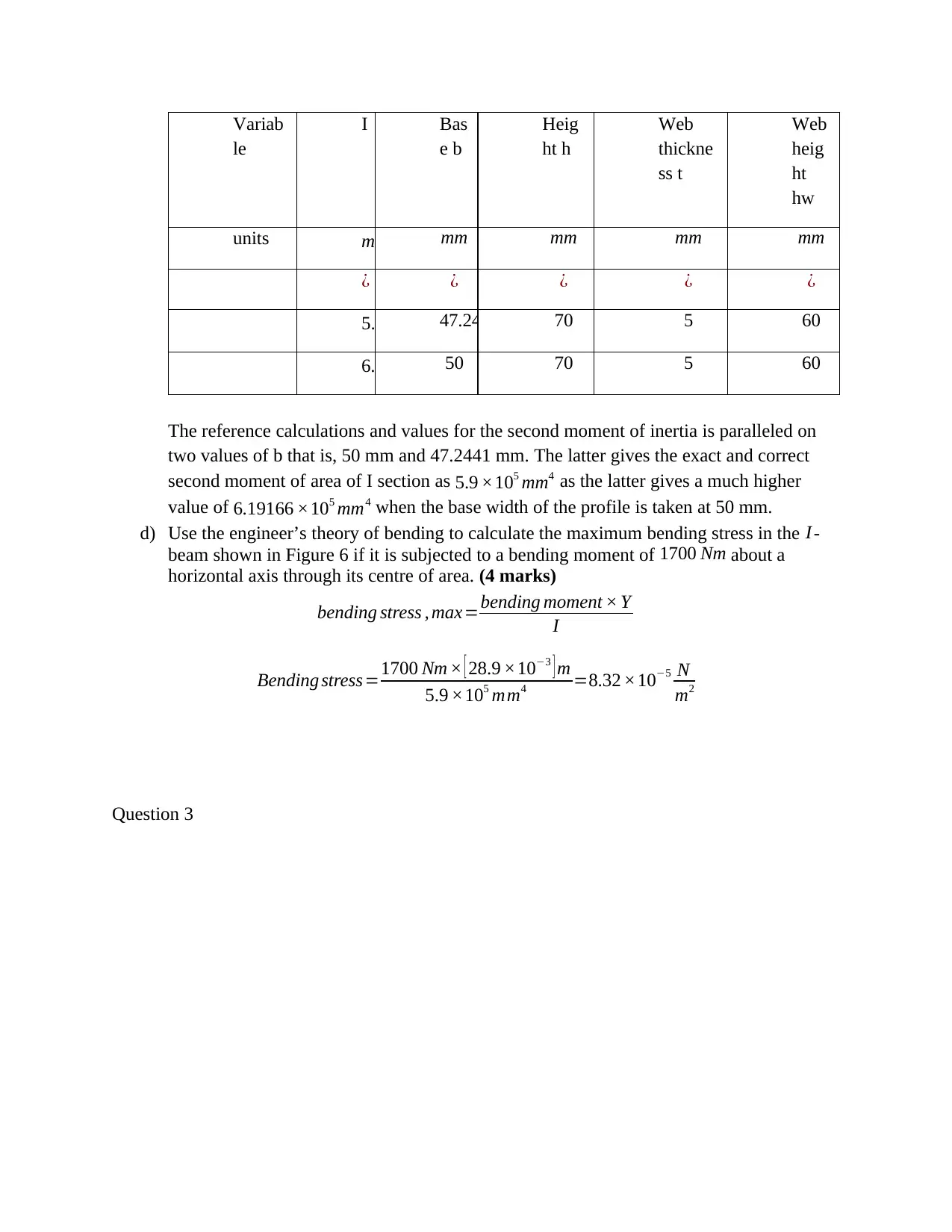
The reference calculations and values for the second moment of inertia is paralleled on
two values of b that is, 50 mm and 47.2441 mm. The latter gives the exact and correct
second moment of area of I section as 5.9 ×105 mm4 as the latter gives a much higher
value of 6.19166 ×105 mm4 when the base width of the profile is taken at 50 mm.
d) Use the engineer’s theory of bending to calculate the maximum bending stress in the I-
beam shown in Figure 6 if it is subjected to a bending moment of 1700 Nm about a
horizontal axis through its centre of area. (4 marks)
bending stress , max=bending moment × Y
I
Bending stress=1700 Nm × [ 28.9 ×10⁻³ ] m
5.9 ×105 mm4 =8.32 ×10⁻⁵ N
m2
Question 3
le
I Bas
e b
Heig
ht h
Web
thickne
ss t
Web
heig
ht
hw
units mm4 mm mm mm mm
¿ ¿ ¿ ¿ ¿
5.9 ×10⁵ 47.2441 70 5 60
6.19166 ×10⁵
50 70 5 60
The reference calculations and values for the second moment of inertia is paralleled on
two values of b that is, 50 mm and 47.2441 mm. The latter gives the exact and correct
second moment of area of I section as 5.9 ×105 mm4 as the latter gives a much higher
value of 6.19166 ×105 mm4 when the base width of the profile is taken at 50 mm.
d) Use the engineer’s theory of bending to calculate the maximum bending stress in the I-
beam shown in Figure 6 if it is subjected to a bending moment of 1700 Nm about a
horizontal axis through its centre of area. (4 marks)
bending stress , max=bending moment × Y
I
Bending stress=1700 Nm × [ 28.9 ×10⁻³ ] m
5.9 ×105 mm4 =8.32 ×10⁻⁵ N
m2
Question 3
⊘ This is a preview!⊘
Do you want full access?
Subscribe today to unlock all pages.
Trusted by 1+ million students worldwide
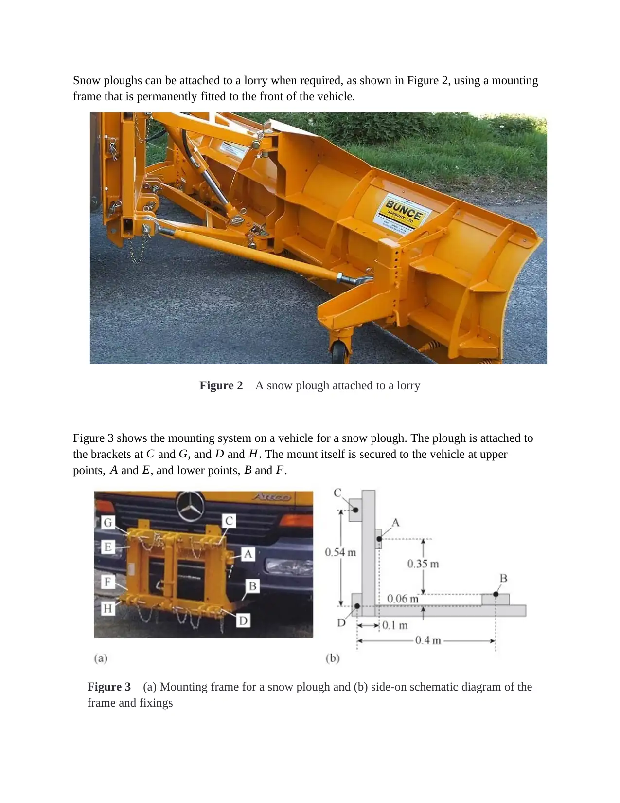
Snow ploughs can be attached to a lorry when required, as shown in Figure 2, using a mounting
frame that is permanently fitted to the front of the vehicle.
Figure 2 A snow plough attached to a lorry
Figure 3 shows the mounting system on a vehicle for a snow plough. The plough is attached to
the brackets at C and G, and D and H. The mount itself is secured to the vehicle at upper
points, A and E, and lower points, B and F.
Figure 3 (a) Mounting frame for a snow plough and (b) side-on schematic diagram of the
frame and fixings
Paraphrase This Document
Need a fresh take? Get an instant paraphrase of this document with our AI Paraphraser
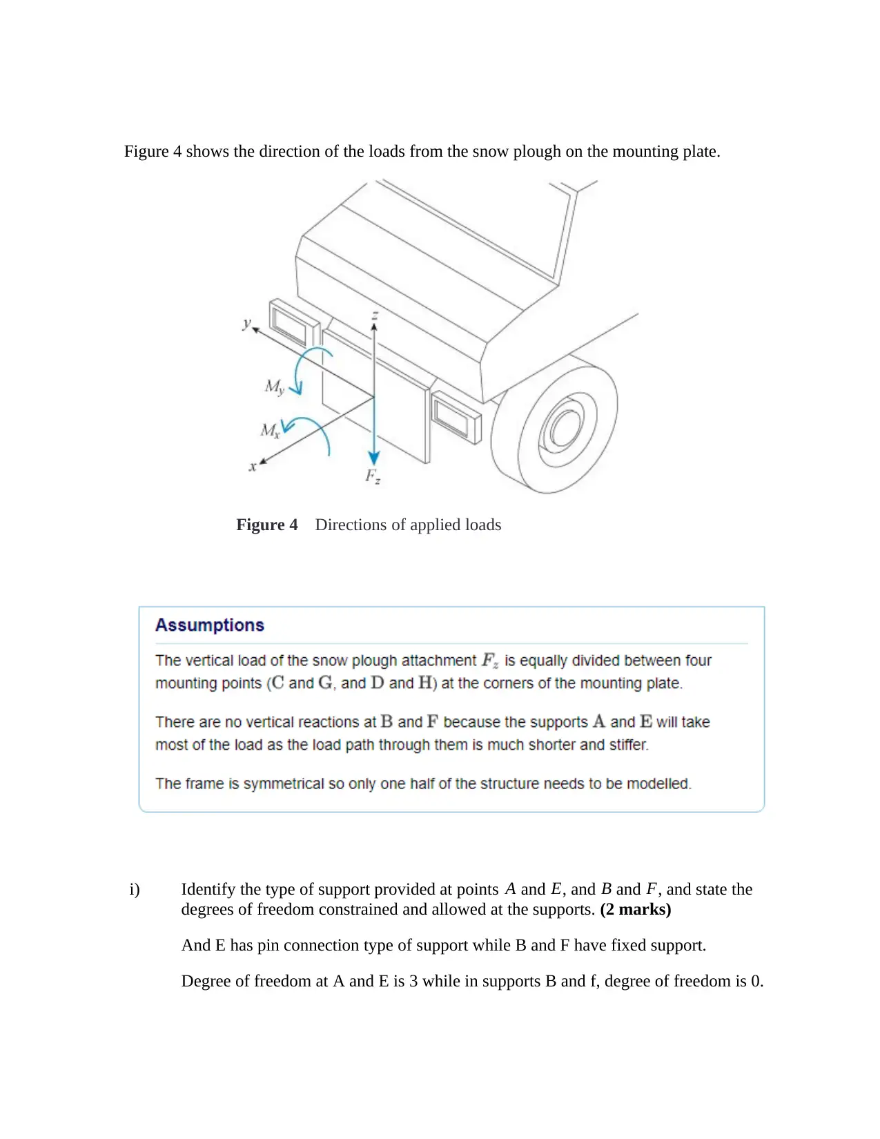
Figure 4 shows the direction of the loads from the snow plough on the mounting plate.
Figure 4 Directions of applied loads
i) Identify the type of support provided at points A and E, and B and F, and state the
degrees of freedom constrained and allowed at the supports. (2 marks)
And E has pin connection type of support while B and F have fixed support.
Degree of freedom at A and E is 3 while in supports B and f, degree of freedom is 0.
ii) Describe the load path taken by the weight of the snow plough attachment Fz through
the mounting system. (3 marks)
The load through Fz I distributed through C and D equally from which the load is
distributed to point A. on the other side of the plough, load is equally transmitted though
G and H which eventually distributes the load to point E.
For the remainder of this question assume that the only load applied to the snow
plough frame is FZ therefore the moments M x or M y are zero.
iii) Show that the applied force at each of the four support points C andG, and D and H,
is 5.5 kN downward when the download load Fz is applied to the snow plough
attachment. (2 marks)
Total load Fz derived as 22 KN and is equally distributed to points C, F, D and H. since this load
is equally shared between these supports, applied force at each of the 4 supports =
22 ÷ 4=5.5 KN
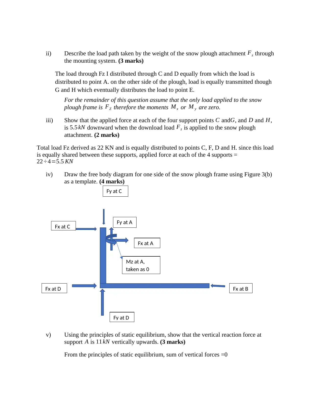
iv) Draw the free body diagram for one side of the snow plough frame using Figure 3(b)
as a template. (4 marks)
v) Using the principles of static equilibrium, show that the vertical reaction force at
support A is 11 kN vertically upwards. (3 marks)
From the principles of static equilibrium, sum of vertical forces =0
Fy at C
Fx at C
Fx at A
Fy at A
Mz at A,
taken as 0
Fx at D
Fy at D
Fx at B
the mounting system. (3 marks)
The load through Fz I distributed through C and D equally from which the load is
distributed to point A. on the other side of the plough, load is equally transmitted though
G and H which eventually distributes the load to point E.
For the remainder of this question assume that the only load applied to the snow
plough frame is FZ therefore the moments M x or M y are zero.
iii) Show that the applied force at each of the four support points C andG, and D and H,
is 5.5 kN downward when the download load Fz is applied to the snow plough
attachment. (2 marks)
Total load Fz derived as 22 KN and is equally distributed to points C, F, D and H. since this load
is equally shared between these supports, applied force at each of the 4 supports =
22 ÷ 4=5.5 KN
iv) Draw the free body diagram for one side of the snow plough frame using Figure 3(b)
as a template. (4 marks)
v) Using the principles of static equilibrium, show that the vertical reaction force at
support A is 11 kN vertically upwards. (3 marks)
From the principles of static equilibrium, sum of vertical forces =0
Fy at C
Fx at C
Fx at A
Fy at A
Mz at A,
taken as 0
Fx at D
Fy at D
Fx at B
⊘ This is a preview!⊘
Do you want full access?
Subscribe today to unlock all pages.
Trusted by 1+ million students worldwide
Vertical force at support E + vertical force at support A= 22 KN, this load is shared
equally between the two supports based on symmetry. Therefore, reactions at A=
reaction at E= 22
2 =11kN upwards.
vi) Again, using the principle of static equilibrium, calculate the horizontal reaction
forces at the support points A and B. Give your answers to two significant
figures. (6 marks)
Taking moments about A, fcx0.19= fbx0.35 where fc and fb are reactions at supports C and B
respectively.
5.5 ×0.19=fb ×0.35 ,
Reaction at b,fb=5.5 × 0.19
0.35 =2.99 kN
Again, taking momenta about D, -fc x0.54+ fa x 0.35=fb x 0.4,
-5.5 ×0.54 +0.35 fa=2.99 × 0.4
−2.97+0.35 fa=1.196 ,
Reaction at A , fa=1.196+2.97=4.166 kN =4.17kN (¿ 2 s . f )
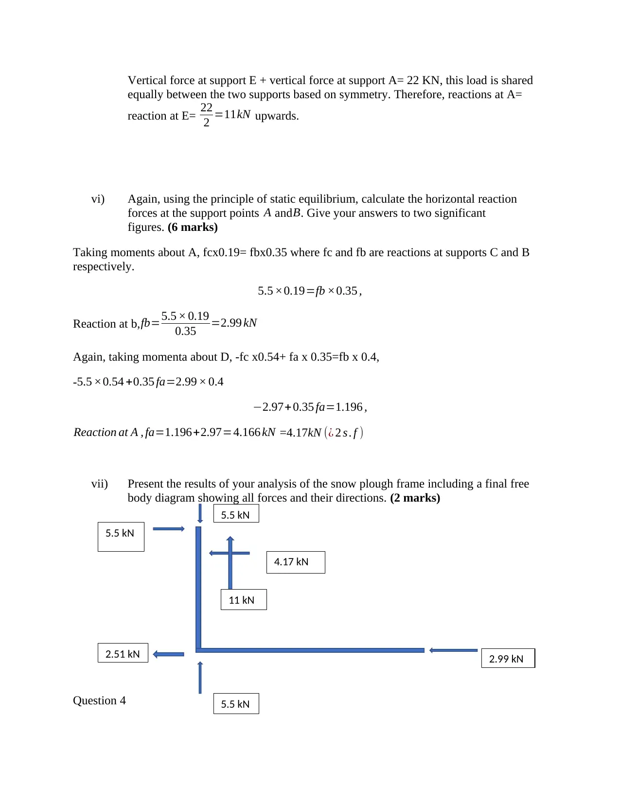
vii) Present the results of your analysis of the snow plough frame including a final free
body diagram showing all forces and their directions. (2 marks)
Question 4
5.5 kN
5.5 kN
4.17 kN
11 kN
2.51 kN
5.5 kN
2.99 kN
equally between the two supports based on symmetry. Therefore, reactions at A=
reaction at E= 22
2 =11kN upwards.
vi) Again, using the principle of static equilibrium, calculate the horizontal reaction
forces at the support points A and B. Give your answers to two significant
figures. (6 marks)
Taking moments about A, fcx0.19= fbx0.35 where fc and fb are reactions at supports C and B
respectively.
5.5 ×0.19=fb ×0.35 ,
Reaction at b,fb=5.5 × 0.19
0.35 =2.99 kN
Again, taking momenta about D, -fc x0.54+ fa x 0.35=fb x 0.4,
-5.5 ×0.54 +0.35 fa=2.99 × 0.4
−2.97+0.35 fa=1.196 ,
Reaction at A , fa=1.196+2.97=4.166 kN =4.17kN (¿ 2 s . f )
vii) Present the results of your analysis of the snow plough frame including a final free
body diagram showing all forces and their directions. (2 marks)
Question 4
5.5 kN
5.5 kN
4.17 kN
11 kN
2.51 kN
5.5 kN
2.99 kN
Paraphrase This Document
Need a fresh take? Get an instant paraphrase of this document with our AI Paraphraser
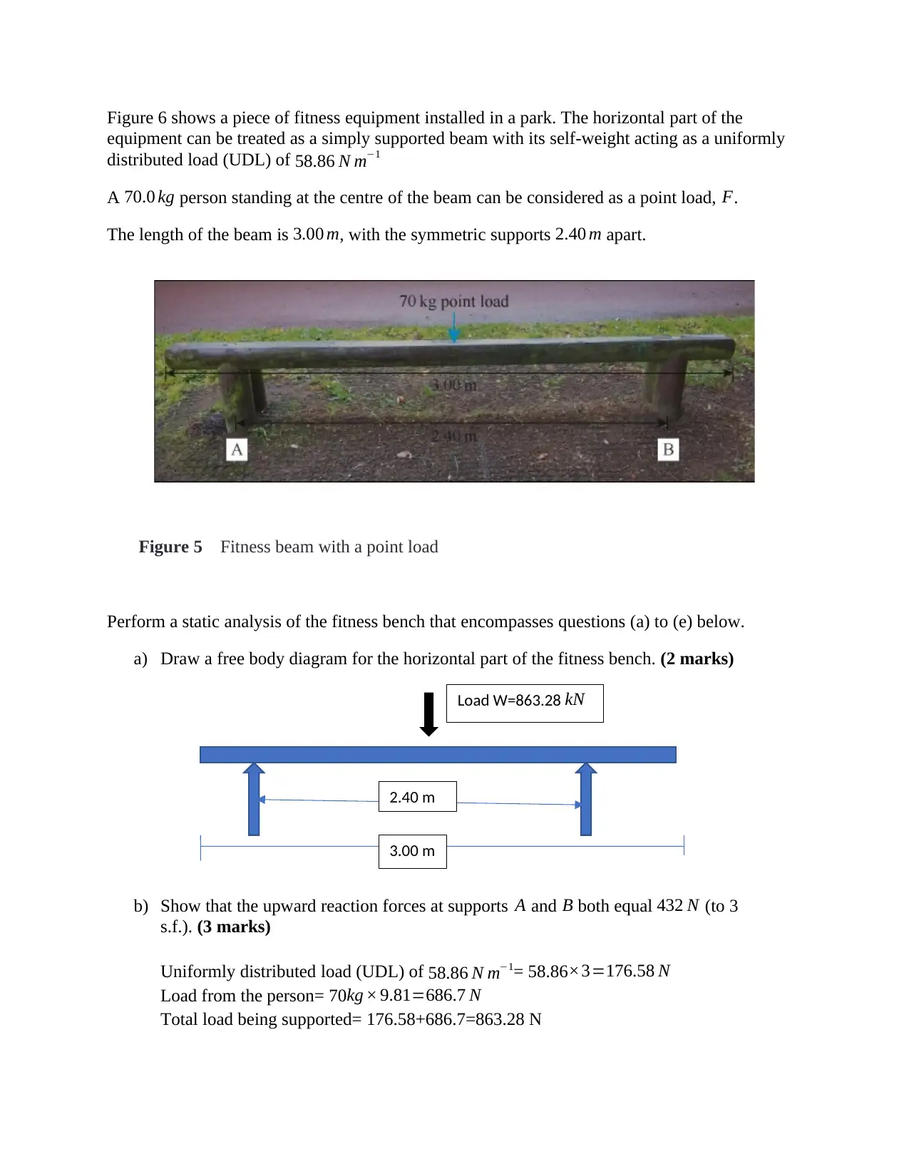
Figure 6 shows a piece of fitness equipment installed in a park. The horizontal part of the
equipment can be treated as a simply supported beam with its self-weight acting as a uniformly
distributed load (UDL) of 58.86 N m−1
A 70.0 kg person standing at the centre of the beam can be considered as a point load, F.
The length of the beam is 3.00 m, with the symmetric supports 2.40 m apart.
Figure 5 Fitness beam with a point load
Perform a static analysis of the fitness bench that encompasses questions (a) to (e) below.
a) Draw a free body diagram for the horizontal part of the fitness bench. (2 marks)
b) Show that the upward reaction forces at supports A and B both equal 432 N (to 3
s.f.). (3 marks)
Uniformly distributed load (UDL) of 58.86 N m−1= 58.86×3=176.58 N
Load from the person= 70kg × 9.81=686.7 N
Total load being supported= 176.58+686.7=863.28 N
2.40 m
3.00 m
Load W=863.28 kN
This load is supported equally between the two supports. Therefore, upward reaction at
A= reaction at B= 863.28
2 =431.64 N =432 N
c) In preparation for drawing the SF and BM diagrams for the fitness bench, you now need
to perform calculations to allow you to draw the diagrams correctly. Quantify all relevant
forces and moments and include all of your workings in your answer. Give your answers
to three significant figures. (12 marks)
Reactions at A= reaction at B= 431.64 KN
Maximum positive shear = W (l−x )
l =863.28 ( 3−1.2 )
3 =¿517.97 kN
Maximum negative shear= −W ( l−x )
l = 863.28 ( 3−1.2 )
3 =−517.97 kN
Maximum bending moment, just like shear occurs when the load is at the section itself.
Maximum moment therefore, =W x x ( l−x )
l =863.28 × 1.2 (3.0−1.2 )
3.0 =621.56 kNm
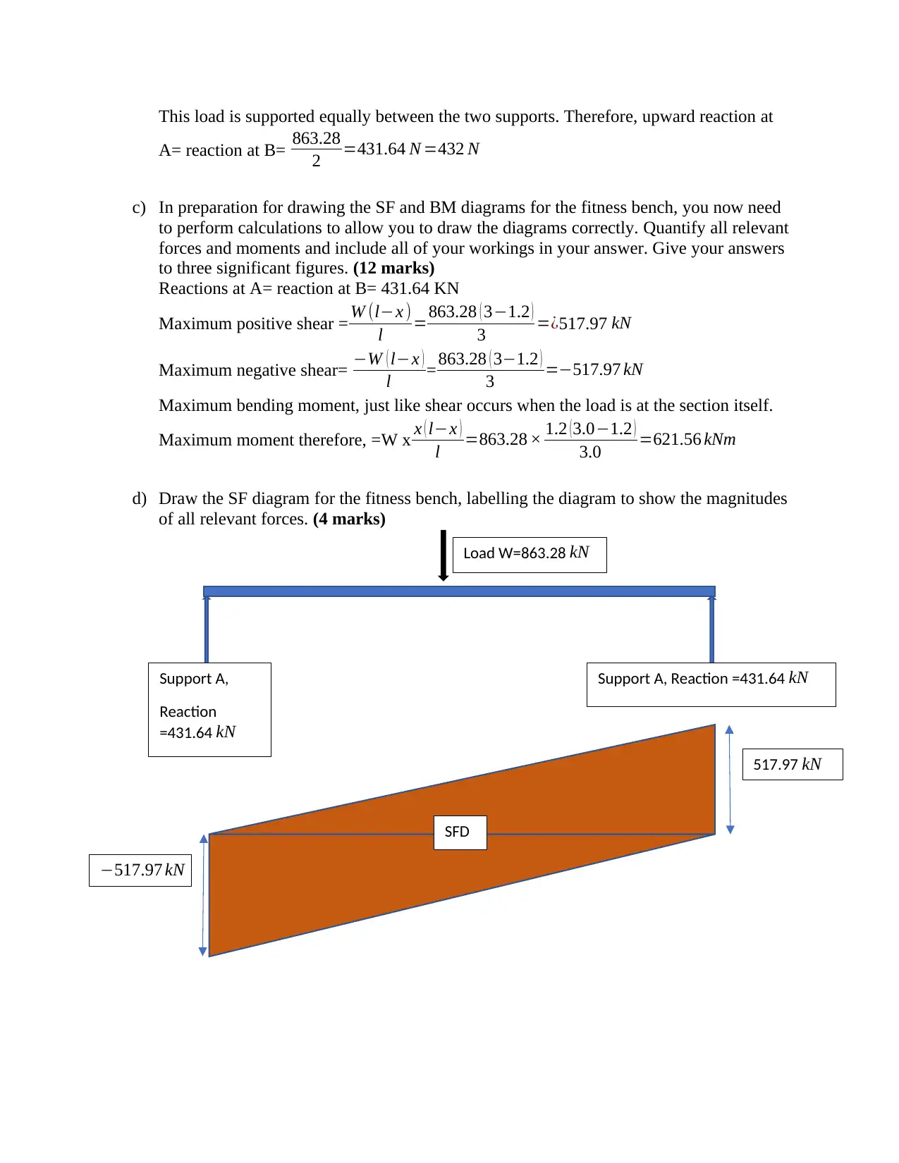
d) Draw the SF diagram for the fitness bench, labelling the diagram to show the magnitudes
of all relevant forces. (4 marks)
517.97 kN
−517.97 kN
Load W=863.28 kN
Support A,
Reaction
=431.64 kN
Support A, Reaction =431.64 kN
SFD
A= reaction at B= 863.28
2 =431.64 N =432 N
c) In preparation for drawing the SF and BM diagrams for the fitness bench, you now need
to perform calculations to allow you to draw the diagrams correctly. Quantify all relevant
forces and moments and include all of your workings in your answer. Give your answers
to three significant figures. (12 marks)
Reactions at A= reaction at B= 431.64 KN
Maximum positive shear = W (l−x )
l =863.28 ( 3−1.2 )
3 =¿517.97 kN
Maximum negative shear= −W ( l−x )
l = 863.28 ( 3−1.2 )
3 =−517.97 kN
Maximum bending moment, just like shear occurs when the load is at the section itself.
Maximum moment therefore, =W x x ( l−x )
l =863.28 × 1.2 (3.0−1.2 )
3.0 =621.56 kNm
d) Draw the SF diagram for the fitness bench, labelling the diagram to show the magnitudes
of all relevant forces. (4 marks)
517.97 kN
−517.97 kN
Load W=863.28 kN
Support A,
Reaction
=431.64 kN
Support A, Reaction =431.64 kN
SFD
⊘ This is a preview!⊘
Do you want full access?
Subscribe today to unlock all pages.
Trusted by 1+ million students worldwide
1 out of 13
Your All-in-One AI-Powered Toolkit for Academic Success.
+13062052269
info@desklib.com
Available 24*7 on WhatsApp / Email
![[object Object]](/_next/static/media/star-bottom.7253800d.svg)
Unlock your academic potential
Copyright © 2020–2026 A2Z Services. All Rights Reserved. Developed and managed by ZUCOL.