Structural Analysis and Design Report: Cantilevers, Frames, Columns
VerifiedAdded on 2020/03/01
|36
|6325
|98
Report
AI Summary
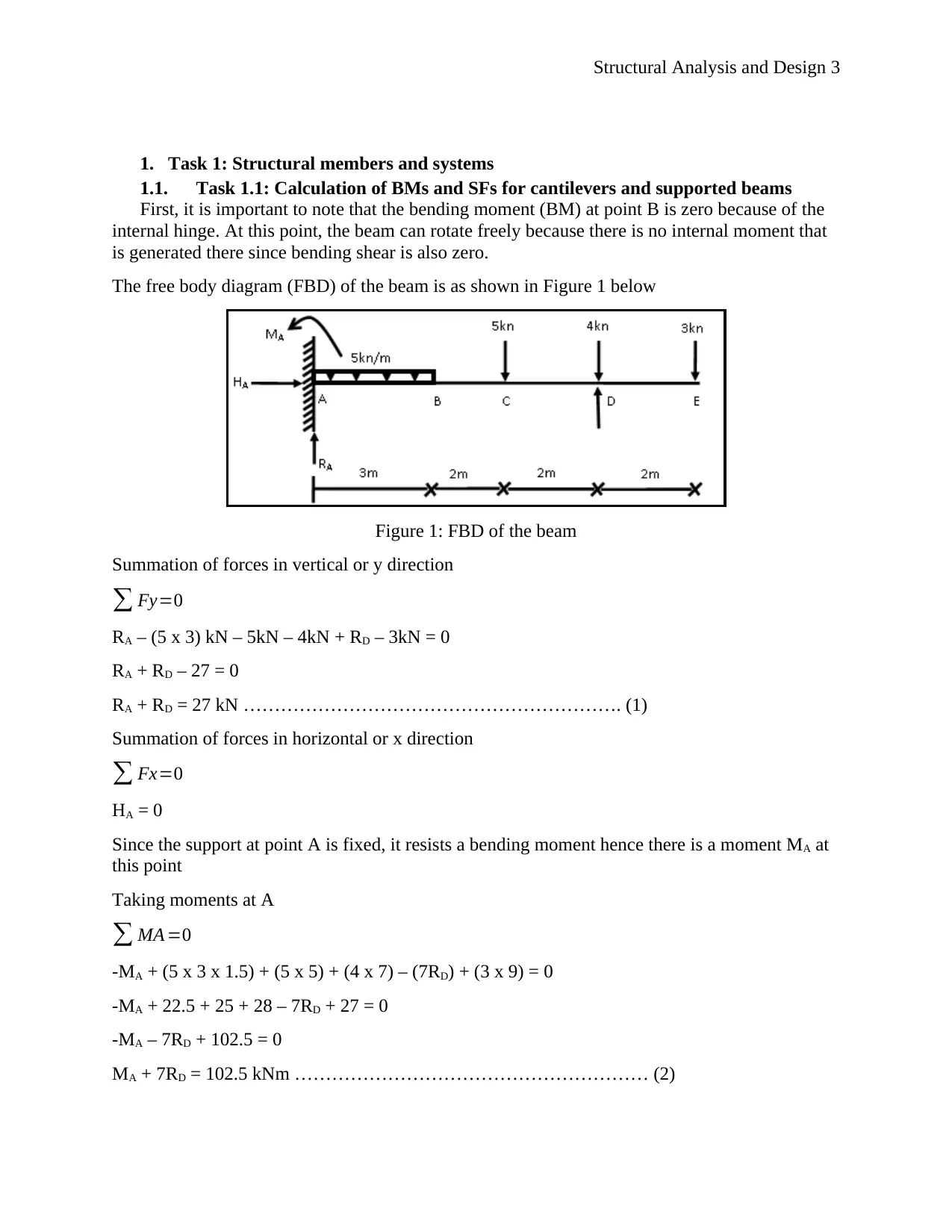
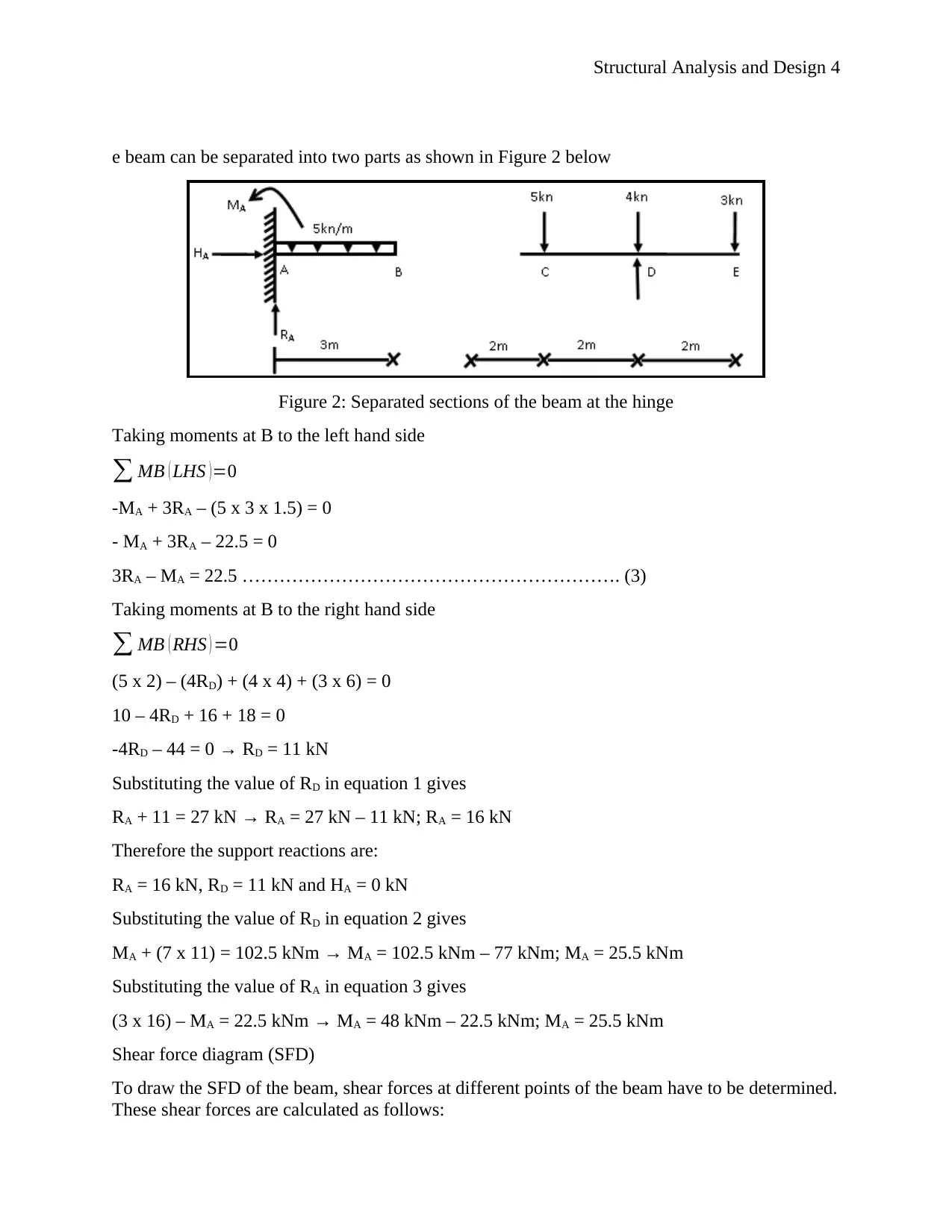
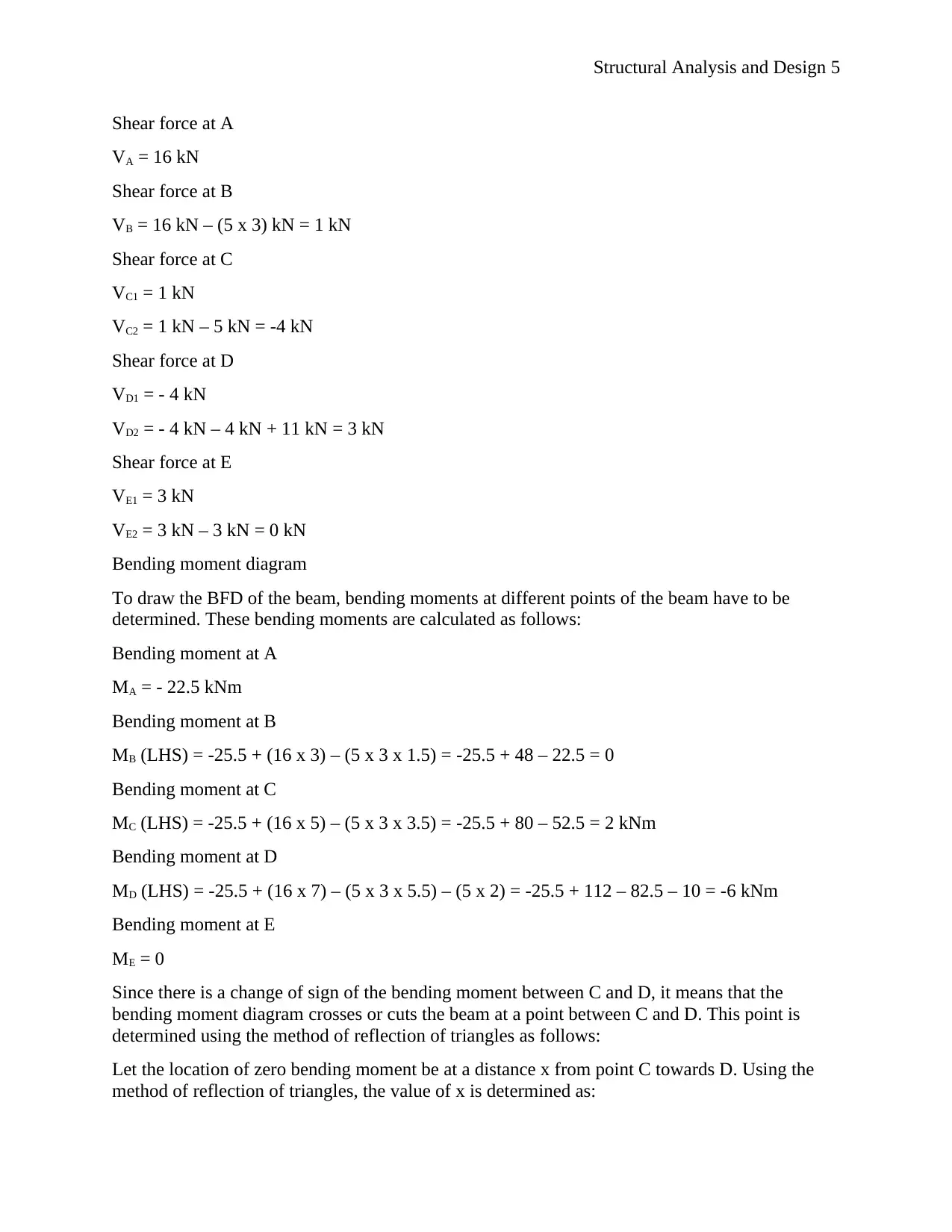
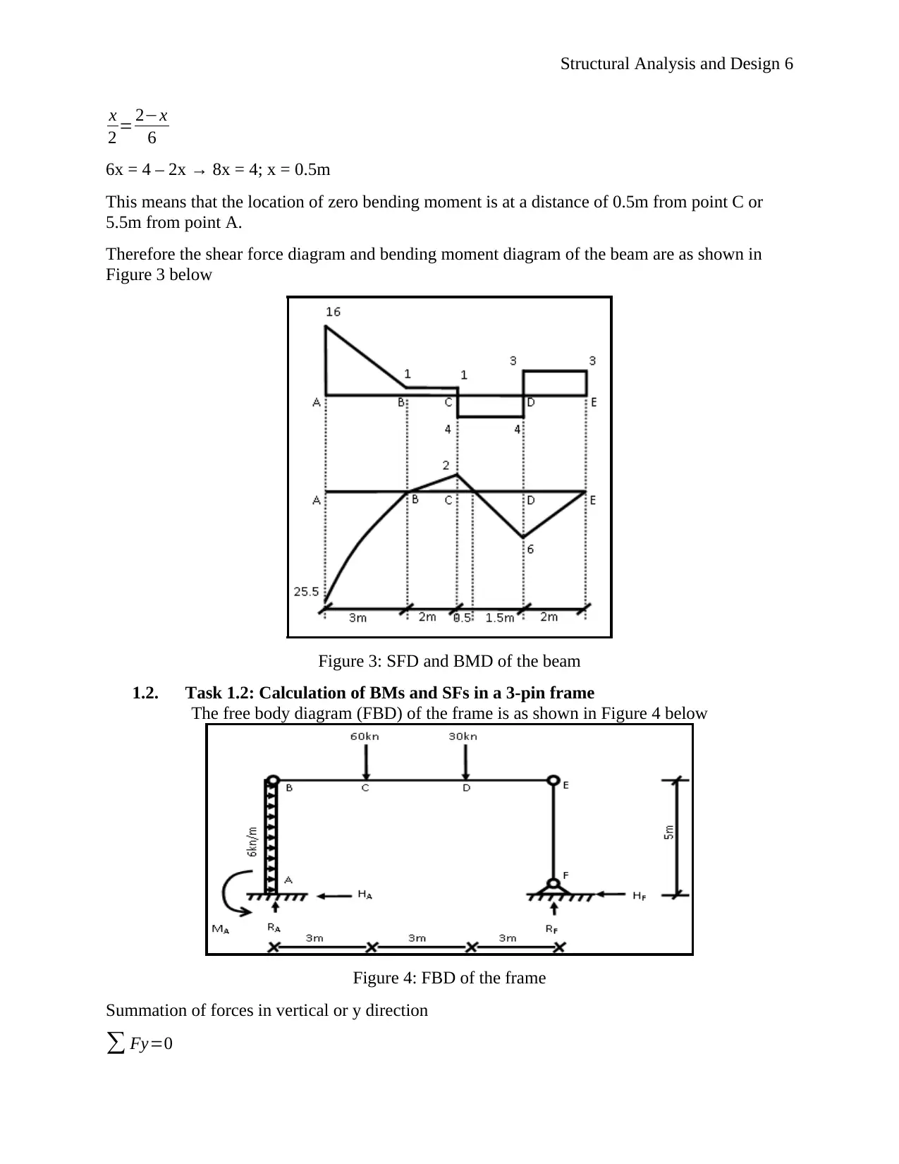
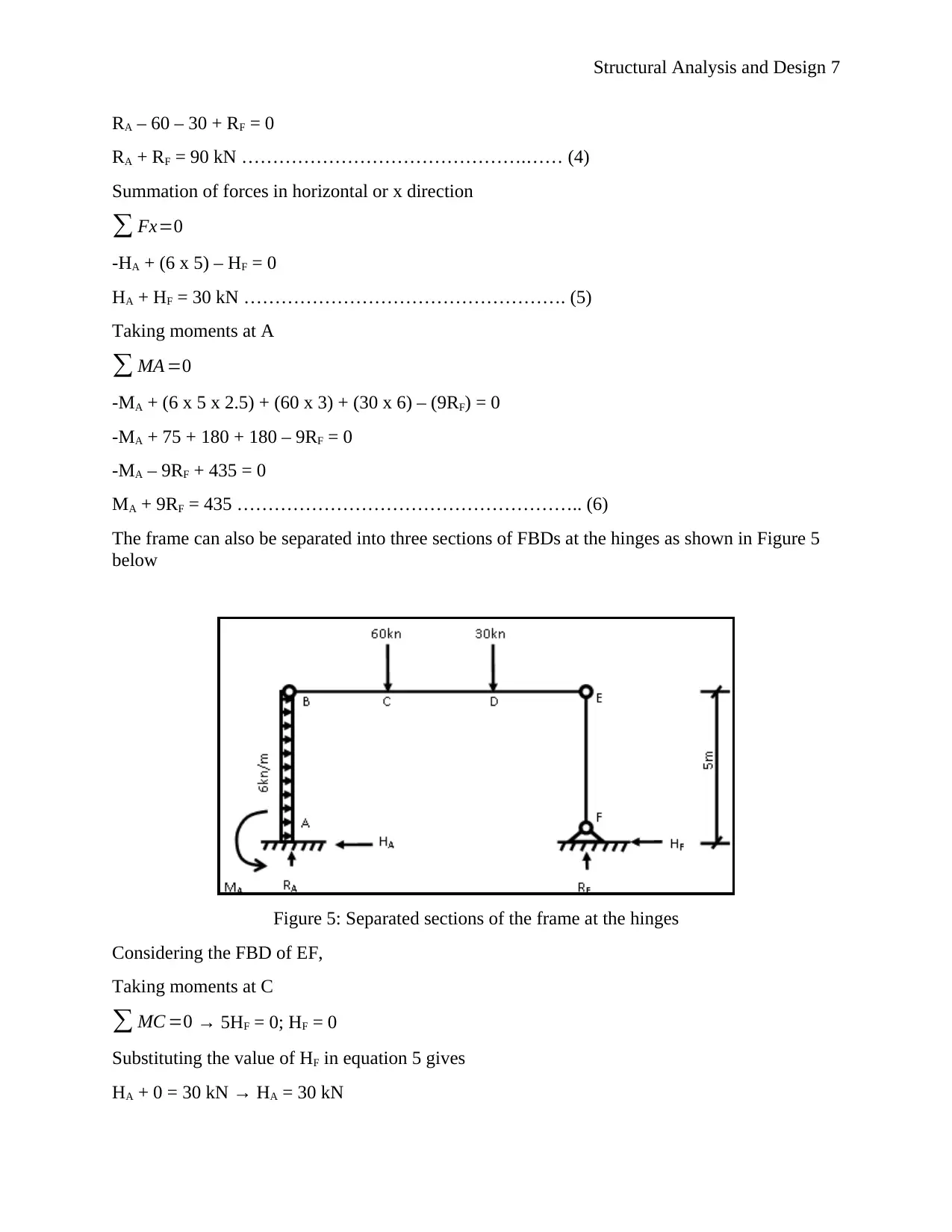
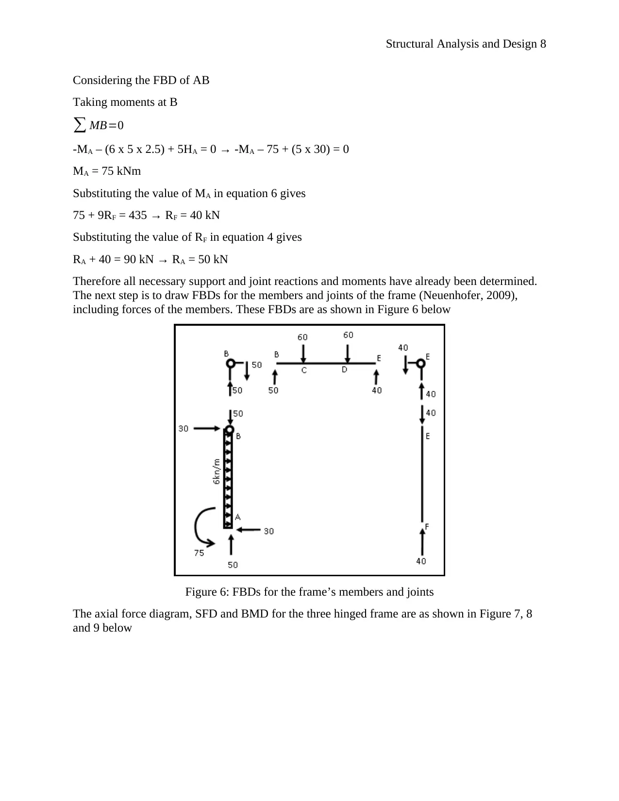
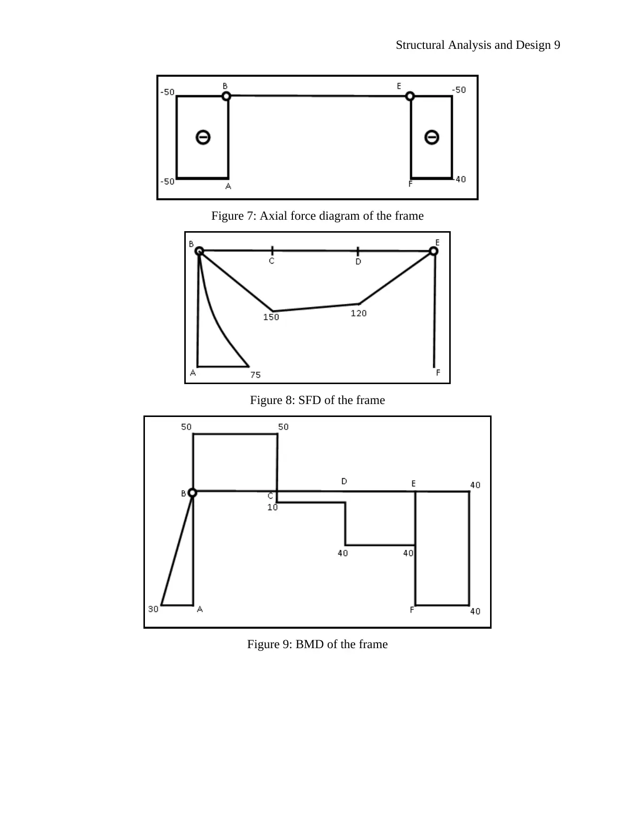
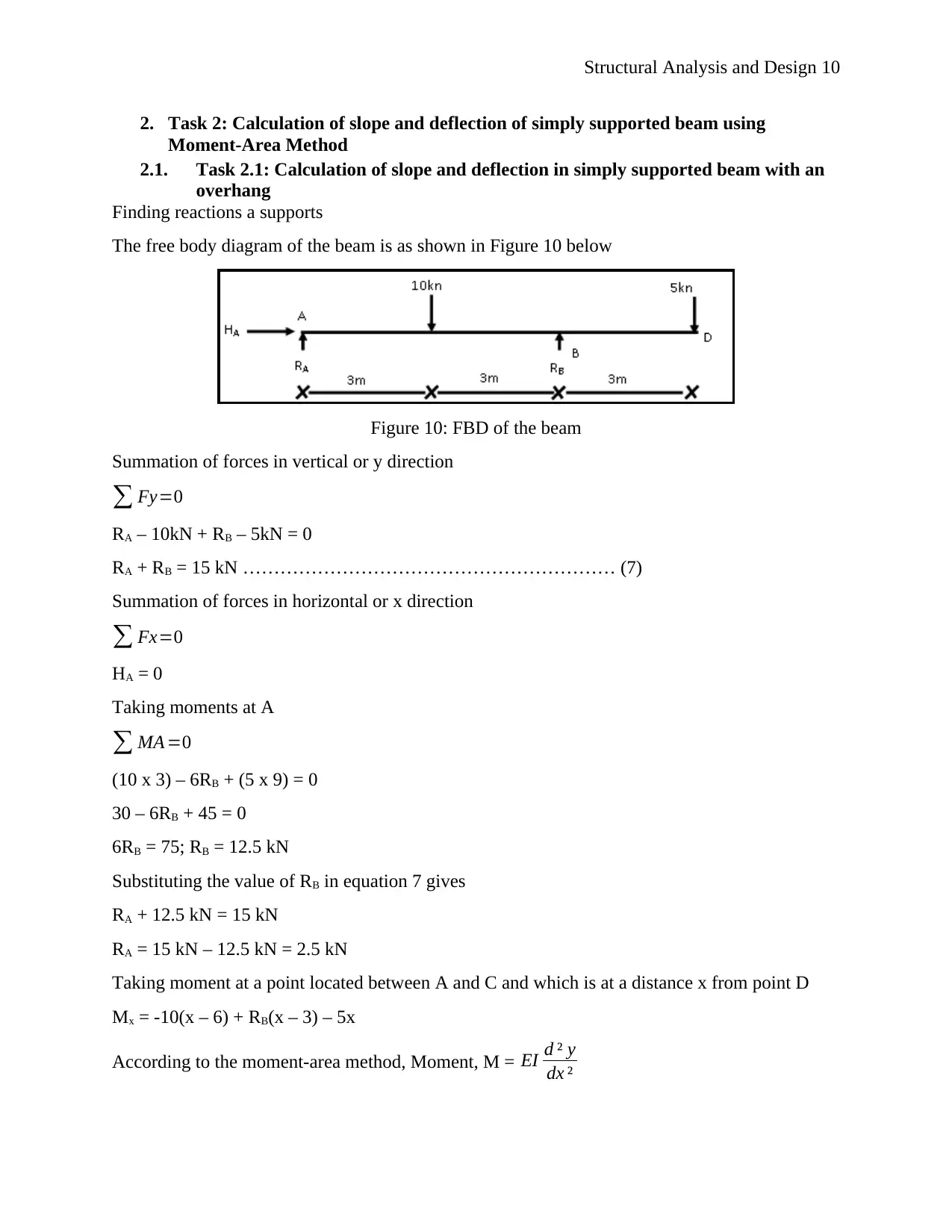
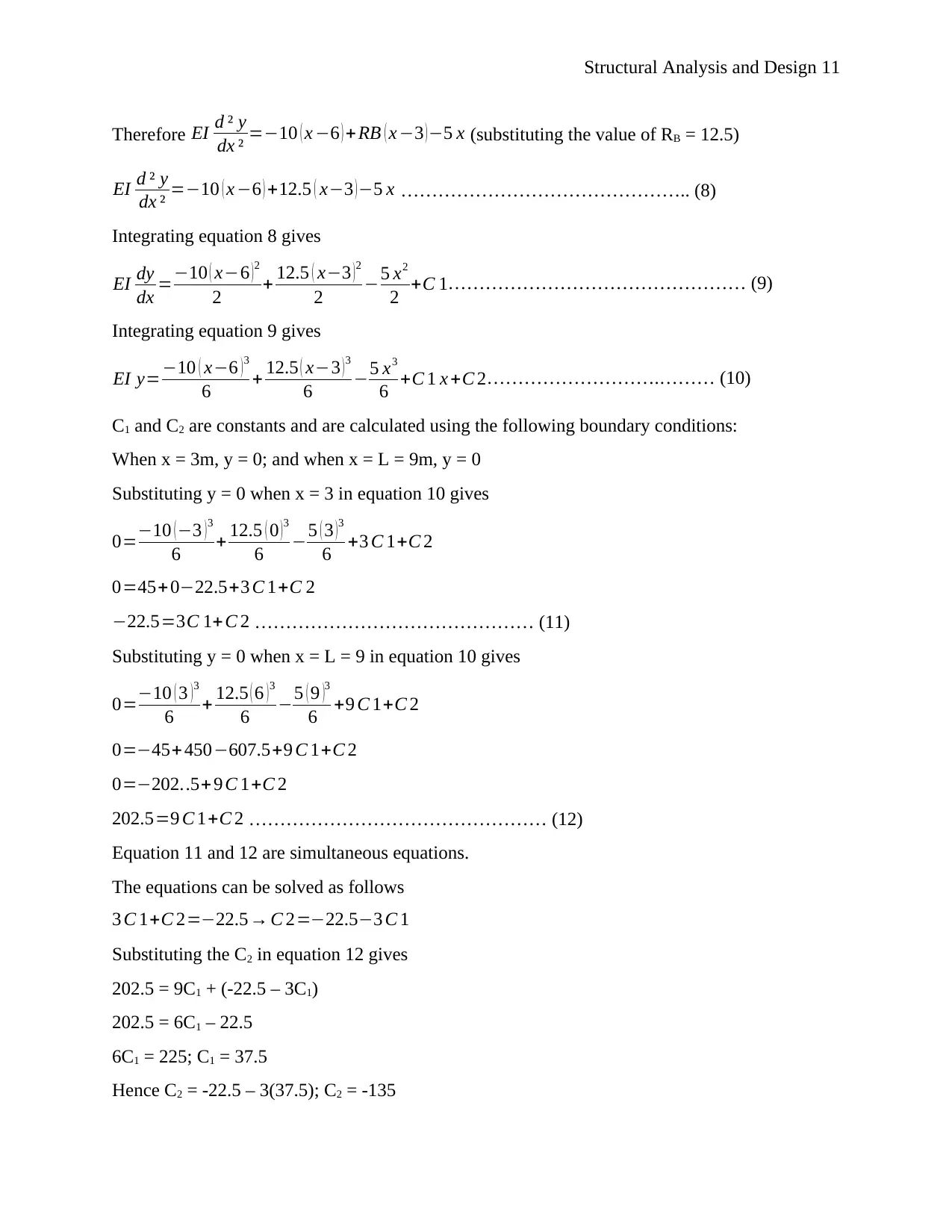
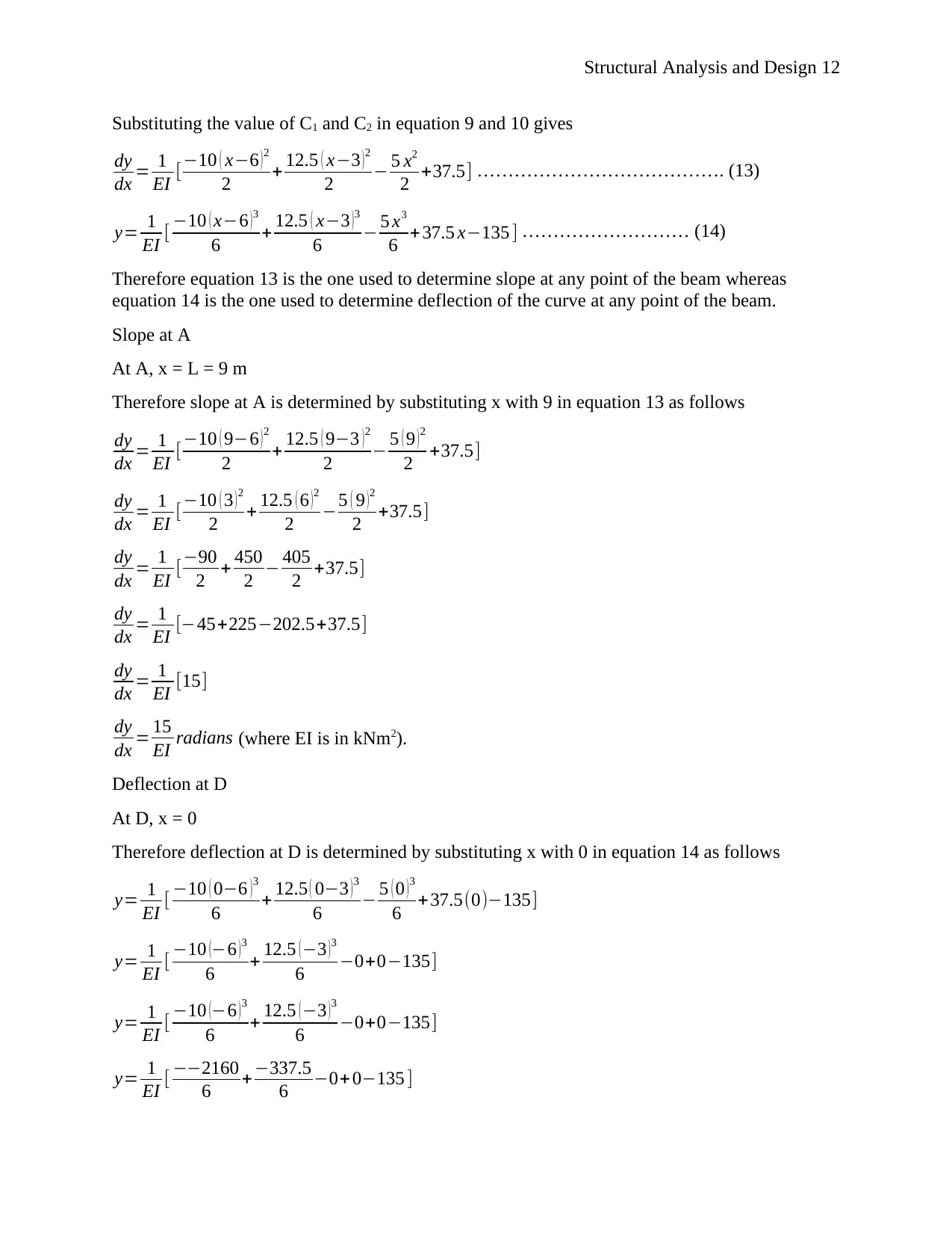
This report presents a comprehensive structural analysis and design, covering various structural elements and systems. It begins with the calculation of bending moments (BMs) and shear forces (SFs) for cantilevers and supported beams, followed by an analysis of a 3-pin frame. The report then explores the calculation of slope and deflection of a simply supported beam using the Moment-Area Method, including a discussion of its assumptions and limitations. Finally, it addresses the determination of maximum and minimum stresses and eccentricity in short columns, detailing the axial load carrying capacity of perfectly elastic columns. The report includes detailed calculations, diagrams, and explanations, making it a valuable resource for civil engineering students. The assignment is a contribution by a student to be published on the website Desklib.

Structural Analysis and Design 1
STRUCTURAL ANALYSIS AND DESIGN
Name
Course
Professor
University
City/state
Date
STRUCTURAL ANALYSIS AND DESIGN
Name
Course
Professor
University
City/state
Date
Paraphrase This Document
Need a fresh take? Get an instant paraphrase of this document with our AI Paraphraser

Structural Analysis and Design 2
Contents
1. Task 1: Structural members and systems........................................................................................3
1.1. Task 1.1: Calculation of BMs and SFs for cantilevers and supported beams.......................3
1.2. Task 1.2: Calculation of BMs and SFs in a 3-pin frame.........................................................6
2. Task 2: Calculation of slope and deflection of simply supported beam using Moment-Area
Method.....................................................................................................................................................10
2.1. Task 2.1: Calculation of slope and deflection in simply supported beam with an overhang
10
Assumptions and limitations of area-moment method........................................................................12
3. Task 3: Maximum and minimum stresses and eccentricity of short columns.............................13
3.1. Task 3.1: Determining axial load carrying capacity of perfectly elastic columns...............13
a) Maximum and minimum stresses...............................................................................................13
b) Maximum eccentricity................................................................................................................14
References................................................................................................................................................35

Structural Analysis and Design 3
1. Task 1: Structural members and systems
1.1. Task 1.1: Calculation of BMs and SFs for cantilevers and supported beams
First, it is important to note that the bending moment (BM) at point B is zero because of the
internal hinge. At this point, the beam can rotate freely because there is no internal moment that
is generated there since bending shear is also zero.
The free body diagram (FBD) of the beam is as shown in Figure 1 below
Figure 1: FBD of the beam
Summation of forces in vertical or y direction
∑ Fy=0
RA – (5 x 3) kN – 5kN – 4kN + RD – 3kN = 0
RA + RD – 27 = 0
RA + RD = 27 kN ……………………………………………………. (1)
Summation of forces in horizontal or x direction
∑ Fx=0
HA = 0
Since the support at point A is fixed, it resists a bending moment hence there is a moment MA at
this point
Taking moments at A
∑ MA =0
-MA + (5 x 3 x 1.5) + (5 x 5) + (4 x 7) – (7RD) + (3 x 9) = 0
-MA + 22.5 + 25 + 28 – 7RD + 27 = 0
-MA – 7RD + 102.5 = 0
MA + 7RD = 102.5 kNm ………………………………………………… (2)
⊘ This is a preview!⊘
Do you want full access?
Subscribe today to unlock all pages.

Trusted by 1+ million students worldwide

Structural Analysis and Design 4
e beam can be separated into two parts as shown in Figure 2 below
Figure 2: Separated sections of the beam at the hinge
Taking moments at B to the left hand side
∑ MB ( LHS ) =0
-MA + 3RA – (5 x 3 x 1.5) = 0
- MA + 3RA – 22.5 = 0
3RA – MA = 22.5 ……………………………………………………. (3)
Taking moments at B to the right hand side
∑ MB ( RHS ) =0
(5 x 2) – (4RD) + (4 x 4) + (3 x 6) = 0
10 – 4RD + 16 + 18 = 0
-4RD – 44 = 0 → RD = 11 kN
Substituting the value of RD in equation 1 gives
RA + 11 = 27 kN → RA = 27 kN – 11 kN; RA = 16 kN
Therefore the support reactions are:
RA = 16 kN, RD = 11 kN and HA = 0 kN
Substituting the value of RD in equation 2 gives
MA + (7 x 11) = 102.5 kNm → MA = 102.5 kNm – 77 kNm; MA = 25.5 kNm
Substituting the value of RA in equation 3 gives
(3 x 16) – MA = 22.5 kNm → MA = 48 kNm – 22.5 kNm; MA = 25.5 kNm
Shear force diagram (SFD)
To draw the SFD of the beam, shear forces at different points of the beam have to be determined.
These shear forces are calculated as follows:
Paraphrase This Document
Need a fresh take? Get an instant paraphrase of this document with our AI Paraphraser

Structural Analysis and Design 5
Shear force at A
VA = 16 kN
Shear force at B
VB = 16 kN – (5 x 3) kN = 1 kN
Shear force at C
VC1 = 1 kN
VC2 = 1 kN – 5 kN = -4 kN
Shear force at D
VD1 = - 4 kN
VD2 = - 4 kN – 4 kN + 11 kN = 3 kN
Shear force at E
VE1 = 3 kN
VE2 = 3 kN – 3 kN = 0 kN
Bending moment diagram
To draw the BFD of the beam, bending moments at different points of the beam have to be
determined. These bending moments are calculated as follows:
Bending moment at A
MA = - 22.5 kNm
Bending moment at B
MB (LHS) = -25.5 + (16 x 3) – (5 x 3 x 1.5) = -25.5 + 48 – 22.5 = 0
Bending moment at C
MC (LHS) = -25.5 + (16 x 5) – (5 x 3 x 3.5) = -25.5 + 80 – 52.5 = 2 kNm
Bending moment at D
MD (LHS) = -25.5 + (16 x 7) – (5 x 3 x 5.5) – (5 x 2) = -25.5 + 112 – 82.5 – 10 = -6 kNm
Bending moment at E
ME = 0
Since there is a change of sign of the bending moment between C and D, it means that the
bending moment diagram crosses or cuts the beam at a point between C and D. This point is
determined using the method of reflection of triangles as follows:
Let the location of zero bending moment be at a distance x from point C towards D. Using the
method of reflection of triangles, the value of x is determined as:

Structural Analysis and Design 6
x
2 = 2−x
6
6x = 4 – 2x → 8x = 4; x = 0.5m
This means that the location of zero bending moment is at a distance of 0.5m from point C or
5.5m from point A.
Therefore the shear force diagram and bending moment diagram of the beam are as shown in
Figure 3 below
Figure 3: SFD and BMD of the beam
1.2. Task 1.2: Calculation of BMs and SFs in a 3-pin frame
The free body diagram (FBD) of the frame is as shown in Figure 4 below
Figure 4: FBD of the frame
Summation of forces in vertical or y direction
∑ Fy=0
⊘ This is a preview!⊘
Do you want full access?
Subscribe today to unlock all pages.

Trusted by 1+ million students worldwide

Structural Analysis and Design 7
RA – 60 – 30 + RF = 0
RA + RF = 90 kN ……………………………………….…… (4)
Summation of forces in horizontal or x direction
∑ Fx=0
-HA + (6 x 5) – HF = 0
HA + HF = 30 kN ……………………………………………. (5)
Taking moments at A
∑ MA =0
-MA + (6 x 5 x 2.5) + (60 x 3) + (30 x 6) – (9RF) = 0
-MA + 75 + 180 + 180 – 9RF = 0
-MA – 9RF + 435 = 0
MA + 9RF = 435 ……………………………………………….. (6)
The frame can also be separated into three sections of FBDs at the hinges as shown in Figure 5
below
Figure 5: Separated sections of the frame at the hinges
Considering the FBD of EF,
Taking moments at C
∑ MC =0 → 5HF = 0; HF = 0
Substituting the value of HF in equation 5 gives
HA + 0 = 30 kN → HA = 30 kN
Paraphrase This Document
Need a fresh take? Get an instant paraphrase of this document with our AI Paraphraser

Structural Analysis and Design 8
Considering the FBD of AB
Taking moments at B
∑ MB=0
-MA – (6 x 5 x 2.5) + 5HA = 0 → -MA – 75 + (5 x 30) = 0
MA = 75 kNm
Substituting the value of MA in equation 6 gives
75 + 9RF = 435 → RF = 40 kN
Substituting the value of RF in equation 4 gives
RA + 40 = 90 kN → RA = 50 kN
Therefore all necessary support and joint reactions and moments have already been determined.
The next step is to draw FBDs for the members and joints of the frame (Neuenhofer, 2009),
including forces of the members. These FBDs are as shown in Figure 6 below
Figure 6: FBDs for the frame’s members and joints
The axial force diagram, SFD and BMD for the three hinged frame are as shown in Figure 7, 8
and 9 below

Structural Analysis and Design 9
Figure 7: Axial force diagram of the frame
Figure 8: SFD of the frame
Figure 9: BMD of the frame
Figure 7: Axial force diagram of the frame
Figure 8: SFD of the frame
Figure 9: BMD of the frame
⊘ This is a preview!⊘
Do you want full access?
Subscribe today to unlock all pages.

Trusted by 1+ million students worldwide

Structural Analysis and Design 10
2. Task 2: Calculation of slope and deflection of simply supported beam using
Moment-Area Method
2.1. Task 2.1: Calculation of slope and deflection in simply supported beam with an
overhang
Finding reactions a supports
The free body diagram of the beam is as shown in Figure 10 below
Figure 10: FBD of the beam
Summation of forces in vertical or y direction
∑ Fy=0
RA – 10kN + RB – 5kN = 0
RA + RB = 15 kN …………………………………………………… (7)
Summation of forces in horizontal or x direction
∑ Fx=0
HA = 0
Taking moments at A
∑ MA =0
(10 x 3) – 6RB + (5 x 9) = 0
30 – 6RB + 45 = 0
6RB = 75; RB = 12.5 kN
Substituting the value of RB in equation 7 gives
RA + 12.5 kN = 15 kN
RA = 15 kN – 12.5 kN = 2.5 kN
Taking moment at a point located between A and C and which is at a distance x from point D
Mx = -10(x – 6) + RB(x – 3) – 5x
According to the moment-area method, Moment, M = EI d ² y
dx ²
Paraphrase This Document
Need a fresh take? Get an instant paraphrase of this document with our AI Paraphraser

Structural Analysis and Design 11
Therefore EI d ² y
dx ² =−10 ( x −6 ) + RB ( x −3 ) −5 x (substituting the value of RB = 12.5)
EI d ² y
dx ² =−10 ( x −6 ) +12.5 ( x−3 )−5 x ……………………………………….. (8)
Integrating equation 8 gives
EI dy
dx =−10 ( x−6 ) 2
2 + 12.5 ( x−3 ) 2
2 −5 x2
2 +C 1………………………………………… (9)
Integrating equation 9 gives
EI y=−10 ( x−6 ) 3
6 + 12.5 ( x−3 ) 3
6 −5 x3
6 +C 1 x +C 2……………………….……… (10)
C1 and C2 are constants and are calculated using the following boundary conditions:
When x = 3m, y = 0; and when x = L = 9m, y = 0
Substituting y = 0 when x = 3 in equation 10 gives
0=−10 (−3 )3
6 + 12.5 ( 0 )3
6 −5 ( 3 )3
6 +3 C 1+C 2
0=45+0−22.5+3 C 1+C 2
−22.5=3C 1+ C 2 ……………………………………… (11)
Substituting y = 0 when x = L = 9 in equation 10 gives
0=−10 ( 3 ) 3
6 + 12.5 ( 6 ) 3
6 −5 ( 9 )3
6 +9 C 1+C 2
0=−45+ 450−607.5+9 C 1+C 2
0=−202..5+ 9 C 1+C 2
202.5=9 C 1+C 2 ………………………………………… (12)
Equation 11 and 12 are simultaneous equations.
The equations can be solved as follows
3 C 1+C 2=−22.5→ C 2=−22.5−3 C 1
Substituting the C2 in equation 12 gives
202.5 = 9C1 + (-22.5 – 3C1)
202.5 = 6C1 – 22.5
6C1 = 225; C1 = 37.5
Hence C2 = -22.5 – 3(37.5); C2 = -135

Structural Analysis and Design 12
Substituting the value of C1 and C2 in equation 9 and 10 gives
dy
dx = 1
EI [ −10 ( x−6 )2
2 + 12.5 ( x−3 )2
2 − 5 x2
2 +37.5] …………………………………. (13)
y= 1
EI [ −10 ( x−6 ) 3
6 + 12.5 ( x−3 ) 3
6 − 5 x3
6 + 37.5 x−135 ] ……………………… (14)
Therefore equation 13 is the one used to determine slope at any point of the beam whereas
equation 14 is the one used to determine deflection of the curve at any point of the beam.
Slope at A
At A, x = L = 9 m
Therefore slope at A is determined by substituting x with 9 in equation 13 as follows
dy
dx = 1
EI [ −10 ( 9−6 )2
2 + 12.5 ( 9−3 )2
2 − 5 ( 9 )2
2 +37.5]
dy
dx = 1
EI [ −10 ( 3 ) 2
2 + 12.5 ( 6 ) 2
2 −5 ( 9 ) 2
2 +37.5]
dy
dx = 1
EI [−90
2 + 450
2 − 405
2 +37.5]
dy
dx = 1
EI [−45+225−202.5+37.5]
dy
dx = 1
EI [15]
dy
dx = 15
EI radians (where EI is in kNm2).
Deflection at D
At D, x = 0
Therefore deflection at D is determined by substituting x with 0 in equation 14 as follows
y= 1
EI [ −10 ( 0−6 )3
6 + 12.5 ( 0−3 )3
6 − 5 ( 0 )3
6 +37.5(0)−135]
y= 1
EI [ −10 (−6 ) 3
6 + 12.5 ( −3 ) 3
6 −0+0−135]
y= 1
EI [ −10 (−6 )3
6 + 12.5 (−3 )3
6 −0+0−135]
y= 1
EI [ −−2160
6 +−337.5
6 −0+ 0−135 ]
⊘ This is a preview!⊘
Do you want full access?
Subscribe today to unlock all pages.

Trusted by 1+ million students worldwide
1 out of 36
Related Documents

Your All-in-One AI-Powered Toolkit for Academic Success.
+13062052269
info@desklib.com
Available 24*7 on WhatsApp / Email
Unlock your academic potential
Copyright © 2020–2025 A2Z Services. All Rights Reserved. Developed and managed by ZUCOL.