Structural Engineering: Shear Force, Bending Moment Diagrams
VerifiedAdded on 2024/06/28
|24
|5089
|493
Report
AI Summary
This report provides a comprehensive analysis of structural behavior, focusing on shear force and bending moment diagrams for various beam configurations under different loading conditions. It identifies and explains various structural support methods, including fixed, pinned, roller, and simple supports, detailing their applications and limitations. The report also addresses safety factors for live, dead, and imposed loads, linking them to building regulations and codes of practice. Furthermore, it discusses design responsibilities under CDM regulations and defines key concepts such as Young's modulus, section modulus, and the second moment of area. The elastic bending theory is explored with examples, and Newton's three laws of motion are explained in the context of structural mechanics. This assignment solution is available on Desklib, a platform offering a wealth of study resources for students.
STRUCTURES
Paraphrase This Document
Need a fresh take? Get an instant paraphrase of this document with our AI Paraphraser
Contents
Introduction:............................................................................................................................... 3
Q. 1. Determine & draw the shear force and bending moment diagram:..................................4
Q. 2. Identify different methods of supports for structures:.......................................................8
Q. 3. Produce valid factors for live loads, dead loads and imposed loads...............................10
Q. 4. Discuss design responsibilities under CDM regulations:................................................11
Q. 5. Define the following:...................................................................................................... 12
Q. 6. Elastic bending theory & find MOA for the following sections:....................................14
Q. 7. Centroid of the section:...................................................................................................17
Q. 8. Newton’s three laws of motion:...................................................................................... 18
Conclusion:.............................................................................................................................. 19
Reference:................................................................................................................................ 19
List of figures:
Figure 1: Fixed Support............................................................................................................. 8
Figure 2: Pin Support.................................................................................................................8
Figure 3: Roller Support.............................................................................................................9
Figure 4: Simple Support...........................................................................................................9
Figure 5: Young's Modulus......................................................................................................15
Figure 6: Section Modulus....................................................................................................... 15
Figure 7: Theory of bending.................................................................................................... 16
Figure 8: Newton's First low of motion................................................................................... 20
Figure 9: Newton's second Low of motion..............................................................................21
Figure 10: Newton's third law of motion................................................................................. 21

Introduction:
The current assignment is to enhance the knowledge and understanding of structural behaviour
and create a link between the structural material, health & safety with structural applications.
Use the knowledge to design the elements of simple structure and calculate the internal and
external forces for the stress acts in the range of elements of simple structural. The report
structure has various questions to answer that relates to beam arrangements and its calculation
as well as define the different methods for the support of the general structure. The design
responsibilities of the CDM regulation will be discussed along with Young's modulus, section
modulus and second moment of area. The elastic bending theory on different sections with
Newton's three laws of motion will be explained.
⊘ This is a preview!⊘
Do you want full access?
Subscribe today to unlock all pages.
Trusted by 1+ million students worldwide
Q. 1. Determine & draw the shear force and bending moment diagram:
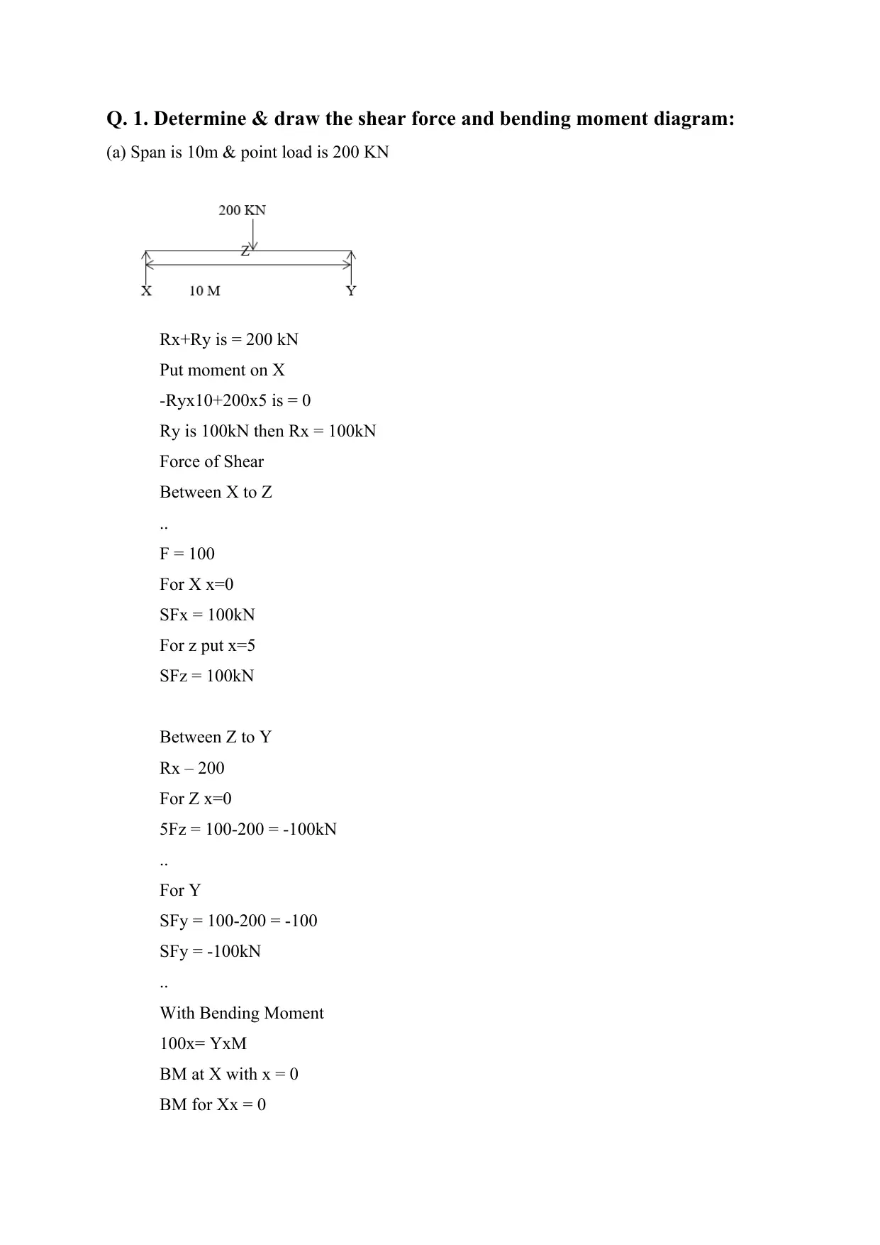
(a) Span is 10m & point load is 200 KN
Rx+Ry is = 200 kN
Put moment on X
-Ryx10+200x5 is = 0
Ry is 100kN then Rx = 100kN
Force of Shear
Between X to Z
..
F = 100
For X x=0
SFx = 100kN
For z put x=5
SFz = 100kN
Between Z to Y
Rx – 200
For Z x=0
5Fz = 100-200 = -100kN
..
For Y
SFy = 100-200 = -100
SFy = -100kN
..
With Bending Moment
100x= YxM
BM at X with x = 0
BM for Xx = 0
Paraphrase This Document
Need a fresh take? Get an instant paraphrase of this document with our AI Paraphraser
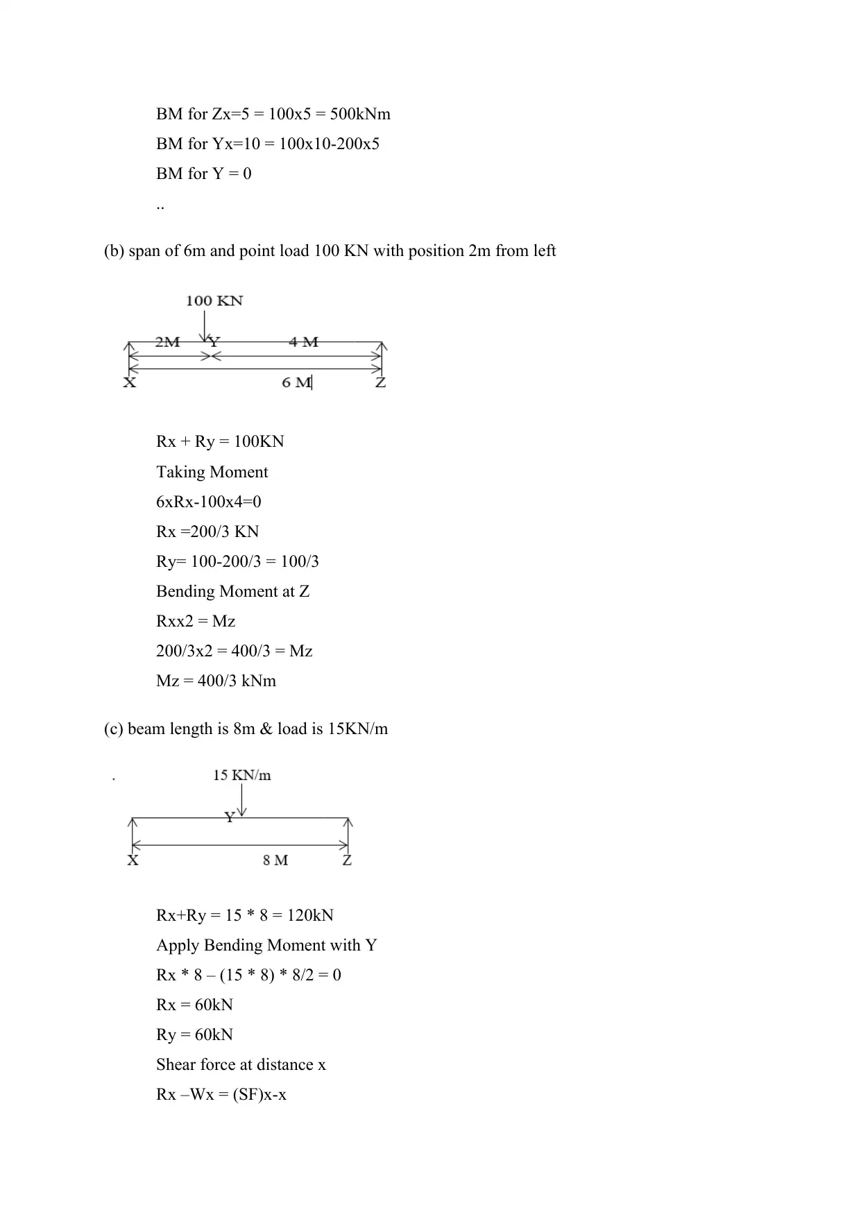
BM for Zx=5 = 100x5 = 500kNm
BM for Yx=10 = 100x10-200x5
BM for Y = 0
..
(b) span of 6m and point load 100 KN with position 2m from left
Rx + Ry = 100KN
Taking Moment
6xRx-100x4=0
Rx =200/3 KN
Ry= 100-200/3 = 100/3
Bending Moment at Z
Rxx2 = Mz
200/3x2 = 400/3 = Mz
Mz = 400/3 kNm
(c) beam length is 8m & load is 15KN/m
Rx+Ry = 15 * 8 = 120kN
Apply Bending Moment with Y
Rx * 8 – (15 * 8) * 8/2 = 0
Rx = 60kN
Ry = 60kN
Shear force at distance x
Rx –Wx = (SF)x-x
60-15*4 = 0
Bending Moment at x-x
Ra x x – Wx/2 = Mx
At mid x = 4
60 * 4 – (15 * 4 * 4)/2
=120kNm
Mid Bending Moment = 120kNm
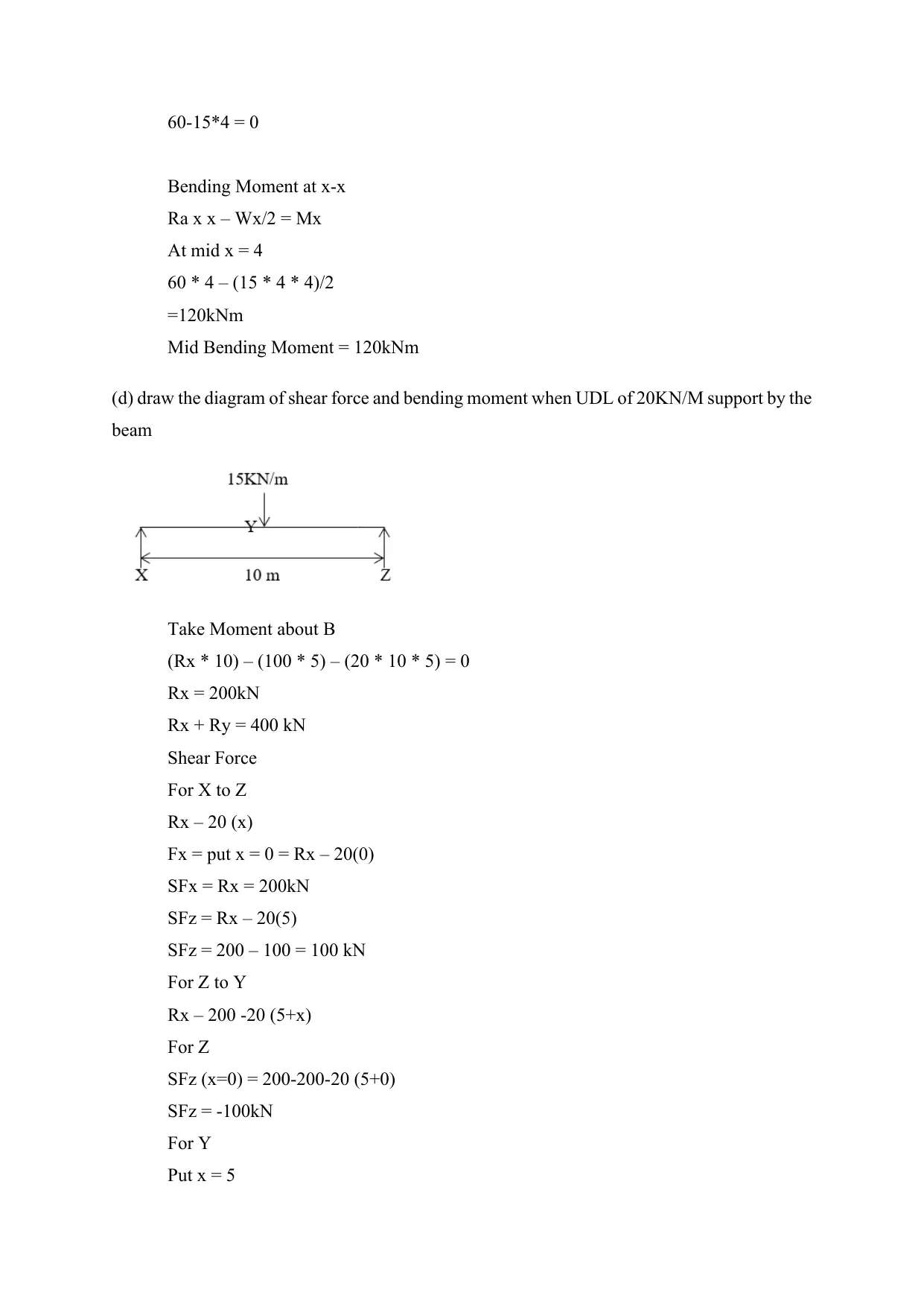
(d) draw the diagram of shear force and bending moment when UDL of 20KN/M support by the
beam
Take Moment about B
(Rx * 10) – (100 * 5) – (20 * 10 * 5) = 0
Rx = 200kN
Rx + Ry = 400 kN
Shear Force
For X to Z
Rx – 20 (x)
Fx = put x = 0 = Rx – 20(0)
SFx = Rx = 200kN
SFz = Rx – 20(5)
SFz = 200 – 100 = 100 kN
For Z to Y
Rx – 200 -20 (5+x)
For Z
SFz (x=0) = 200-200-20 (5+0)
SFz = -100kN
For Y
Put x = 5
Bending Moment at x-x
Ra x x – Wx/2 = Mx
At mid x = 4
60 * 4 – (15 * 4 * 4)/2
=120kNm
Mid Bending Moment = 120kNm
(d) draw the diagram of shear force and bending moment when UDL of 20KN/M support by the
beam
Take Moment about B
(Rx * 10) – (100 * 5) – (20 * 10 * 5) = 0
Rx = 200kN
Rx + Ry = 400 kN
Shear Force
For X to Z
Rx – 20 (x)
Fx = put x = 0 = Rx – 20(0)
SFx = Rx = 200kN
SFz = Rx – 20(5)
SFz = 200 – 100 = 100 kN
For Z to Y
Rx – 200 -20 (5+x)
For Z
SFz (x=0) = 200-200-20 (5+0)
SFz = -100kN
For Y
Put x = 5
⊘ This is a preview!⊘
Do you want full access?
Subscribe today to unlock all pages.
Trusted by 1+ million students worldwide
SFy = 200-200-200
SFy = -200kN
..
Bending Moment
BM at X
(100 * 5) – (20 * 5 * 5/2)
= 750kNm
BM at Y
(200 * 10) – (200 * 5) – (20 * 5 * 2.5)
= -1000kNm
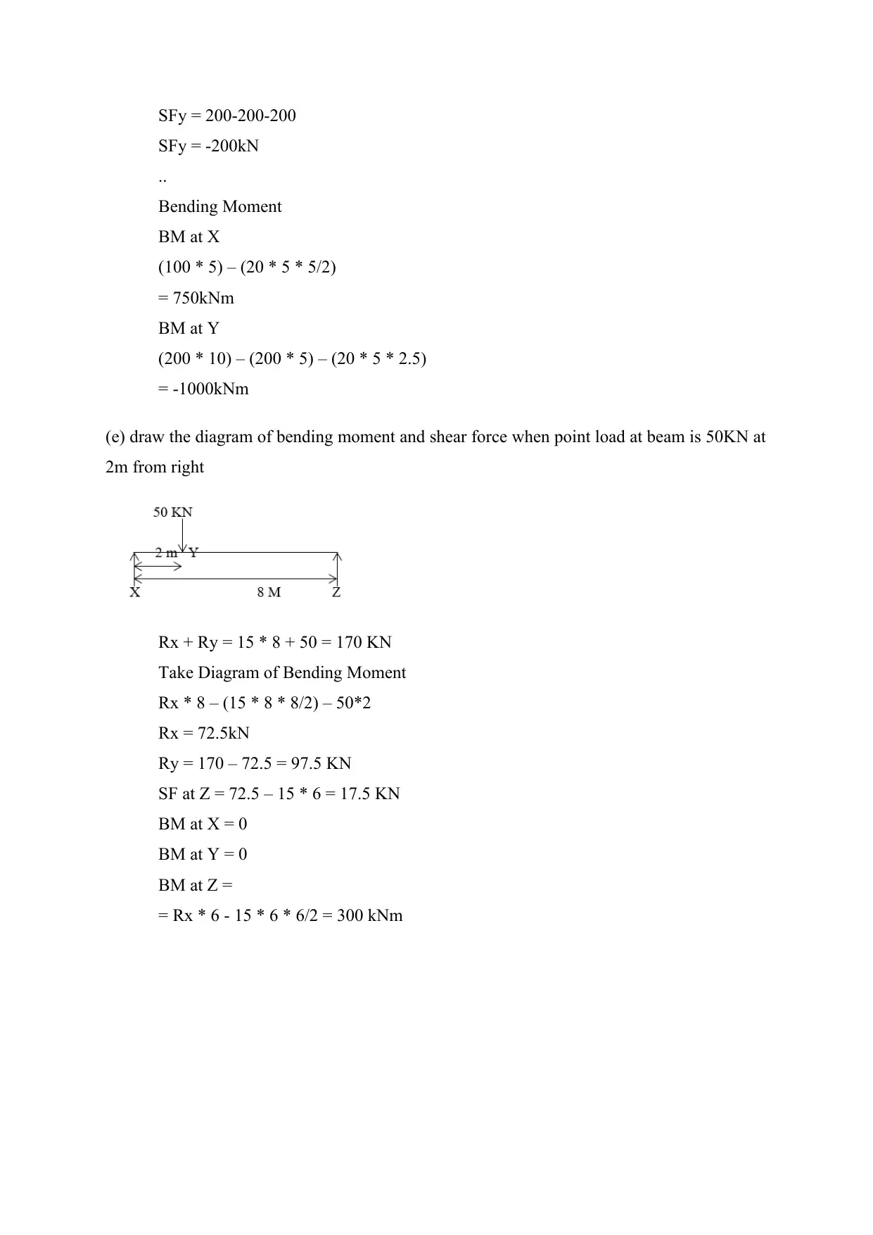
(e) draw the diagram of bending moment and shear force when point load at beam is 50KN at
2m from right
Rx + Ry = 15 * 8 + 50 = 170 KN
Take Diagram of Bending Moment
Rx * 8 – (15 * 8 * 8/2) – 50*2
Rx = 72.5kN
Ry = 170 – 72.5 = 97.5 KN
SF at Z = 72.5 – 15 * 6 = 17.5 KN
BM at X = 0
BM at Y = 0
BM at Z =
= Rx * 6 - 15 * 6 * 6/2 = 300 kNm
SFy = -200kN
..
Bending Moment
BM at X
(100 * 5) – (20 * 5 * 5/2)
= 750kNm
BM at Y
(200 * 10) – (200 * 5) – (20 * 5 * 2.5)
= -1000kNm
(e) draw the diagram of bending moment and shear force when point load at beam is 50KN at
2m from right
Rx + Ry = 15 * 8 + 50 = 170 KN
Take Diagram of Bending Moment
Rx * 8 – (15 * 8 * 8/2) – 50*2
Rx = 72.5kN
Ry = 170 – 72.5 = 97.5 KN
SF at Z = 72.5 – 15 * 6 = 17.5 KN
BM at X = 0
BM at Y = 0
BM at Z =
= Rx * 6 - 15 * 6 * 6/2 = 300 kNm
Paraphrase This Document
Need a fresh take? Get an instant paraphrase of this document with our AI Paraphraser
Q. 2. Identify different methods of supports for structures:
Supports: a member of the structure that helps to resists load like the other member. The
supports have different types, applications and reactions that define below. It used to define the
forces in different terms like how the forces transferred to the ground. Here defines different
example of the supports with their example, limitations and reaction.
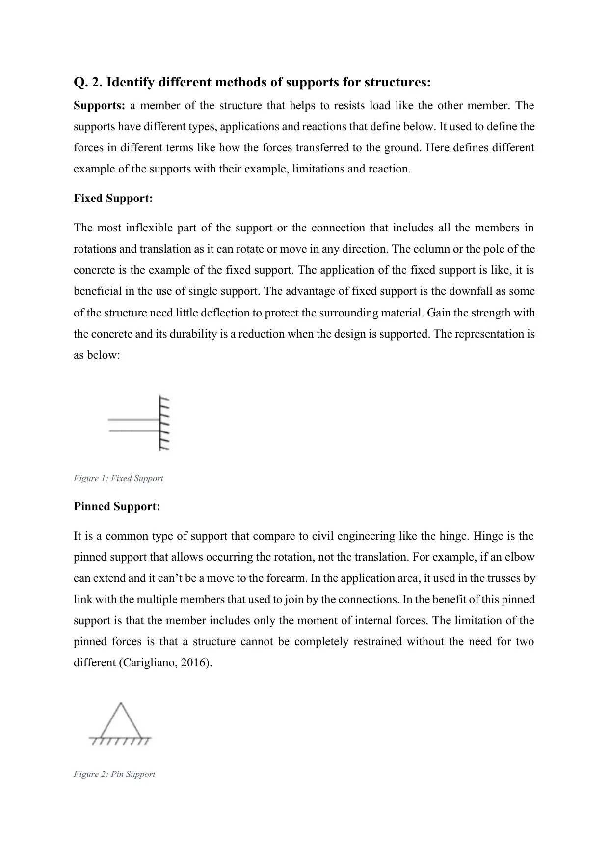
Fixed Support:
The most inflexible part of the support or the connection that includes all the members in
rotations and translation as it can rotate or move in any direction. The column or the pole of the
concrete is the example of the fixed support. The application of the fixed support is like, it is
beneficial in the use of single support. The advantage of fixed support is the downfall as some
of the structure need little deflection to protect the surrounding material. Gain the strength with
the concrete and its durability is a reduction when the design is supported. The representation is
as below:
Figure 1: Fixed Support
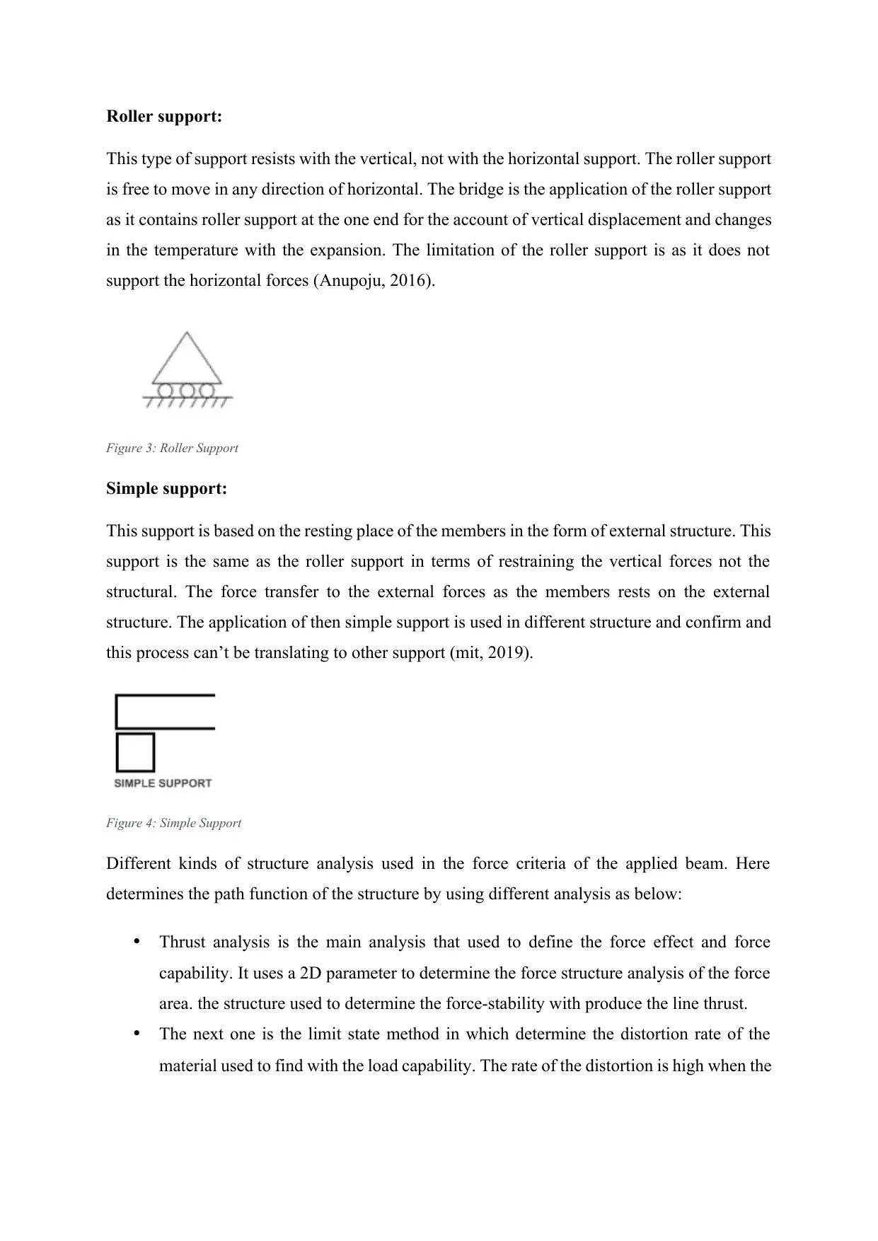
Pinned Support:
It is a common type of support that compare to civil engineering like the hinge. Hinge is the
pinned support that allows occurring the rotation, not the translation. For example, if an elbow
can extend and it can’t be a move to the forearm. In the application area, it used in the trusses by
link with the multiple members that used to join by the connections. In the benefit of this pinned
support is that the member includes only the moment of internal forces. The limitation of the
pinned forces is that a structure cannot be completely restrained without the need for two
different (Carigliano, 2016).
Figure 2: Pin Support
Supports: a member of the structure that helps to resists load like the other member. The
supports have different types, applications and reactions that define below. It used to define the
forces in different terms like how the forces transferred to the ground. Here defines different
example of the supports with their example, limitations and reaction.
Fixed Support:
The most inflexible part of the support or the connection that includes all the members in
rotations and translation as it can rotate or move in any direction. The column or the pole of the
concrete is the example of the fixed support. The application of the fixed support is like, it is
beneficial in the use of single support. The advantage of fixed support is the downfall as some
of the structure need little deflection to protect the surrounding material. Gain the strength with
the concrete and its durability is a reduction when the design is supported. The representation is
as below:
Figure 1: Fixed Support
Pinned Support:
It is a common type of support that compare to civil engineering like the hinge. Hinge is the
pinned support that allows occurring the rotation, not the translation. For example, if an elbow
can extend and it can’t be a move to the forearm. In the application area, it used in the trusses by
link with the multiple members that used to join by the connections. In the benefit of this pinned
support is that the member includes only the moment of internal forces. The limitation of the
pinned forces is that a structure cannot be completely restrained without the need for two
different (Carigliano, 2016).
Figure 2: Pin Support
Roller support:
This type of support resists with the vertical, not with the horizontal support. The roller support
is free to move in any direction of horizontal. The bridge is the application of the roller support
as it contains roller support at the one end for the account of vertical displacement and changes
in the temperature with the expansion. The limitation of the roller support is as it does not
support the horizontal forces (Anupoju, 2016).
Figure 3: Roller Support
Simple support:
This support is based on the resting place of the members in the form of external structure. This
support is the same as the roller support in terms of restraining the vertical forces not the
structural. The force transfer to the external forces as the members rests on the external
structure. The application of then simple support is used in different structure and confirm and
this process can’t be translating to other support (mit, 2019).
Figure 4: Simple Support
Different kinds of structure analysis used in the force criteria of the applied beam. Here
determines the path function of the structure by using different analysis as below:
Thrust analysis is the main analysis that used to define the force effect and force
capability. It uses a 2D parameter to determine the force structure analysis of the force
area. the structure used to determine the force-stability with produce the line thrust.
The next one is the limit state method in which determine the distortion rate of the
material used to find with the load capability. The rate of the distortion is high when the
⊘ This is a preview!⊘
Do you want full access?
Subscribe today to unlock all pages.
Trusted by 1+ million students worldwide
capacity of load increase. On the other side, the time distortion is less when the load
capacity is low.
The model of finite element used to find the heating element of the structure of the
material in which the material degree of freedom depends on the structure value of
displacement.
Steel and reinforced structure:
The steel structure has a different parameter that used for the different purpose as per their load
capacity. Structural steel is versatile and flexible material as it used to construct the different
impossible and expensive bridge. The steel used for different purposes like constriction,
transport, packaging, manufacturing, transport, energy, shipbuilding and many more purpose.
Steel found in different shapes like, S shape that is known as American standard beam, L-shape
(angle), H-shape (bearing pile) and channel (C-shape) and HSS (Hollow steel section)
(Brakefield, 2017).
On the other side, reinforced concrete is the combination of two different materials that act
together with using different forces. the concrete structure of the reinforced structure includes
the rods, mesh-absorbs shear and tensile for the construction purpose. It recognised as the
lightweight, eliminate the problems of deterioration and high strength with nonmagnets (Kalfat,
R. and Al-Mahaidi, R., 2010).
Paraphrase This Document
Need a fresh take? Get an instant paraphrase of this document with our AI Paraphraser
Q. 3. Produce valid factors for live loads, dead loads and imposed loads
The factor of safety:
The factors of safety are related to the carrying load of the capacity of a system beyond the
capacity of the system support. This process used in the construction of bridges, buildings,
safety equipment and fall protection. this process used to define the requirements of the
stronger system for the construction. Determine the factor of safety with the strength tests and
how much the weight can be managed by the system. the safety factor determines by the ductile
material with use the yield strength. On the other side, the ultimate strength uses by the brittle
material (Wilhite, 2018).
Safety for live load:
This load is also known as imposed load and this is usually dynamic, temporary and
changeable. This kind of load used in vehicle traffic, furniture, occupants and in the other
equipment’s. this load includes the intensity that depends on the time of the day. Understanding
with an example, an office building increases the live load at the weekday compare to the less
load at weekends or night. The live load involves or include in the impact with the vibration or
the acceleration is related to the distributed and concentrated.
Safety for dead load:
These loads are the static or permanent loads that connected with the weight of the structure and
this weight remains constant over time. The structural elements weight includes in the dead
load along with the partitions of permanents non-structural and the plasterboard as the
immovable fixtures (Designingbuildings, 2019). Dead loads used to calculate the weight by
accessing the specific materials. It is also possible to calculate the dead loads with a good
degree of accuracy. Dead loads with the structural engineers are estimates constructive.
Safety for imposed load:
Imposed load area the applied load on building and streets that arise for the purpose of building
of service life. The value of the imposed loads categorises into the section as per the values of
floor and structure. This kind of load is not the permanent load and can change as per the load
capacity with the distraction rate (Bd.gov, 2011).
Building regulation and Code of practice:
The design structure of the material is responsible for the code of practice for live loads. The
surface rate changes the applied load with the deformation of the applied structure and this
process related to the material of the load structure. The deformation rate of the part of the
material is low and this occurs on the safety factor on the time with the design structure of the
material. The complete weight of the structure depends on the dead load application that used to
build the depending regulation. The code of practice that relates to the dead load depends on the
structural panel with the basic design.
Q. 4. Discuss design responsibilities under CDM regulations:
CDM (Construction design and management) is like an organization or the individual business
that involve in modifying or preparing the designs of the construction projects. It also
instruction and the arrangements in the design construction. These designs include the design
calculations, drawings, specifications, the quantity of bills with detail of designs. The designers
are the constructors, architects, engineers, interior designers and the quantity surveyors or
anyone related to the construction area used to manage the design as specific or alter them. This
is done as their work or responsibility (Hse.gov, 2019).
The CDM 2015 used to define the roles and principles of the designers. Here are some facts
about the role of principles designer as:
It can be appointed only one principle designer at one time
More then one contractor is required on any project by the principal designer
the health and safety of the preconstruction phase is the responsibility of the principle’s
designer
the phases of the preconstruction control by the principles designer that defines in the CDM
2015. This phase includes all the information about the project from its starting to ending. The
principle designer leads the project with proper planning and design. Different phases of the
project managed by the principle designer like, planning, monitoring and managing the
preconstruction phase of a project. the duties of the principle designer are like:
Make a proper plan, monitoring and managing the phase of preconstruction
Make the risk management plans related to the health and safety project and manage the
phase so that the project can be delivered on time
⊘ This is a preview!⊘
Do you want full access?
Subscribe today to unlock all pages.
Trusted by 1+ million students worldwide
1 out of 24
Related Documents


Your All-in-One AI-Powered Toolkit for Academic Success.
+13062052269
info@desklib.com
Available 24*7 on WhatsApp / Email
![[object Object]](/_next/static/media/star-bottom.7253800d.svg)
Unlock your academic potential
Copyright © 2020–2026 A2Z Services. All Rights Reserved. Developed and managed by ZUCOL.