Detailed Structural Design and Analysis of Slabs, Beams, and Columns

Verified

Added on  2021/04/21

|41
|1318
|457
Practical Assignment
AI Summary
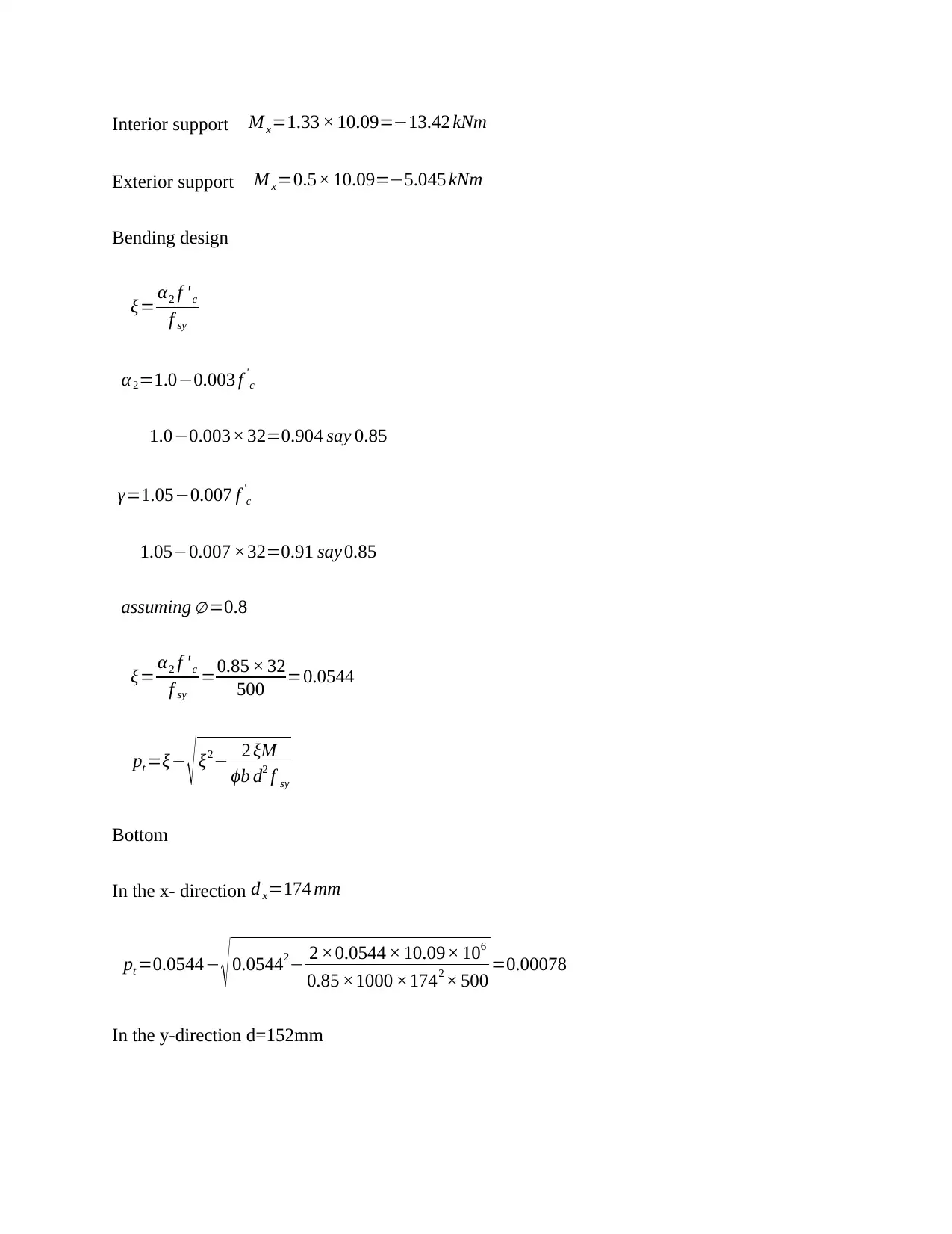
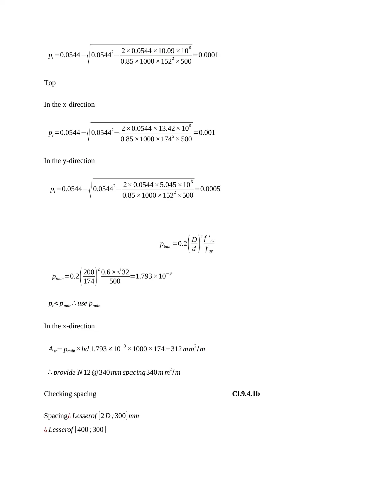
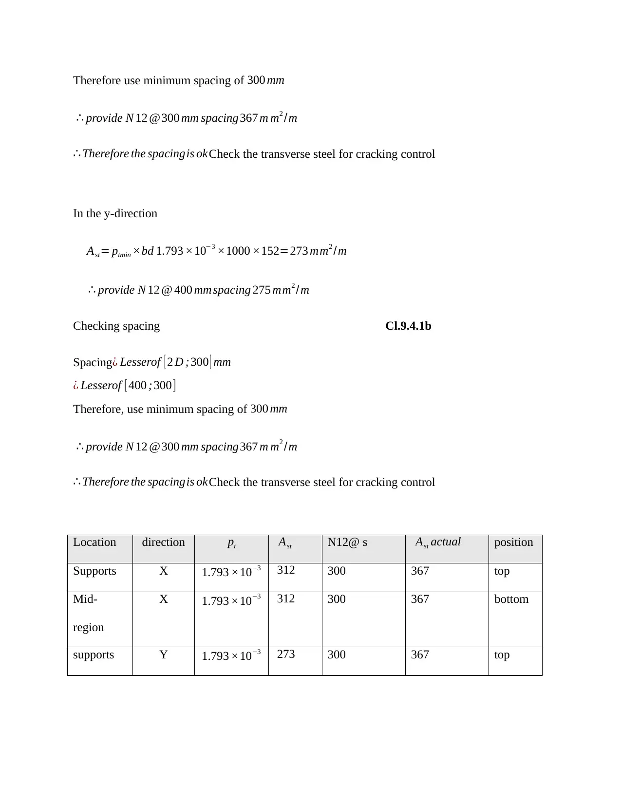
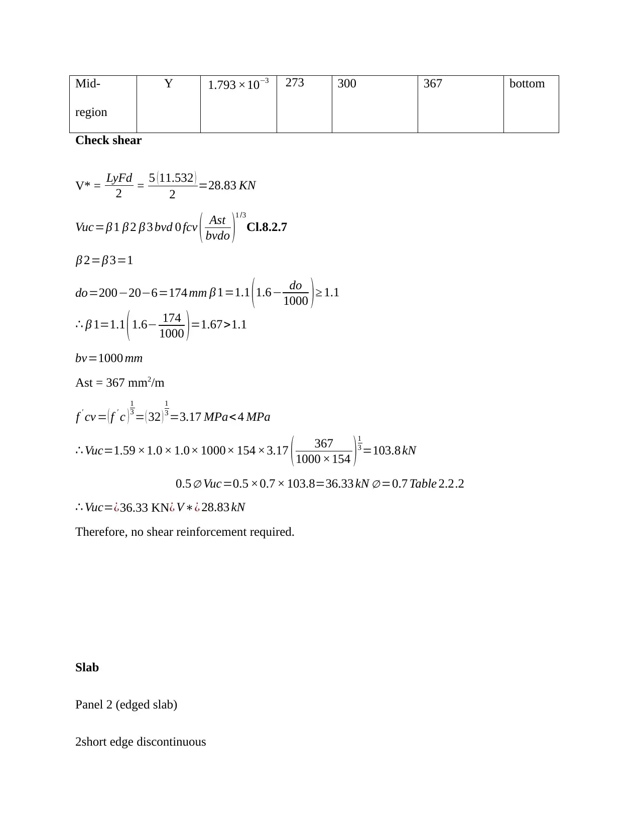
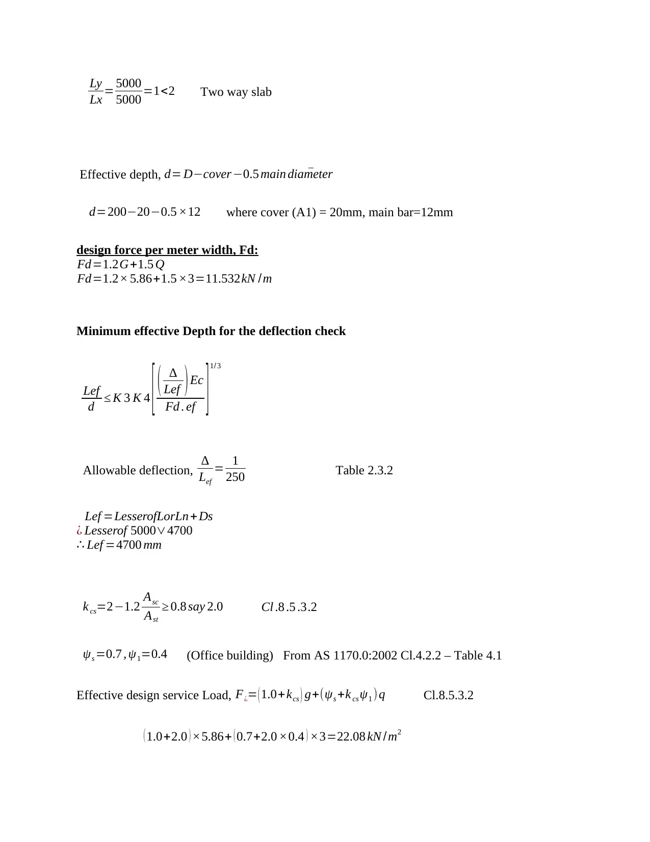
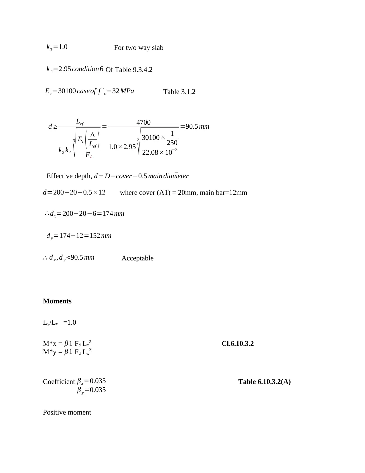
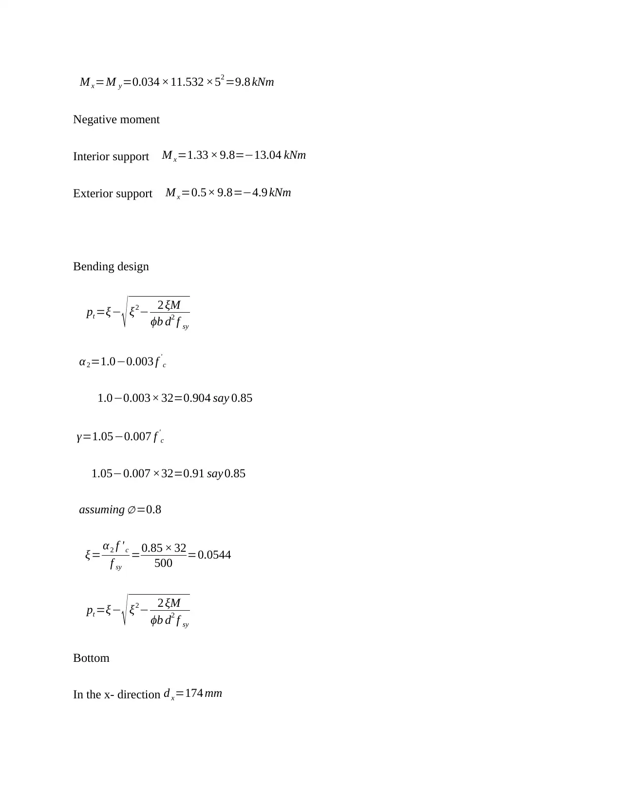
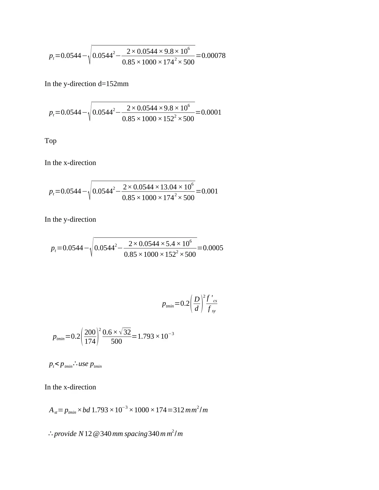
This document presents a comprehensive structural design analysis, covering the design of slab panels, beams, and columns. The slab design includes calculations for both corner and edged slabs, detailing load combinations, effective depths, bending moments, and reinforcement requirements for both top and bottom steel, as well as shear checks. Beam design focuses on continuous and simply supported beams, incorporating deflection checks, bending moment calculations, shear force analysis, and the determination of required reinforcement. The column design involves the analysis of axial compression, bending capacity, and the construction of an interaction diagram to assess the structural behavior under combined loading conditions. The analysis adheres to relevant Australian Standards (AS 3600) and includes detailed calculations for various load cases, ensuring structural integrity and compliance with design codes. The document provides a thorough examination of each structural element, offering insights into the design process and essential considerations for civil engineering applications.
Document Page
Layout plan
tabler-icon-diamond-filled.svg

Paraphrase This Document

Need a fresh take? Get an instant paraphrase of this document with our AI Paraphraser
Document Page
Loading
Super imposed = 1.0kpa
Live Load= 3.0kpa
ρw =24+0.6 v assume v=0.5%
¿ 24 × 0.6 ×05=24.3
gk = ( 24.3× 0.2 ) +1 =5.86kpa
qk=¿ 3.0 kpa
Load combination
ULS=1.2 gk +1.5 qk
1.2 ×5.86+1.5 ×3=11.532
Slab
Panel 1 (corner slab)
2 adjacent continuous
Ly
Lx = 5000
5000 =1<2
Document Page
design force per meter width, Fd:
Fd=1.2G+1.5 Q
Fd=1.2× 5.86+1.5 ×3=11.532kN /m
Minimum effective Depth for the deflection check
Lef
d K 3 K 4 [ (
Lef )Ec
Fd . ef ]1/ 3
Allowable deflection,
Lef
= 1
250 Table 2.3.2
Lef =LesserofLorLn +Ds
¿ Lesserof 50004700
Lef =4700 mm
k cs=21.2 Asc
Ast
0.8 say 2.0 Cl .8 .5 .3.2
ψs =0.7 , ψ1=0.4 (Office building) From AS 1170.0:2002 Cl.4.2.2 – Table 4.1
Effective design service Load, F¿= ( 1.0+kcs ) g+(ψs +k cs ψ1 ) q Cl.8.5.3.2
( 1.0+2.0 ) ×5.86+ ( 0.7+2.0 ×0.4 ) ×3=22.08 kN /m2
k3 =1.0 For two way slab
k 4=2.95 condition 6 Of Table 9.3.4.2
Ec=30100 caseof f ' c=32 MPa Table 3.1.2
Document Page
d Lef
k3 k 4
3
Ec (
Lef )
F¿
= 4700
1.0× 2.95
3
30100 × 1
250
22.08 × 103
=90.5 mm
Effective depth, d= Dcover 0.5 main ¯diameter
d=200200.5 ×12 where cover (A1) = 20mm, main bar=12mm
dx=200206=174 mm
d y=17412=152 mm
d x , d y <90.5 mm Acceptable
Moments
Ly/Lx =1.0
M*x = β 1 Fd Lx2 Cl.6.10.3.2
M*y = β 1 Fd Lx2
Coefficient βx=0.035 Table 6.10.3.2(A)
β y=0.035
Positive moment
M x
¿=0.035× 11.532× 52=10.09 kNm
M y
¿ =0.035 ×11.532 ×52=10.09 kNm
Negative moment (supports ) Cl.6.10.3.2 (B & C)
tabler-icon-diamond-filled.svg

Paraphrase This Document

Need a fresh take? Get an instant paraphrase of this document with our AI Paraphraser
Document Page
Interior support Mx=1.33 × 10.09=13.42 kNm
Exterior support M x=0.5× 10.09=5.045 kNm
Bending design
ξ= α2 f 'c
f sy
α2=1.00.003 f '
c
1.00.003× 32=0.904 say 0.85
γ=1.050.007 f '
c
1.050.007 ×32=0.91 say 0.85
assuming =0.8
ξ= α2 f 'c
f sy
=0.85 × 32
500 =0.0544
pt =ξ ξ2 2 ξM
ϕb d2 f sy
Bottom
In the x- direction d x=174 mm
pt =0.0544 0.05442 2 ×0.0544 × 10.09× 106
0.85 ×1000 ×1742 × 500 =0.00078
In the y-direction d=152mm
Document Page
pt =0.0544 0.05442 2× 0.0544 ×10.09 ×106
0.85 ×1000 ×1522 ×500 =0.0001
Top
In the x-direction
pt =0.0544 0.05442 2 ×0.0544 × 13.42× 106
0.85 ×1000 ×1742 × 500 =0.001
In the y-direction
pt =0.0544 0.05442 2× 0.0544 ×5.045 ×106
0.85 ×1000 ×1522 ×500 =0.0005
ptmin =0.2 ( D
d )2 f 'cs
f sy
ptmin =0.2 ( 200
174 )
2 0.6 × 32
500 =1.793 ×10³
pt < ptmin use ptmin
In the x-direction
Ast= ptmin ×bd 1.793 ×103 ×1000 ×174=312 mm2 /m
provide N 12 @340 mm spacing340 m m2 /m
Checking spacing Cl.9.4.1b
Spacing ¿ Lesserof [ 2 D ; 300 ] mm
¿ Lesserof [400 ; 300]
Document Page
Therefore use minimum spacing of 300 mm
provide N 12 @300 mm spacing367 m m2 /m
Therefore the spacingis okCheck the transverse steel for cracking control
In the y-direction
Ast= ptmin ×bd 1.793 ×103 ×1000 ×152=273 mm2 /m
provide N 12 @ 400 mm spacing 275 mm2 /m
Checking spacing Cl.9.4.1b
Spacing ¿ Lesserof [ 2 D ; 300 ] mm
¿ Lesserof [400 ; 300]
Therefore, use minimum spacing of 300 mm
provide N 12 @300 mm spacing367 m m2 /m
Therefore the spacingis okCheck the transverse steel for cracking control
Location direction pt Ast N12@ s Ast actual position
Supports X 1.793 ×10³ 312 300 367 top
Mid-
region
X 1.793 ×10³ 312 300 367 bottom
supports Y 1.793 ×10³ 273 300 367 top
tabler-icon-diamond-filled.svg

Paraphrase This Document

Need a fresh take? Get an instant paraphrase of this document with our AI Paraphraser
Document Page
Mid-
region
Y 1.793 ×10³ 273 300 367 bottom
Check shear
V* = LyFd
2 = 5 ( 11.532 )
2 =28.83 KN
Vuc=β 1 β 2 β 3 bvd 0 fcv ( Ast
bvdo )
1 /3
Cl.8.2.7
β 2=β 3=1
do=200206=174 mm β 1=1.1 (1.6 do
1000 ) 1.1
β 1=1.1 (1.6 174
1000 )=1.67>1.1
bv=1000 mm
Ast = 367 mm2/m
f ' cv = ( f ' c )
1
3 = ( 32 )
1
3 =3.17 MPa< 4 MPa
Vuc=1.59 ×1.0 × 1.0× 1000× 154 ×3.17 ( 367
1000 ×154 ) 1
3 =103.8 kN
0.5 Vuc=0.5 ×0.7 × 103.8=36.33 kN =0.7 Table 2.2.2
Vuc=¿36.33 KN¿ V¿ 28.83 kN
Therefore, no shear reinforcement required.
Slab
Panel 2 (edged slab)
2short edge discontinuous
Document Page
Ly
Lx = 5000
5000 =1<2 Two way slab
Effective depth, d= Dcover 0.5 main ¯diameter
d=200200.5 ×12 where cover (A1) = 20mm, main bar=12mm
design force per meter width, Fd:
Fd=1.2G+1.5 Q
Fd=1.2× 5.86+1.5 ×3=11.532kN /m
Minimum effective Depth for the deflection check
Lef
d K 3 K 4 [ (
Lef )Ec
Fd . ef ]1/ 3
Allowable deflection,
Lef
= 1
250 Table 2.3.2
Lef =LesserofLorLn +Ds
¿ Lesserof 50004700
Lef =4700 mm
k cs=21.2 Asc
Ast
0.8 say 2.0 Cl .8 .5 .3.2
ψs =0.7 , ψ1=0.4 (Office building) From AS 1170.0:2002 Cl.4.2.2 – Table 4.1
Effective design service Load, F¿= ( 1.0+kcs ) g+(ψs +k cs ψ1 ) q Cl.8.5.3.2
( 1.0+2.0 ) ×5.86+ ( 0.7+2.0 ×0.4 ) ×3=22.08 kN /m2
Document Page
k3 =1.0 For two way slab
k 4=2.95 condition 6 Of Table 9.3.4.2
Ec=30100 caseof f ' c=32 MPa Table 3.1.2
d Lef
k3 k 4
3
Ec (
Lef )
F¿
= 4700
1.0× 2.95
3
30100 × 1
250
22.08 × 103
=90.5 mm
Effective depth, d= Dcover 0.5 main ¯diameter
d=200200.5 ×12 where cover (A1) = 20mm, main bar=12mm
dx=200206=174 mm
d y=17412=152 mm
d x , d y <90.5 mm Acceptable
Moments
Ly/Lx =1.0
M*x = β 1 Fd Lx2 Cl.6.10.3.2
M*y = β 1 Fd Lx2
Coefficient βx=0.035 Table 6.10.3.2(A)
β y=0.035
Positive moment
tabler-icon-diamond-filled.svg

Paraphrase This Document

Need a fresh take? Get an instant paraphrase of this document with our AI Paraphraser
Document Page
M x=M y=0.034 ×11.532 ×52 =9.8 kNm
Negative moment
Interior support M x=1.33 × 9.8=13.04 kNm
Exterior support M x=0.5× 9.8=4.9 kNm
Bending design
pt =ξ ξ2 2 ξM
ϕb d2 f sy
α2=1.00.003 f '
c
1.00.003× 32=0.904 say 0.85
γ=1.050.007 f '
c
1.050.007 ×32=0.91 say 0.85
assuming =0.8
ξ= α2 f 'c
f sy
=0.85 × 32
500 =0.0544
pt =ξ ξ2 2 ξM
ϕb d2 f sy
Bottom
In the x- direction d x=174 mm
Document Page
pt =0.0544 0.05442 2× 0.0544 × 9.8× 106
0.85 ×1000 ×1742 × 500 =0.00078
In the y-direction d=152mm
pt =0.0544 0.05442 2× 0.0544 ×9.8 × 106
0.85 ×1000 ×1522 ×500 =0.0001
Top
In the x-direction
pt =0.0544 0.05442 2× 0.0544 ×13.04 × 106
0.85 ×1000 ×1742 × 500 =0.001
In the y-direction
pt =0.0544 0.05442 2× 0.0544 ×5.4 × 106
0.85 ×1000 ×1522 ×500 =0.0005
ptmin =0.2 ( D
d )2 f 'cs
f sy
ptmin =0.2 ( 200
174 )
2 0.6 × 32
500 =1.793 ×10³
pt < ptmin use ptmin
In the x-direction
Ast= ptmin ×bd 1.793 ×103 ×1000 ×174=312 mm2 /m
provide N 12 @340 mm spacing340 m m2 /m
Document Page
Checking spacing Cl.9.4.1b
Spacing ¿ Lesserof [ 2 D ; 300 ] mm
¿ Lesserof [400 ; 300]
Therefore, use minimum spacing of 300 mm
provide N 12 @300 mm spacing367 m m2 /m
In the y-direction
Ast= ptmin ×bd 1.793 ×103 ×1000 ×152=273 mm2 /m
provide N 12 @ 400 mm spacing 275 mm2 /m
Checking spacing Cl.9.4.1b
Spacing ¿ Lesserof [ 2 D ; 300 ] mm
¿ Lesserof [400 ; 300]
Therefore, use minimum spacing of 300 mm
provide N 12 @300 mm spacing367 m m2 /m
Therefore the spacingis okCheck the transverse steel for cracking control
Location direction pt Ast N12@ s Ast actual position
Supports X 1.793 ×10³ 312 300 367 top
Mid-
region
X 1.793 ×10³ 312 300 367 bottom
tabler-icon-diamond-filled.svg

Paraphrase This Document

Need a fresh take? Get an instant paraphrase of this document with our AI Paraphraser
Document Page
supports Y 1.793 ×10³ 273 300 367 top
Mid-
region
Y 1.793 ×10³ 273 300 367 bottom
Check shear
V* = LyFd
2 = 5 ( 11.532 )
2 =28.83 KN
Vuc=β 1 β 2 β 3 bvd 0 fcv ( Ast
bvdo )
1 /3
Cl.8.2.7
β 2=β 3=1
do=200206=174 mm β 1=1.1 (1.6 do
1000 ) 1.1
β 1=1.1 (1.6 174
1000 )=1.67>1.1
bv=1000 mm
Ast = 367 mm2/m
f ' cv = ( f ' c )
1
3 = ( 32 )
1
3 =3.17 MPa< 4 MPa
Vuc=1.59 ×1.0 × 1.0× 1000× 154 ×3.17 ( 367
1000 ×154 )1
3 =103.8 kN
0.5 Vuc=0.5 ×0.7 × 103.8=36.33 kN =0.7 Table 2.2.2
Vuc=¿36.33 KN¿ V¿ 28.83 kN
Therefore, no shear reinforcement required.
Beam
Load transfers
Document Page
Load transfer figure from AS 3600 figure 7.3.4
Edge beams
Continuous Beam B1 (L Beam)
Given Details:
Beam Width , b=500 mm
Assuming beam depth, D=500 mm
Therefore:
d= Dcover stirruphalfthediameterofthebar
d=5004012 16
2 =440 mm
Dead Load, G= 5 ×0.2 ×24
4 + ( 0.5× 0.3 ×24 )+ 1 ×1
4 =10 kPa
Live Load, Q=3.0 kPa
The load conditions that are considered:
w=1.2 G+ 1.5Q
W = ( 1.2× 10 ) + ( 1.5× 3 )
Document Page
W=16.5 kN /m
External Beam (continuous Beam)
Continuous beam with 3 equal spans
Moment, M ¿=αF l2 where l is the clear length, 4500
Figure showing Factors of moment
Supports (A, B)
Mid-span (C, D)
Shear Force, V ¿=βFl
tabler-icon-diamond-filled.svg

Paraphrase This Document

Need a fresh take? Get an instant paraphrase of this document with our AI Paraphraser
Document Page
Figure showing Factors of shear force
α M ¿=αF l2
(kNm)
β V ¿=βFl
kN
A -1/16 -20.88 ½ 37.13
C +1/11 +30.38 1/7 10.61
B1 -1/10 -33.41 1.15/2 42.70
B2 -1/10 -33.41 ½ 37.13
D +1/16 20.88 1/8 9.28
Deflection check:
Using deemed to comply ratio, according to AS3600, Cl.8.5.4
Document Page
Lef
d [ K 1 ( Δ
L ef ) befEc
K 2 Fd , ef ] 1
3
Lef =LesserofLorLn + Ds
Where : ln=L2 × ( 500
2 )=5000500=4500 mm
Lef =Lesserof [ 5000 ; 4500+200 ]
¿ Lesserof [5000 ; 4700]
Lef =4700 mm

Lef = 1
250 Table 2.3.2
Ec=30100 MPa , when f ' c=32 MPa Table 3.1.2
Fd , ef =effective design service load :
Fd , ef = ( 1+Kcs ) G+ ( Ψs+ KcsΨL ) Q
Where:
Kcs=
[ 21.2 ( Asc
Ast ) ] 0.8 Cl.8.5.3.2
Kcs=2>0.8 Cl.4.2.2 – Table 4.1
Ψs=0.7and ΨL=0.4 (Floor for an office building)
Fd , ef = (1+2 ) 10+¿
K1:
P=0.005¿ AS 3600
β= bef
bw
Where:
bw=500 mm
bef =bw+0.1 aCl.8.8b
a=0.7 L (For Continuous Beam)
a=0.7 ×5000=3500 mm
Document Page
So, bef =500+ ( 0.1 ×3500 )=850 mm
β= 850
500 =1.7
So,
p=0.005>0.001 ( f ' c )
1
3
( β )
2
3
= 0.001× ( 32 )
1
3
( 1.7 )
2
3
=0.0022
Therefore: K 1= ( 50.04 f ' c ) p+0.0022 0.1
( β )
2
3
K 1= ( 50.04 ×32 ) 0.005+0.0022 0.1
( 1.7 )
2
3
K 1=0.0208<0.0702
K 2= 2.4
384
Lef
d [ K 1 ( Δ
L ef ) befEc
K 2 Fd , ef ] 1
3
4700
440
[ 0.0208 × ( 1
250 ) × 850 ×30100
( 2.4
384 ) × 34.5 ] 1
3
15.2<21.4
Hence ,the deflection ˇis ok
Bending Check
tabler-icon-diamond-filled.svg

Paraphrase This Document

Need a fresh take? Get an instant paraphrase of this document with our AI Paraphraser
Document Page
Ast=4 × ( π
4 ) × ( 16 ) 2=804 mm2
Asc=4 × ( π
4 )× ( 16 )2 =804 m m2
f ' c=32 MPa
fsy=500 MPa
α 2=10.003 f ' c AS3600 Cl.8.1.3
¿ 1 ( 0.003× 32 )
¿ 0.904 say 0.85limits 0.67 α 0.85
γ=1.050.007 f ' c
¿ 1.05 ( 0.007 ×32 )
¿ 0.826 within the limits0.67 γ 0.85
So, α 2=0.85γ =0.826
Assuming Tensile Steel yields:
C= ( α 2 f ' c )( γ Kud)bef
C=0.85 ×32 ×0.826 × 850× Kud=19097.12 Kud
T = Astfsy
T =804 × 500=402× 103 N
For equilibrium, C=T
19097.12 Kud=402× 103
Document Page
dn= Kud=21.1 mm
0.003
dn = ε st
ddn
0.003
21.1 = ε st
44021.1
ε st=0.06> ε sy=0.0025 Where: ε sy= ( fsy
Ec )= 500
200 ×103 =0.0025
Therefore the steel yields .
Check Ductility:
Ku= dn
d = 21.1
440 =0.047<0.4
Ductility is ok
Lever Arm, z=d( γdn
2 )=440 ( 0.826 ×21.1
2 ) =431.3 mm
Capacity, Mu=TZ
Mu= ( 402×103 ) × 431.3
¿ 173.38 kNm
ΦMu=0.8 ×173.38=139 kNm
ΦMu=139 kNm> M ¿=30.38 kNm
Design for shear
W =1.2G+1.5 Q
W = ( 1.2× 10 ) + ( 1.5× 3 )=16.5 kN /m
V max= WL
2 = 16.5 ×5
2 =41.3 kN
do=d=440 mm
V ¿
3000440 = V max
3000 ¿
V ¿ 41.3 × 2560
3000 =35.24 kN
Crushing check Cl.8.2.6
Document Page
Φ Vumax=Φ 0.2 f ' c bv do
ΦVumax=0.7× 0.2 ×32× 500 ×440=985.6 kN
ΦVumax=985.6 kN >V¿ 57.3 kN
Section Dimension adequate for the shear
Web Crushing is NOT Critical
Shear strength check
Concrete shear capacity, V uc=β1 β2 β3 bd 3
f ' c
3
Ast
bd × 103
β1=1.1 (1.6 440
1000 )=1.14 use 1.1
β2=1
β3=2 × do
av
=2 × 0.56
2.5 =0.45 say 1
3
f 'c=3
32=3.17< 4 MPa acceptable
V uc=1.1× 1× 1× 250× 440 ×3.17 × 3
804
500 × 440 ×103=137.5 kN
Φ 0.5 Vuc=0.5 ×0.7 ×137.5=48.125 kN
Since V ¿ 57.3 kN >Φ 0.5 Vuc=48.125 kN
shear reinforcement required
Minimum strength with minimum reinforcement for a Beam:
Cl.8.2.9
Vumin=Vuc+0.1 f ' cbvdo Vuc+0.6 bvdo
Since 0.1 32=0.566
Vumin=Vuc+0.6 bvdo
tabler-icon-diamond-filled.svg

Paraphrase This Document

Need a fresh take? Get an instant paraphrase of this document with our AI Paraphraser
Document Page
Vumin=137500+ ( 0.6 ×500 × 440 ) =269500 N =269.5 kN
ΦVumin=0.7 × 269.5=188.35 kN
Since V ¿ 57.3 kN <ΦVumin=188.65 kN
No More Shear Reinforcement is required.
Minimum shear reinforcement: Cl.8.2.8
Asv . min= 0.06 f ' cbvs
fsy . f 0.35 bvs
fsy . f
0.35 bvs
fsy . f = 0.35 ×500 × s
500 =0.35 s
Therefore, Asv . min=0.35 s
Using 2-legged fitments N12:
Asv=2 × ( π
4 )× ( 12 )2=226 mm2
S= Asvmin
0.35 = 226
0.35 =645.7 mm
S . max=min [0.75 D; 500]
¿ min [(0.75 ×500);500 ]
¿ min [ 375; 500 ]
¿ 375 mm
S=645.7 mm>S . max=375 mm
useN 12 fittments @300 mmspacing .
Hogging Moment check
Document Page
Ast=4 × ( π
4 ) × ( 16 ) 2=804 mm2
Asc=4 × ( π
4 )× ( 16 )2 =804 m m2
f ' c=32 MPa
fsy=500 MPa
α 2=10.003 f ' c AS3600 Cl.8.1.3
¿ 1 ( 0.003× 32 )
¿ 0.904 say 0.85limits 0.67 α 0.85
γ=1.050.007 f ' c
¿ 1.05 ( 0.007 ×32 )
¿ 0.826 withinthelimits 0.67 γ 0.85
So, α 2=0.85 andγ =0.826
Assuming Compression steel does NOT yield:
dsc =cover +stirrup+halfthediameterofthebar
dsc =40+12+ 16
2 =60
Cc+Cs=T
( α 2 f ' c ) ( γdn ) b+ Ascσsc= Astfsy
Where: σ sc=Es ε u ( dndsc
dn )
( 0.85 ×32 ×0.826 × 500 dn ) +
( 804 ×200 ×103 ×0.003 × ( dn60
dn ) )=402×103
Document Page
11234 dn+ 482400 ( 28944000
dn )=402× 103
11234 d n2 +482400 dn402 ×103 dn28944000=0
11234 d n2 +80400 dn28944000=0
d n2 +7.2 dn2576.46=0
d n=(7.2)± ( 7.2 )24 ( 1 ) (2576.46 ¿)
2(1) ¿
dn=47.3 mm54.5 mm
ε sc=0.003 ( 47.350
47.3 )=0.000171< ε sy=0.0025
Assumptions are correct.
ε st=0.003 ( ddn
dn )=0.003 ( 44047.3
47.3 )
¿ 0.025>ε sy=0.0025
ThereforeTensile steel yields .
Capacity, Mu=Cc ( d γdn
2 ) +Cs(d dsc)
Mu=11234 × ( 440 0.826 ×47.3
2 ) +482400 × ( 47.360
47.3 ) ×( 44060)
¿44.5 kNm
tabler-icon-diamond-filled.svg

Paraphrase This Document

Need a fresh take? Get an instant paraphrase of this document with our AI Paraphraser
Document Page
Simply Supported Beam/ internal beam B2 (T-Beam)
Given Details:
Beam Width, b=500 mm
Assuming beam depth, D=400 mm
Therefore:
d= Dcoverstirruphalfthediameterofthebar
d=5004012 16
2 =440 mm
Dead Load, G= 7 ×0.2 ×24
2 + ( 0.5× 0.3 ×24 ) + 1 ×1
2 =20.9 kPa
Live Load, Q=3.0 kPa
The load conditions that are considered:
w=1.2 G+ 1.5Q
W = ( 1.2× 20.9 ) + ( 1.5× 3 )
W =29.58 kN /m
Deflection check: AS3600, Cl.8.5.4
Lef
d [ K 1 ( Δ
L ef ) befEc
K 2 Fd , ef ] 1
3
Lef =LesserofLorLn + Ds
Where : ln=L2 × ( 500
2 )=5000500=4500 mm
Lef =Lesserof [ 5000 ; 4500+200 ]
¿ Lesserof [5000 ;4700]
Document Page
Lef =4700 mm

Lef = 1
250 Table 2.3.2
Ec=30100 MPa , when f ' c=32 MPa Table 3.1.2
Fd , ef =effectivedesignserviceload :
Fd , ef = ( 1+Kcs ) G+ ( Ψs+ KcsΨL ) Q
Where:
Kcs=
[ 21.2 ( Asc
Ast ) ] 0.8 Cl.8.5.3.2
Kcs=2>0.8 AS 1170.0:2002 Cl.4.2.2 – Table 4.1
Ψs=0.7 Floor for an office building
ΨL=0.4
Fd , ef = (1+2 ) 20.9+¿
To find K1:
P=0.005 fromAS 3600
β= bef
bw
Where:
bw=500 mm
bef =bw+0.2 a Cl.8.8a
a=L ( forsimplysupportedbeam ) =5000 mm
So, bef =500+ ( 0.2 ×5000 )=1500 mm
β= 1500
500 =3
So,
p=0.005>0.001 ( f ' c )
1
3
( β )
2
3
= 0.001× ( 32 )
1
3
( 3 )
2
3
=0.0015
Document Page
Therefore:K 1= ( 50.04 f ' c ) p+0.002 0.1
( β )
2
3
K 1= ( 50.04 ×32 ) 0.005+0.002 0.1
( 3 )
2
3
K 1=0.0206<0.0481
K 2= 2.4
384
Lef
d [ K 1 ( Δ
L ef ) befEc
K 2 Fd , ef ] 1
3
4700
440
[ 0.0206 × ( 1
250 )× 1500× 30100
( 2.4
384 )× 67.2 ]1
3
10.7<20.69
Hence ,the deflection ˇis ok.
Moment check
Ast=4 × ( π
4 ) × ( 16 ) 2=804 mm2
tabler-icon-diamond-filled.svg

Paraphrase This Document

Need a fresh take? Get an instant paraphrase of this document with our AI Paraphraser
Document Page
Asc=4 × ( π
4 )× ( 16 )2 =804 m m2
f ' c=32 MPa
fsy=500 MPa
α 2=10.003 f ' cAS3600 Cl.8.1.3
¿ 1 ( 0.003× 32 )
¿ 0.904 withinthelimits 0.67 α 0.85
γ=1.050.007 f ' c
¿ 1.05 ( 0.007 ×32 )
¿ 0.826 withinthelimits 0.67 γ 0.85
So, α 2=0.85 andγ =0.826
Assuming Tensile Steel yields:
C= ( α 2 f ' c )( γKud)bef
C=0.85 ×32 ×0.826 × 1500× Kud=33700.8 Kud
T = Astfsy
T =804 × 500=402× 103 N
For equilibrium, C=T
33700.2 Kud=402× 103
dn= Kud=11.93 mm
0.003
dn = ε st
ddn
0.003
11.93 = ε st
44011.93
ε st=0.108> ε sy=0.0025 Where: ε sy= ( fsy
Ec )= 500
200 ×103 =0.0025
Thereforethesteelyields.
Check Ductility:
Ku= dn
d = 11.93
440 =0.027< 0.4
Document Page
Ductility is ok
Lever Arm:
z=d( γdn
2 )=440 ( 0.826 ×11.93
2 ) =435 mm
Capacity, Mu=TZ
Mu= ( 402×103 )
¿ 174.9 kNm
ΦMu=0.8 ×174.9=139.9 kNm
ΦMu=139.9 kNm> M¿ 84.13 kNm
Shear Check:
W =1.2G+1.5 Q
W = ( 1.2× 20.9 ) + ( 1.5× 3 ) =29.58 kN /m
V max= WL
2 = 29.58 ×5
2 =73.95 kN
do=d=440 mm
V ¿
3000440 = V max
300 ¿
V ¿ 73.95× 2560
3000 =63.104 kN
Check Web Crushing: Cl.8.2.6
ΦVumax=Φ 0.2 f ' cbvdo
ΦVumax=0.7× 0.2 ×32× 500 ×440=985.6 kN
ΦVumax=985.6 kN >V¿ 63.104 kN
Section Dimension adequate for the shear
Document Page
Web Crushing is NOT Critical
Shear Strength of Concrete: Cl.8.2.7.1
Concrete shear capacity, V uc=β1 β2 β3 bd 3
f ' c
3
Ast
bd × 103
β1=1.1 (1.6 440
1000 )=1.276>1.1 use 1.1
β2=1
β3=2 × do
av
=2 × 0.56
2.5 =0.45 say 1
3
f 'c=3
32=3.17< 4 MPa acceptable
V uc=1.1× 1× 1× 250× 560 ×3.17 × 3
804
500× 440 × 103=137.5 kN
Φ 0.5 Vuc=0.5 ×0.7 ×137.5=48.125 kN
Since V ¿ 88.3 kN >Φ 0.5 Vuc=48.125 kN
Shear Reinforcement is required.
Minimum Strength of a beam with minimum reinforcement: Cl.8.2.9
Vumin=Vuc+0.1 f ' cbvdo Vuc+0.6 bvdo
Since 0.1 32=0.566
Vumin=Vuc+0.6 bvdo
Vumin=137500+ ( 0.6 ×500 × 440 ) =269500 N =269.5 kN
ΦVumin=0.7 × 269.5=188.35 kN
Since V ¿ 88.3 kN <ΦVumin=188.65 kN
No More Shear Reinforcement is required.
Minimum shear reinforcement: Cl.8.2.8
Asv . min= 0.06 f ' cbvs
fsy . f 0.35 bvs
fsy . f
tabler-icon-diamond-filled.svg

Paraphrase This Document

Need a fresh take? Get an instant paraphrase of this document with our AI Paraphraser
Document Page
0.35 bvs
fsy . f = 0.35 ×500 × s
500 =0.35 s
Therefore, Asv . min=0.35 s
Using 2-legged fitments N12:
Asv=2 × ( π
4 )× ( 12 )2=226 mm2
S= Asvmin
0.35 = 226
0.35 =645.7 mm
S . max=min [0.75 D; 500]
¿ min [(0.75 × 400); 500]
¿ min [ 300; 500 ]
¿ 300 mm
S=645.7 mm>S . max=300 mm
Hence ,useN 12 fittments@ 300 mmspacing .
Column
Column 1 on the corner Column:
Slab=5× 1
4 ×0.2 ×24=6 kPa
Beam=0.5× 0.4 × 24=4.8 kPa
Column=0.5 × 0.5× 24=6 kPa
DeadLoad , G=16.8 kPa
LiveLoad , Q=3.0 kPa
Slab=5× 5 × 1
4 ×0.2 ×24=30 kN 30
Beam=0.5× 0.4 × 24 ×( 50.250.25)=21.6 kN
Column=0.5 × 0.5× 24 × 4=24 kN
LiveLoad , Q=3.0 ×5 ×1.0=15 kN 15
Document Page
N¿=2(30+21.6+ 24+15)=181.2 kN
W =1.2G+1.5 Q
W = ( 1.2× 16.8 ) + ( 1.5× 3.0 )=24.66 kN /m
Nuo= N¿
0.8 =181.2
0.8 =226.5 kN ¿
M uo= M¿
0.8 = 40.6
0.8 =50.75 kNm ¿
Column 2:
Slab=5× 1
2 ×0.2 ×24=12 kPa
Beam=0.5× 0.4 × 24=4.8 kPa
Column=0.5 × 0.5× 24=6 kPa
DeadLoad , G=22.8 kPa
LiveLoad , Q=3.0 kPa
Slab=5× 5 × 1
2 ×0.2 ×24=60 kN
Beam=0.5× 0.4 × 24 ×( 50.250.250.25)=20.4 kN
Column=0.5 × 0.5× 24 × 4=24 kN
LiveLoad , Q=3.0 ×5 ×1.0=15 kN
N¿=2(60+20.4 +24+15)=241.2kN
W =1.2G+1.5 Q
W = ( 1.2× 22.8 ) + ( 1.5 ×3.0 ) =31.86 kN /m
Nuo= N¿
0.8 =1074.6
0.8 =302kN ¿
Document Page
M uo= M¿
0.8 = 40.9
0.8 =51.125 kNm ¿
Given Details:
Beam concrete compressive strength, f ' c=32 MPa
fsy=500 MPa
4N16 been used
Ast=Asc=804 mm2
500 ×500 mm, Tied columns is symmetrically reinforced
Column on 7th level
In situ concrete is taken as 90% of cylinder strength (f’c) and is included in the coefficient α 1 :
α 1=10.003 f ' cCl.10.6.2.2
¿ 1 ( 0.003× 32 ) =0.904 Within the limits 0.72 α 1 0.85
α 1=0.85
tabler-icon-diamond-filled.svg

Paraphrase This Document

Need a fresh take? Get an instant paraphrase of this document with our AI Paraphraser
Document Page
Ultimate strength in compression without bending, Nuo:
Astfsy Ascfsy
Nuo= ( α 1 f ' c ) bD + Ascfsy+ Astfsy
Nuo= ( 0.85 × 32×500 × 500 ) +2 ( 804 ×500 )
Nuo=7600 kN
Strength reduction factor (Φ ¿in compression:
Φ=0.6From Table 2.2.2(AS3600:2002)
ΦNuo=0.6 ×7600=4560 kN
POINT A: (7600 kN, 0 kNm)
Document Page
In terms of Strength reduction factor:
POINT A: (4560 kN, 0 kNm)
Zero Stress in Tension Bars
The parameters in stress block Cl.10.6.2.5
α 1=10.003 f ' cCl.10.6.2.5.1
¿ 1 ( 0.003× 32 ) =0.904 limits 0.67 α 1 0.85
α 1=0.85
γ=1.050.007 f ' cCl.10.6.2.5.2
¿ 1.05 ( 0.007 ×32 )=0.826 Within the limits 0.67 α 1 0.85
γ =0.826
Zero stress in tension means that the neutral axis passes through the tension bars.
dn=Kud
Ku=1
ε st=fst =0
dn=Ddst=d=50060=440 mm
Document Page
From Strain Diagram:
ε sc
ddsc = εu
dn
ε sc = εu
dn ( ddsc )= 0.003
440 ( 44060 ) =0.0026
The yield strain for N bars: ε sy = fsy
E = 500
200 ×103 =0.0025
ε sc=0.0026>ε sy=0.0025 fsc=fsy=500 MPa
Ultimate Strength of eccentrically loaded Column, Nu:
Nu=Cc+Cs
Nu= ( α 2 f ' c ) ( γKudn ) b + Ascfsy
¿ ( 0.85 ×32 ×0.826 × 1.0× 440 ×500 ) + ( 804 ×500 )
Nu=5345 kN
ΦNu=0.6 × 5345=3207 kN
To determine eccentricity (e), taking moments about the level of tensile steel:
Nu h=Cc (d γ ku d
2 )+Cs ( dd sc )
5345 h=4943 (440 0.826 ×1.0 × 440
2 )+ 402 ( 44060 )
h=267.43 mm
e=h( D
2 dst )
¿ 267.43( 500
2 60)
e=77.43 mm
M u=Nu e=5345 ×0.07743=413.86 kNm
tabler-icon-diamond-filled.svg

Paraphrase This Document

Need a fresh take? Get an instant paraphrase of this document with our AI Paraphraser
Document Page
Strength reduction factor (Φ ¿in compression:
When Nu Nub :Φ=0.6 From Table 2.2.2(AS3600:2002)
ΦMu=0.6 × 413.86=248.32kN
POINT B: (5345 kN, 413.86 kNm)
In terms of Strength reduction factor:
POINT B: (3207 kN, 248.32 kNm)
Balanced Failure
Balance Failure occurs when reinforcing steel reaches the specified yield strain at the same time
as the concrete strain reaches the limiting value of 0.003.
ε u=ε cu εst =ε sy f st ¿ f sy
kub = 0.003
0.003+εsy
; ε sy =0.0025 forgradeNsteel
kub =0.6
kub d=0.6× 440=264 mm
ε sc
kub ddsc = εu
kub d
εsc = ε u
kub d ( k ub ddsc )
¿ 0.003
264 ( 26460 ) =0.00231
The yield strain for N bars:
ε sc =0.00231<εsy=0.0025
σ sc =Es× ε sc
σ sc =200,000× 0.00231=462 MPa
Document Page
From Equilibrium:
Nub=Cc+ CsT s
Nub= ( α2 f c
' ) ( γ k u d ) + Asc σ sc Ast f sy
¿ ( 0.85 ×32 ×× 0.826 ×1.0 ×264 × 500 ) + ( 804 × 462 ) ( 804 × 500 )
Nub=2935 kN
Φ Nub=0.6 × 2935=1761 kN
Determining e:
Nu h=Cc (d γ ku d
2 )+Cs ( dd sc )
2935 h=2966 (440 0.826 ×264
2 )+371 ( 44060 )
h=382.5 mm
e=h( D
2 dst )
¿ 382.5( 500
2 60)
e=192.5 mm
Mu=Nu e=2935 ×0.1925=565 kNm
Strength reduction factor ( Φ ¿in compression:
When Nu Nub :Φ=0.6From Table 2.2.2(AS3600:2002)
ΦMu=0.6 ×565=339 kN
POINT C: (2935 kN, 565 kNm)
In terms of Strength reduction factor:
POINT C: (1761 kN, 339 kNm)
Pure Moment Capacity, M uo ( Nu=0)
Document Page
Approximate Method is used for this section. This method assumes that the contribution of
compressive steel can be ignored, Cs=0
From Equilibrium:
Cc=T s
α 2 f c
' (γdn) b= Ast f sy
dn= 804 ×500
0.85× 32× 0.826 ×500 =35.8 mm
M uo= Ast f sy (d γdn
2 )=804 ×500 (440 0.826× 35.8
2 )
Muo=171 kNm
Strength reduction factor (Φ ¿ for bending without axial tension or compression
Φ=0.8 From Table 2.2.2(AS3600:2002)
Φ Muo=0.6 × 171=102.56 kN
POINT D: (0 kN, 171 kNm)
In terms of Strength reduction factor:
POINT D: (0 kN, 102.56 kNm)
Interaction Diagram
The interaction diagram is based on the following:
Pure Axial compression, Nuo when M =0 (Squash Load Point)
Zero Stress in Tension Bars
tabler-icon-diamond-filled.svg

Paraphrase This Document

Need a fresh take? Get an instant paraphrase of this document with our AI Paraphraser
Document Page
Balanced Failure State (Balanced Point)
Pure Moment Capacity Muo when N=0(Pure Bending Point)
Construction of Interaction Diagram
POINT Mu (kNm) Nu(kN ) Comments
A 0 7600 Pure Axial compression,Mu=0
B 413.86 5345 Zero Stress in Tension Bars
C 565 2935 Balanced Failure Condition
D 171 0 Pure Moment Capacity, Nu=0
Strength Interaction Diagram
0 100 200 300 400 500 600
0
1000
2000
3000
4000
5000
6000
7000
8000
7600
5345
2935
0
STRENGTH INTERACTION DIAGRAM
Moment capacity ( )𝑴𝒖 𝒌𝑵𝒎
Axial Force Capacity ( )𝑵𝒖 𝒌𝑵
chevron_up_icon
1 out of 41
circle_padding
hide_on_mobile
zoom_out_icon
[object Object]