Advanced Structural Design of RC Slab: Analysis, Design, and Detailing

Verified

Added on  2020/12/29

|70
|10525
|538
Project
AI Summary
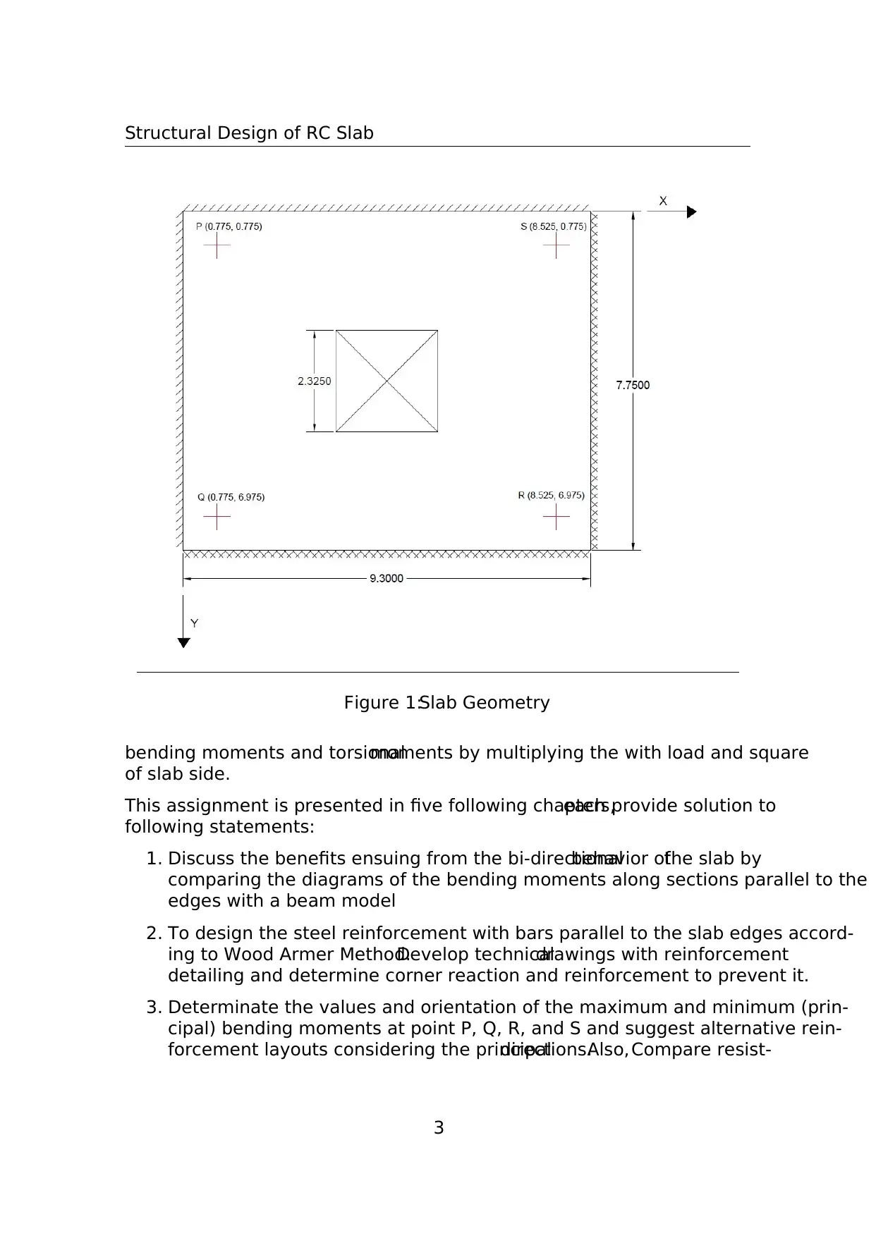
This project presents a comprehensive structural design of a reinforced concrete (RC) slab with a central opening, adhering to the standards of Politecnico Di Milano's Advanced Structural Design course. The assignment begins with an overview of the slab's geometry, loading conditions, and material properties, including concrete class C25/30 and reinforcing steel B450C. The core of the project involves comparing the slab's behavior to a beam model to highlight its bi-directional characteristics. The steel reinforcement is then designed using the Wood-Armer method, encompassing the calculation of bending and torsional moments to determine the required reinforcement areas for both bottom and top layers. The project further investigates the principal bending moments at various points and suggests alternative reinforcement layouts. Yield line theory is employed to assess the collapse load, and the strip method is explored to identify potential improvements in reinforcement design, discussing the distinctive features of limit analysis. Technical drawings with reinforcement detailing and corner reaction calculations are also provided. The project covers key aspects of structural analysis and design, including bending moments, torsional moments, the Wood-Armer method, yield line analysis, reinforcement detailing, and the impact of openings on slab behavior.
Document Page
Politecnico Di Milano
Advanced Structural Design
Prof. Fabio Biondini
Structural Design of RC Slab
Authors:
Gupta Shashank
Patil Swaraj
Enrolment Number:
918858
915621
November 16, 2018
tabler-icon-diamond-filled.svg

Paraphrase This Document

Need a fresh take? Get an instant paraphrase of this document with our AI Paraphraser
Document Page
Structural Design of RC Slab
Contents
1 Overview of Slab 2
2 Comparison of Slab and Beam model 6
3 Steel Reinforcement Design by Wood-Armer
Method 12
4 Principal Bending Moments 33
5 Yield Line Analysis 42
6 Strip Method Design of Slab reinforcement 54
1
Document Page
Structural Design of RC Slab
1 Overview of Slab
The objective of this assignment is to design and analyse the reinforcement of con-
crete slab with an central opening.
The reinforced slab is clamped on two adjacent edges and simply supported on the
others, as shown in Figure 1.The slab is to be designed at the ultimate limit state
under uniformly distributed loading.In this study, the concrete class used is C25/30
and the reinforcing steel type is B450C.
The geometrical parameters and design load are given as follows:
Slab Side, a = 6 + 1.75 = 7.75 m
Slab Depth, h ≥ a/30 ⇒ h ≥ 258.3 mm.Hence, h = 260 mm
Self Weight, gok = γ ∗ h = 6.5kN/m2
Weight of non-structural Components, g1k = 1kN/m2
Permanent Load, gk = gok + g1k = 7.5kN/m2
Live load, qk = 4kN/m2 [Recommended for D1 category of use, Table 6.2, EC1]
Safety Factors, γg = 1.35 and γk = 1.5
Design Load, pu = γg gk + γk qk = 16.125kN/m2
Exposure Class = XC3
Concrete Class C25/30 and reinforcing steel type B450C are used in this study.
f ck = 25 MPa
f cd = 14.1667 MPa
f ctk = 3.3 MPa
f ctd = 1.76 MPa
cu = 0.0035
f yk = 450 MPa
f yd = 391.304 MPa
yd = 0.00196
Es = 200000 MPa
The bending moments Mxu, Myu and the torsional moment Mxyu, computed under
uniform load pu, are given in dimensionless form.Figure 2-4 shows the calculated
2
Document Page
Structural Design of RC Slab
Figure 1:Slab Geometry
bending moments and torsionalmoments by multiplying the with load and square
of slab side.
This assignment is presented in five following chapters,each provide solution to
following statements:
1. Discuss the benefits ensuing from the bi-directionalbehavior ofthe slab by
comparing the diagrams of the bending moments along sections parallel to the
edges with a beam model
2. To design the steel reinforcement with bars parallel to the slab edges accord-
ing to Wood Armer Method.Develop technicaldrawings with reinforcement
detailing and determine corner reaction and reinforcement to prevent it.
3. Determinate the values and orientation of the maximum and minimum (prin-
cipal) bending moments at point P, Q, R, and S and suggest alternative rein-
forcement layouts considering the principaldirections.Also, Compare resist-
3
tabler-icon-diamond-filled.svg

Paraphrase This Document

Need a fresh take? Get an instant paraphrase of this document with our AI Paraphraser
Document Page
Structural Design of RC Slab
Figure 2:Bending Moment along x direction
Figure 3:Bending Moment along y direction
Figure 4:Torsional Moments
4
Document Page
Structural Design of RC Slab
ing and acting bending moments at these points versus the orientation of the
bending plane and comment on the effectiveness of the reinforcement layouts
considered.
4. Assess the collapse load of the slab reinforced with steelbars parallelto the
edges by using the yield line theory and comment on the the difference with
respect to the ultimate design load.
5. Identify possible improvements of the reinforcement design by using the strip
method and discuss the distinctive features of limit analysis applied to rein-
forced concrete slabs.
5
Document Page
Structural Design of RC Slab
2 Comparison of Slab and Beam model
In this chapter,the bending moments along the section parallelto the edges are
compared to beam model.Four sections are chosen for comparison.These sections
are shown in Figure 5.Section AA’ (ξ = 0.4) and Section BB’(η = 0.3) are sections
of highest Myu and Mxu, respectively.The comparison of the beam with these two
sections will produce an appropriate depiction.Other two sections CC’ and DD’ are
along y- and x-direction, respectively, and passes through the center of the plate.
Section AA’ and BB’ are fixed at one end and simply supported at another end.The
bending moment for similar beam can be calculated by the methods of superposition
Figure 6 shows the loading and boundary conditions of Section AA’ and BB’.
Let’s select Rb as redundant then
Ra = pL − Rb and Ma = pL2/2–RbL
From force displacement relations for a cantilever beam, deflection at point B.
δb1 = pL4/8EI and δb2 = RbL 3/3EI
From compatibility conditions
δb1 = δb2
So, Rb = 3pL/8, Ra = 5pL/8 and Ma = pL2/8
From the reactions, Bending moment, M = p/8(5Lx − L2 4x2) is obtained.This
Moment is used for Section AA’ and BB’.
For section CC’ and DD’, we have to consider two cases as shown in Figure 7.The
first step is to calculate the stiffness of the spring.The stiffness of spring is same
as that of the center of the beam along edges of hole extended to fixed and simply
supported edges.The loading and boundary conditions of the beam are shown in
Figure 8.
Let’s use the method of superposition to calculate the deflection at the center of this
beam.
Let’s select Rb as redundant then
Ra = R − Rb and Ma = RL/2–RbL
From force displacement relations for a cantilever beam, deflection at point B.
δb1 = 5RL3/48EI and δb2 = RbL 3/3EI
From compatibility conditions
δb1 = δb2
6
tabler-icon-diamond-filled.svg

Paraphrase This Document

Need a fresh take? Get an instant paraphrase of this document with our AI Paraphraser
Document Page
Structural Design of RC Slab
Figure 5:Sections for comparison
Figure 6:Loading and Boundary Conditions of Section AA’ and BB’
Figure 7:Loading and Boundary Conditions of Section CC’ and DD’
7
Document Page
Structural Design of RC Slab
Figure 8:Loading and Boundary Conditions of Spring Member
So, Rb = 15R/48, Ra = 33R/48 and Ma = 3RL/16
From deflection-moment relation and satisfying the boundary conditions,
δ = Rax3/6 − Max2/2
After substituting Ra, Ma, and x = L/2, we get δ = 7RL3/768EI
So, Stiffness is, k = 768EI/7L3
For section CC’ and DD’, let 1st case is beam with a cantilever and spring supports.
The length of the beam is L/2 and stiffness of spring is k.Let’s solve this problem
with moment-area method.
Let’s take R as redundant then,
Using moment area theorem, the deflection of the free end of the beam is as follow,
δb1 = pL4
o/8EI − RL 3
o/3EI
Downward deflection of the beam, δb2 = R/k
From compatibility conditions
δb1 = δb2
R = pL4
o
8(L 3
o
3 + 7L3
768)
8
Document Page
Structural Design of RC Slab
Figure 9:Bending Moment Comparison at Section AA’
where L = Length of beam
L o = Length of the beam along the edge of hole
For beam CC’: L = 9.3m and Lo = (7.75 2.325)/2 = 2.7 m ; R = 0.478p;
For beam DD’: L = 7.75m and Lo = (9.3 2.325)/2 = 3.48 m; R = 1.006p
The calculation ofR makes the 1st part ofSection CC’and DD’ as a cantilever
beam with a concentrated load and distributed load.BMD for such beams can be
easily constructed.The 2nd case of section CC’ and DD’ is simply supported beam
(with the assumption of small deflections).
It is worthwhile to mention,that Moment per meter are compared in the final
drawings.The loads in beam sections were not multiplied by the thickness of the
beam as the Moments in the slabs are given in kNm/m.Therefore,the bending
moments calculated in this section have units, kNm/m.
Conclusion:
In this section, considering the slab as the assembly of beams,the bending moments
of beam are compared with the given bending moments ofslab along x-and y-
directions.It can be observed that the bending moments of beams in Section AA’
and BB’ are dominant in both positive and negative moment sections.This is
an important observation because this underlines the benefits ensuing from a bi-
9
tabler-icon-diamond-filled.svg

Paraphrase This Document

Need a fresh take? Get an instant paraphrase of this document with our AI Paraphraser
Document Page
Structural Design of RC Slab
Figure 10:Bending Moment Comparison at Section BB’
Figure 11:Bending Moment Comparison at Section CC’
10
Document Page
Structural Design of RC Slab
Figure 12:Bending Moment Comparison at Section DD’
directional behavior of the slab.In fact the maximum bending moment in beams is
larger than in plates and this is due to the interaction with the twisting moment,
which has a non zero effect in slabs.It is also observed in the beams along the hole
regions i.e.Section CC’ and DD’, has lower maximum negative moments than slabs.
Similarly,in section CC’,the maximum positive bending moment of slab is higher
than beam.This shows that a presence of opening in a slab diminishes it’s bi-axial
behaviour.
11
chevron_up_icon
1 out of 70
circle_padding
hide_on_mobile
zoom_out_icon
[object Object]