Case Study Analysis: Heat Exchanger and Drilling Tool Failures
VerifiedAdded on 2022/08/27
|18
|3724
|33
Case Study
AI Summary
This coursework presents three case studies focusing on the failure analysis of mechanical components. The first case study examines the failure of heat exchanger tubes, identifying fabrication errors, thermal expansion, and poor workmanship as potential causes. The second case study investigates the fracture of a martensitic microstructure in a low alloy steel drilling tool, attributing the failure to environmentally assisted fatigue and non-uniform mechanical properties. The third case study analyzes the failure of dissimilar metallic alloys (mild steel and austenitic stainless steel) joined in an offshore environment, highlighting corrosion and cracking issues in the welded joint. Additionally, the coursework includes the determination of da/dN and K values using the Walker Equation for a 7075-T6 aluminum plate and a discussion of the Kth and Kic values based on Linear Elastic Fracture Mechanics.
Running head: COURSEWORK TWO - CASE STUDY 1
Coursework Two - Case Study
Institutional affiliation
First name Last name
Coursework Two - Case Study
Institutional affiliation
First name Last name
Paraphrase This Document
Need a fresh take? Get an instant paraphrase of this document with our AI Paraphraser
COURSEWORK TWO - CASE STUDY 2
Coursework Two - Case Study
Case Study One- Failed Heat Exchanger Tube
Fabrication methods that are used in joining the parts of the heat exchanger has
significant effect on its susceptibility to cracking which may be due to corrosion or high
temperatures. Precautions must be undertaken prior to the installation to ensure that the welded
joints in the heat exchanger tubes can withstand the temperatures and corrosion transportation in
the working environments of the component. Tests such as the dye-penetrant tests on the welded
joints after rolling and heat treatment including hydro-tests are among the precautionary
measures required for the heat exchanger tubes. However, studies have shown that cracks
develop or propagate in different stages, including stages I, II and II, therefore the development
and subsequent detection of the over the six months of the operation (Wang, 2018). Also,
temperature above the material coupled with frequent expansion and contraction cause fatigue
reduction and degradation of the welded joint and subsequent fracture. Generally, it is important
that the failed piece is removed from operation and presented from inspection and repair thus
avoiding poisoning of both the products and operators due to inefficiencies in the heat exchanger
tubes.
The failed exchanger tubes are essentially made of austenitic stainless steel, the
chromium-carbon alloy that is characterised by a structure of martensitic crystals when hardened
(Eghlimi, 2015). Looking at the provided microscopic images, it evident that there are cracks on
the surface which are at advanced stage of propagation.
COURSEWORK TWO - CASE STUDY 3
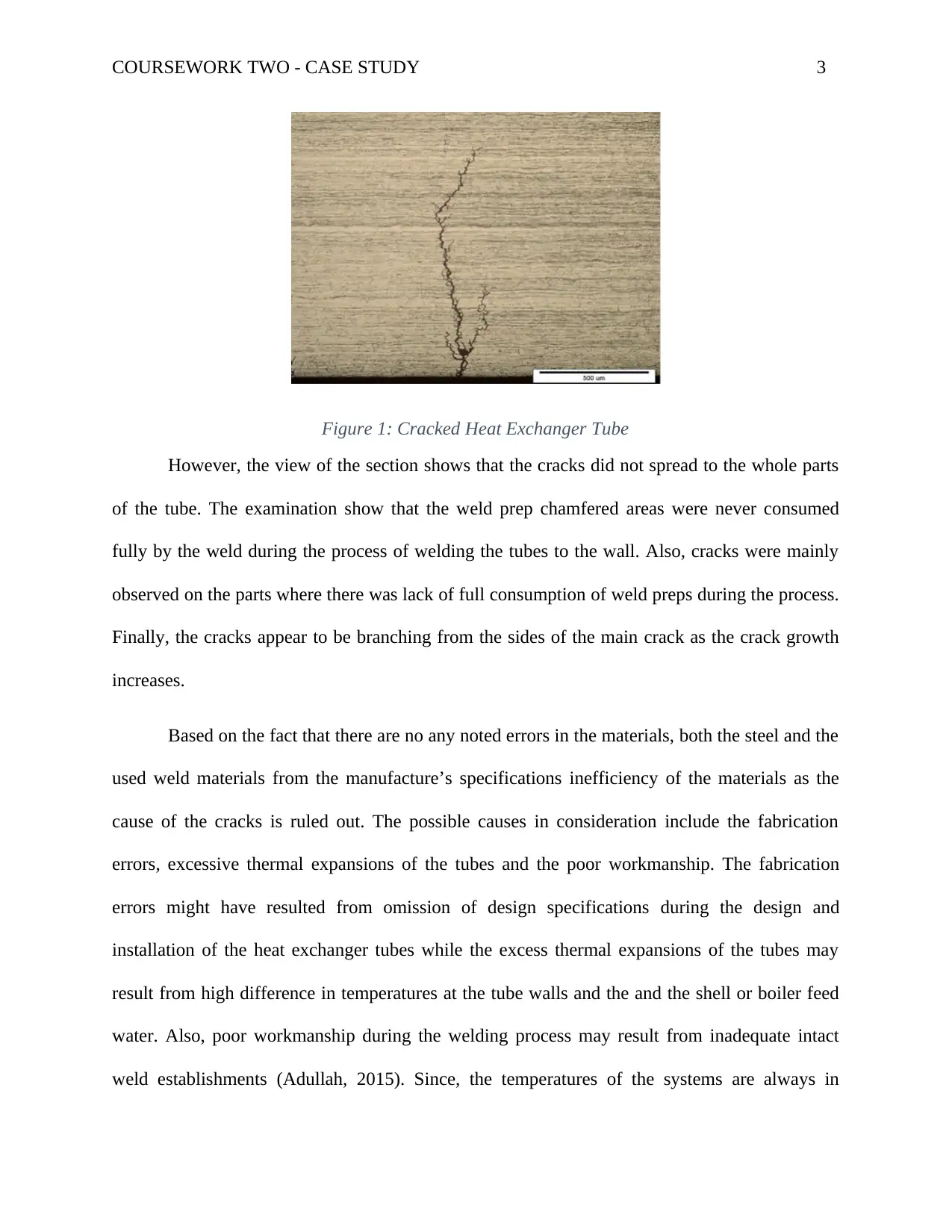
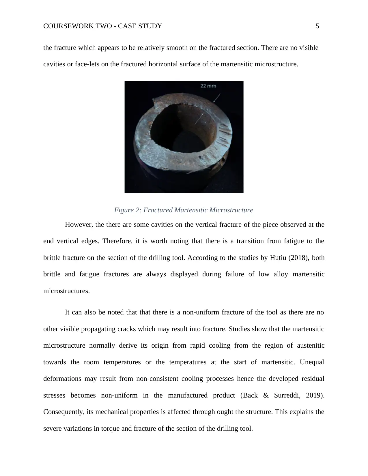
Figure 1: Cracked Heat Exchanger Tube
However, the view of the section shows that the cracks did not spread to the whole parts
of the tube. The examination show that the weld prep chamfered areas were never consumed
fully by the weld during the process of welding the tubes to the wall. Also, cracks were mainly
observed on the parts where there was lack of full consumption of weld preps during the process.
Finally, the cracks appear to be branching from the sides of the main crack as the crack growth
increases.
Based on the fact that there are no any noted errors in the materials, both the steel and the
used weld materials from the manufacture’s specifications inefficiency of the materials as the
cause of the cracks is ruled out. The possible causes in consideration include the fabrication
errors, excessive thermal expansions of the tubes and the poor workmanship. The fabrication
errors might have resulted from omission of design specifications during the design and
installation of the heat exchanger tubes while the excess thermal expansions of the tubes may
result from high difference in temperatures at the tube walls and the and the shell or boiler feed
water. Also, poor workmanship during the welding process may result from inadequate intact
weld establishments (Adullah, 2015). Since, the temperatures of the systems are always in
⊘ This is a preview!⊘
Do you want full access?
Subscribe today to unlock all pages.
Trusted by 1+ million students worldwide
COURSEWORK TWO - CASE STUDY 4
control and strict following of design specifications, establishment of inadequate welds stands
out to be the main root cause of the cracks.
The possible solutions to the problem include the removal of exchanger tube welds
through the machine process. Adequate welds should then be designed and used. It is important
that adequate tests be conducted on the tubes after machining to ascertain that there are no cracks
developed. Also, post-weld treatment should be carried out before the installation of the repaired
piece back to the system.
Case Study Two – The Fractured Martensitic Microstructure of Low Alloy Steel
Oil exploration activities require tools that are characterised by high resistance corrosion
cracking and higher fatigue life. To ensure such properties, it is important that that hardening
processes are put in place during the manufacturing such that both the external and internal
diameters are provided with adequate residual compressive stresses. Looking at low alloyed steel
AISI/SAE 4330V making the drilling tool, the material is of high strength adequate for drilling
due its high hardening and tensile strengths. It is worth noting that the tool was inefficient in its
operation prior to its failure, meaning that its servicing conditions were not adequate as it
approached its design period. It is evident from the description that the cracks on the drilling tool
had propagated to the final stage leading to its fracture and permanent failure of the piece. This
means that tool cannot be repaired for use in future to the server torque variations and fracture of
the steel.
The microstructure examination of the failed tool reveals the fracture on its edge towards
the external diameter. It can be seen that there was a straight crack path that eventually lead to
Paraphrase This Document
Need a fresh take? Get an instant paraphrase of this document with our AI Paraphraser
COURSEWORK TWO - CASE STUDY 5
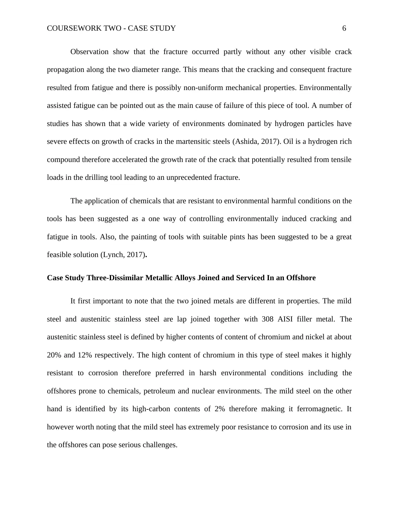
the fracture which appears to be relatively smooth on the fractured section. There are no visible
cavities or face-lets on the fractured horizontal surface of the martensitic microstructure.
Figure 2: Fractured Martensitic Microstructure
However, the there are some cavities on the vertical fracture of the piece observed at the
end vertical edges. Therefore, it is worth noting that there is a transition from fatigue to the
brittle fracture on the section of the drilling tool. According to the studies by Hutiu (2018), both
brittle and fatigue fractures are always displayed during failure of low alloy martensitic
microstructures.
It can also be noted that that there is a non-uniform fracture of the tool as there are no
other visible propagating cracks which may result into fracture. Studies show that the martensitic
microstructure normally derive its origin from rapid cooling from the region of austenitic
towards the room temperatures or the temperatures at the start of martensitic. Unequal
deformations may result from non-consistent cooling processes hence the developed residual
stresses becomes non-uniform in the manufactured product (Back & Surreddi, 2019).
Consequently, its mechanical properties is affected through ought the structure. This explains the
severe variations in torque and fracture of the section of the drilling tool.
COURSEWORK TWO - CASE STUDY 6
Observation show that the fracture occurred partly without any other visible crack
propagation along the two diameter range. This means that the cracking and consequent fracture
resulted from fatigue and there is possibly non-uniform mechanical properties. Environmentally
assisted fatigue can be pointed out as the main cause of failure of this piece of tool. A number of
studies has shown that a wide variety of environments dominated by hydrogen particles have
severe effects on growth of cracks in the martensitic steels (Ashida, 2017). Oil is a hydrogen rich
compound therefore accelerated the growth rate of the crack that potentially resulted from tensile
loads in the drilling tool leading to an unprecedented fracture.
The application of chemicals that are resistant to environmental harmful conditions on the
tools has been suggested as a one way of controlling environmentally induced cracking and
fatigue in tools. Also, the painting of tools with suitable pints has been suggested to be a great
feasible solution (Lynch, 2017).
Case Study Three-Dissimilar Metallic Alloys Joined and Serviced In an Offshore
It first important to note that the two joined metals are different in properties. The mild
steel and austenitic stainless steel are lap joined together with 308 AISI filler metal. The
austenitic stainless steel is defined by higher contents of content of chromium and nickel at about
20% and 12% respectively. The high content of chromium in this type of steel makes it highly
resistant to corrosion therefore preferred in harsh environmental conditions including the
offshores prone to chemicals, petroleum and nuclear environments. The mild steel on the other
hand is identified by its high-carbon contents of 2% therefore making it ferromagnetic. It
however worth noting that the mild steel has extremely poor resistance to corrosion and its use in
the offshores can pose serious challenges.
⊘ This is a preview!⊘
Do you want full access?
Subscribe today to unlock all pages.
Trusted by 1+ million students worldwide
COURSEWORK TWO - CASE STUDY 7
Welding of both the mild steel and austenitic stainless steel brings about challenges
during the process especially when the arc welding is used. The problem of hot cracking is the
main problem during the welding of the austenitic stainless steel with mild steel. However, this is
reduced or solved by the use of the filler metal like the 308 AISI. Also, Tungsten Inert Gas is
applied in the welding of the two parts together. According to Baghel & Nagesh (2016), TIG
welding is appropriate for use in joining mild steel and austenitic stainless steel as the
development of the cracks during the welding process is significantly eliminated.
The microscopic examination identifies two problems that are likely to be experienced by
this piece in relation to the environment under consideration. It is known that mild steel is highly
susceptible to the corrosive environments such as the offshores that are typically characterised by
salty-humid conditions (Steel, 2019). This will result into fast corrosion of the mild steel and
extended into the destruction of the welded joint through corrosion. The corrosion is likely to
cause and propagate cracks on the joint with the end result being the fracture and the separation
of the two joined metals. There are a number of options to be considered for solution to the
corrosion, cracking and failure of the welded joint. Coating of the mild steel through different
methods like painting is a method that can be applied as a temporary solution. According to
Karthick (2018), the use of galvanization method in shielding mild steel against corrosion has
produced better results especially in the sea or offshore environments. It is therefore important to
conclude that the process of joining the two metals for providing the necessary service can be
done but the mild steel should be galvanized so as to increase the life of the component. Better
service will also be realised when galvanization is used as compared to painting even though the
method is expensive.
Paraphrase This Document
Need a fresh take? Get an instant paraphrase of this document with our AI Paraphraser
COURSEWORK TWO - CASE STUDY 8
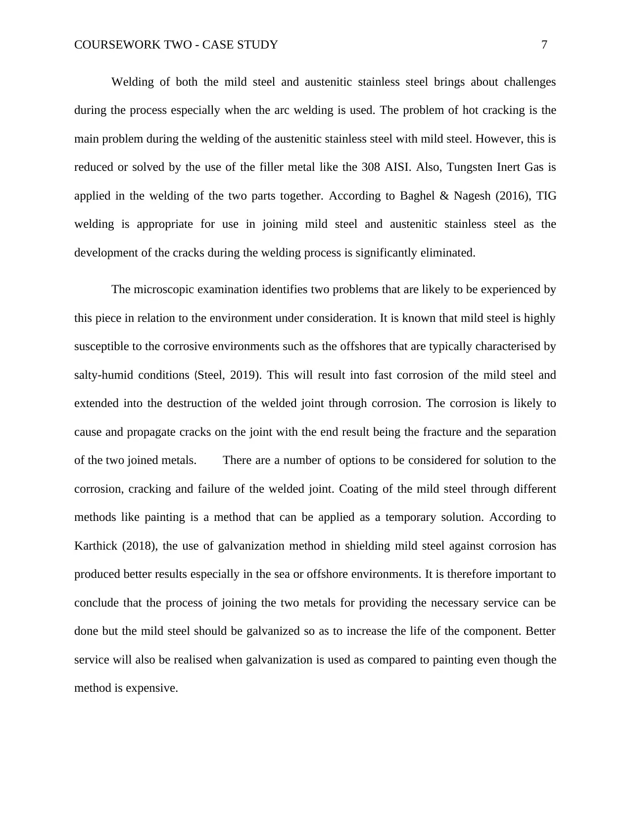
Part 2: Fracture Toughness
Having the table and curves for the Walker Equation constants for various metals.
Given that the plate is made of 7075-T6 aluminium.
The specimen dimensions:
h = 445, b = 152.4, t = 2.29 mm.
Minimum force= 10 kN
Maximum force =48 kN.
a) The determination of the da/dN and K values involves the application of Walker
Equation charts. Table 1 shows the Walker Equation chart for different types of metal
alloys.
COURSEWORK TWO - CASE STUDY 9
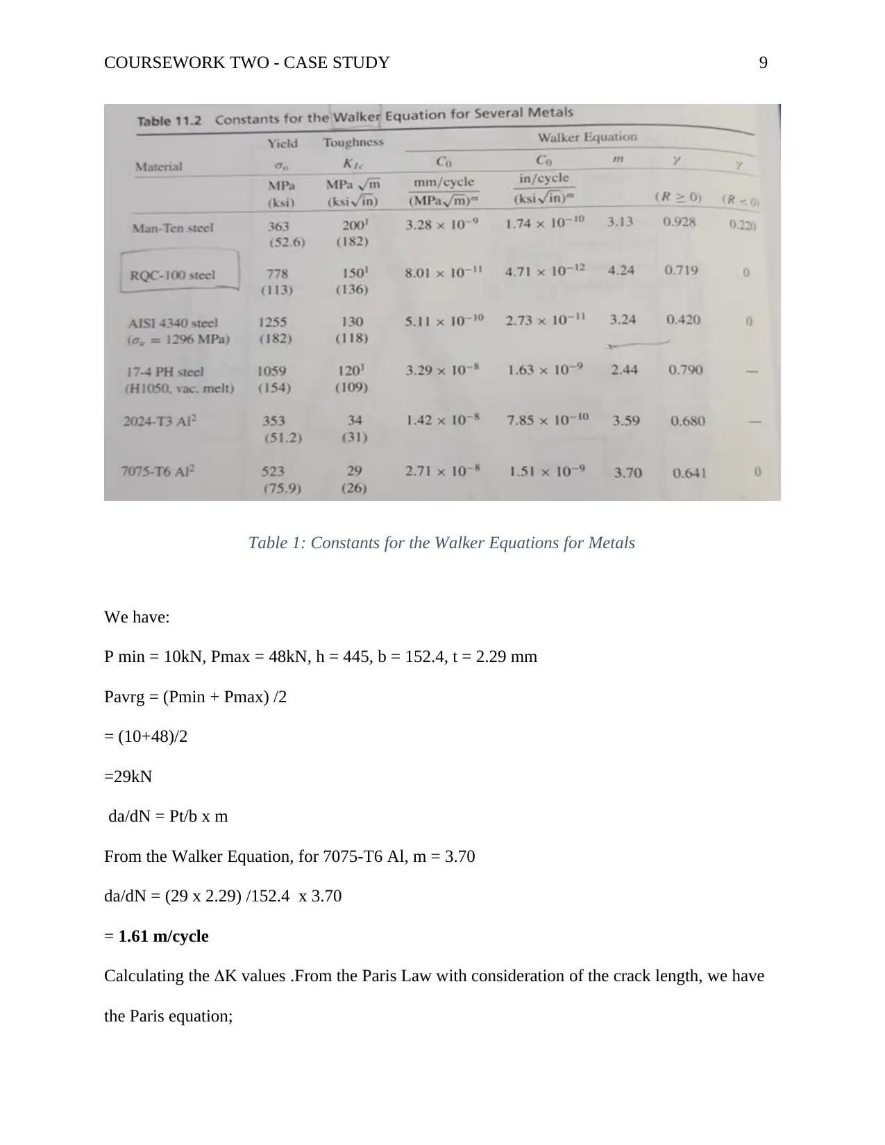
Table 1: Constants for the Walker Equations for Metals
We have:
P min = 10kN, Pmax = 48kN, h = 445, b = 152.4, t = 2.29 mm
Pavrg = (Pmin + Pmax) /2
= (10+48)/2
=29kN
da/dN = Pt/b x m
From the Walker Equation, for 7075-T6 Al, m = 3.70
da/dN = (29 x 2.29) /152.4 x 3.70
= 1.61 m/cycle
Calculating the K values .From the Paris Law with consideration of the crack length, we have
the Paris equation;
⊘ This is a preview!⊘
Do you want full access?
Subscribe today to unlock all pages.
Trusted by 1+ million students worldwide
COURSEWORK TWO - CASE STUDY 10
da /dN = c(K)m
From table 1, the crack length, A = 2.71 x 10⁻⁸, m = 3.70
1.61 = 2.71 x 10⁻⁸ x (K) ^3.70
59409594.1 = (K) ^3.70
K = 3.70√59409594.1
K = 126.2 Mpa.m0.5
b) Illustration of the Kth and KiC values on a sketched diagram.
Rice (1988), developed the Linear Elastic Fracture Mechanics which forms the basic
fracture theory for the illustration of Kth and the Kic values in a structure. According to the
theory, the propagation of crack takes place in different stages including stage 1, stage 2 and
stage 3.It is important to note that just before crack propagation stage 1, the material is in normal
working condition and there are no notable fractures on the material therefore no crack
propagation. However, the start of crack propagation is marked by the development of the crack
resistance at a value at the smallest value (Kth).This marks the stage I where the crack is just
starting to propagate with the Kth value.
As the rate of the propagation increases, the stage II of crack propagation is achieved, the
point at which the crack resistance of the material is also higher increase. Stage II is
characterised by larger cracks and crack resistance. At Stage II, the rate of crack propagation,
da/dN = c (K) m. This is a linear equation with da/dN = rate of propagation and (K) m = stress
intensity factor range.
Also, the Stage III is characterised by the fast fracture of the material. This means that the
material has achieved its high value of fracture toughness, thus the critical fracture toughness
value Kic.
Paraphrase This Document
Need a fresh take? Get an instant paraphrase of this document with our AI Paraphraser
COURSEWORK TWO - CASE STUDY 11
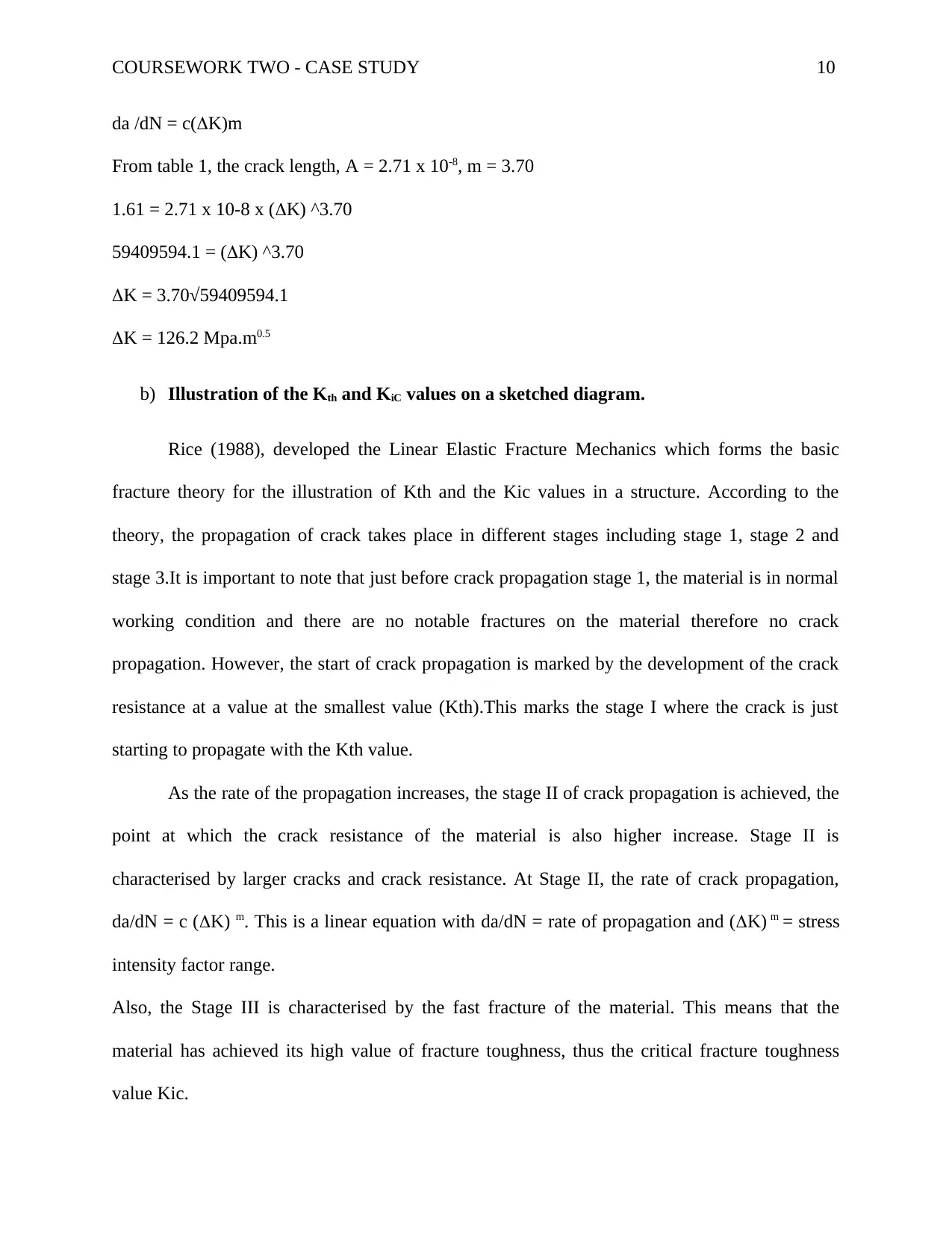
J a – mm N – cycles
1 5.08 0
2 7.62 18300
3 10.16 28300
4 12.70 35000
5 15.24 40000
6 17.78 43000
7 20.32 47000
8 22.86 50000
9 25.40 52000
10 30.48 57000
11 35.56 59000
12 40.60 61000
13 45.72 62000
Table 2: Crack Lengths and Cycles
Having the tabulated data, a graph of crack length, a-mm against cycles, N-Cycles is developed.
The slope of the curve obtained gives the growth rate of the crack (da/dN) in the aluminium
centre cracked plate.
COURSEWORK TWO - CASE STUDY 12
0 10000 20000 30000 40000 50000 60000 70000
0
5
10
15
20
25
30
35
40
45
50
a – mm
N-Cycles
a-mm
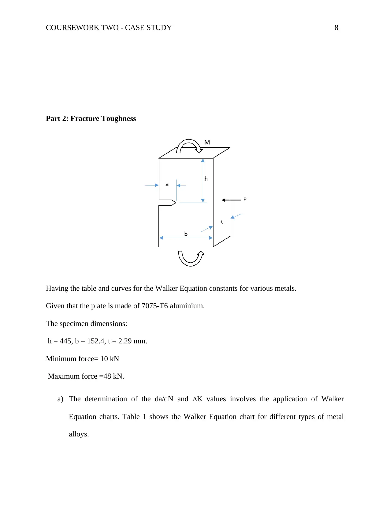
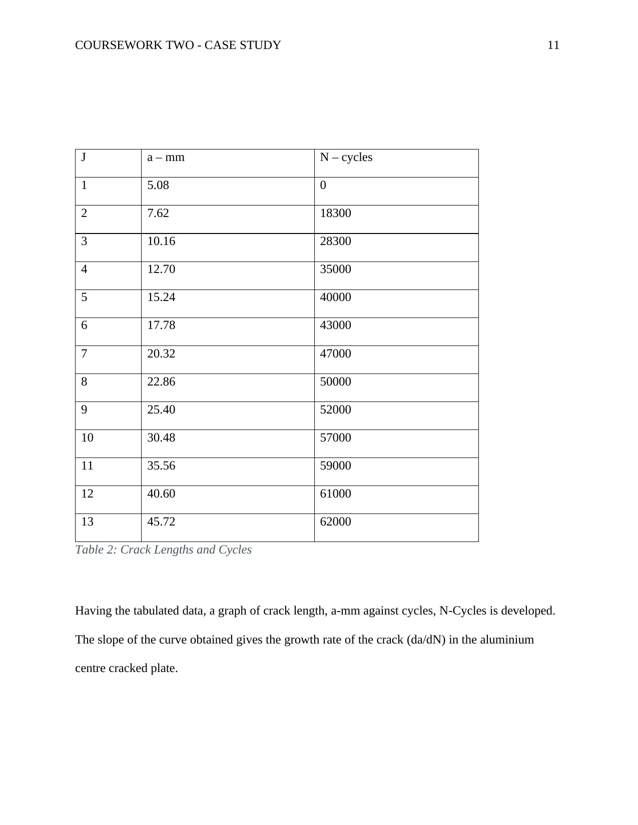
Figure 3: Graph of Crack Length against Cycles
The crack propagation or growth rates obtained from various points of the curve are then plotted
against the range of the stress intensity factor to obtain the propagation curve. Figure 4 shows a
typical propagation growth rate curve. Fracture toughness, Kic is directly proportional to the
stress and the square root of the crack length of the material. Kic α stress x constant x crack
length 0.5
Kic = δ x constant x c0.5
Mathematically, the crack propagation rate can be calculated as, da/dN = [𝑎 (j ) −𝑎 (𝑗−1)]/
[𝑁(𝑗)−𝑁(𝑗−1)].
From Paris Law da/dN = AKm, K = Kmax - Kmin
Also, assuming suitable values of stress factor range, table 3 can be developed
0 10000 20000 30000 40000 50000 60000 70000
0
5
10
15
20
25
30
35
40
45
50
a – mm
N-Cycles
a-mm
Figure 3: Graph of Crack Length against Cycles
The crack propagation or growth rates obtained from various points of the curve are then plotted
against the range of the stress intensity factor to obtain the propagation curve. Figure 4 shows a
typical propagation growth rate curve. Fracture toughness, Kic is directly proportional to the
stress and the square root of the crack length of the material. Kic α stress x constant x crack
length 0.5
Kic = δ x constant x c0.5
Mathematically, the crack propagation rate can be calculated as, da/dN = [𝑎 (j ) −𝑎 (𝑗−1)]/
[𝑁(𝑗)−𝑁(𝑗−1)].
From Paris Law da/dN = AKm, K = Kmax - Kmin
Also, assuming suitable values of stress factor range, table 3 can be developed
⊘ This is a preview!⊘
Do you want full access?
Subscribe today to unlock all pages.
Trusted by 1+ million students worldwide
1 out of 18

Your All-in-One AI-Powered Toolkit for Academic Success.
+13062052269
info@desklib.com
Available 24*7 on WhatsApp / Email
![[object Object]](/_next/static/media/star-bottom.7253800d.svg)
Unlock your academic potential
Copyright © 2020–2026 A2Z Services. All Rights Reserved. Developed and managed by ZUCOL.