Structural Principles Applied to Low Rise Commercial Construction
VerifiedAdded on 2023/06/03
|10
|1295
|112
Report
AI Summary
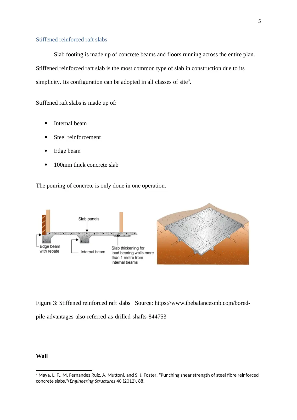
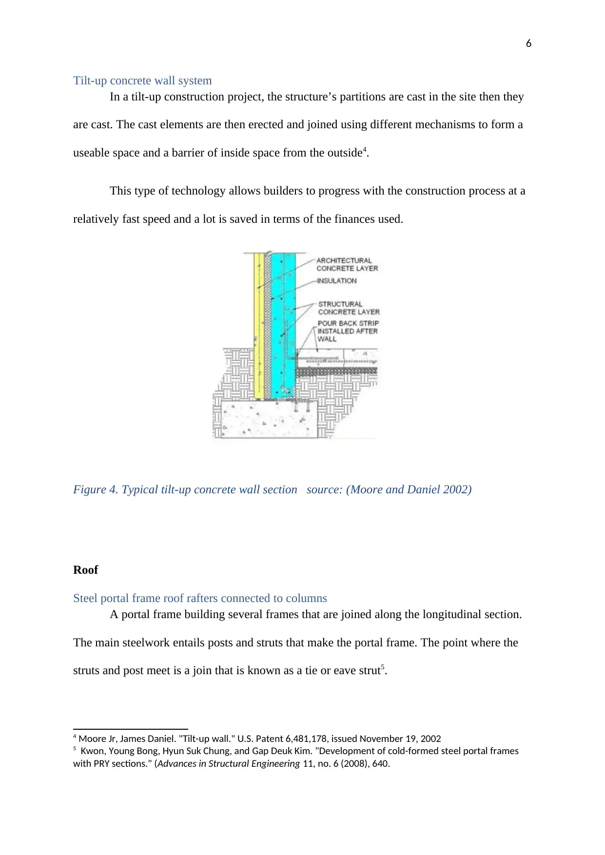
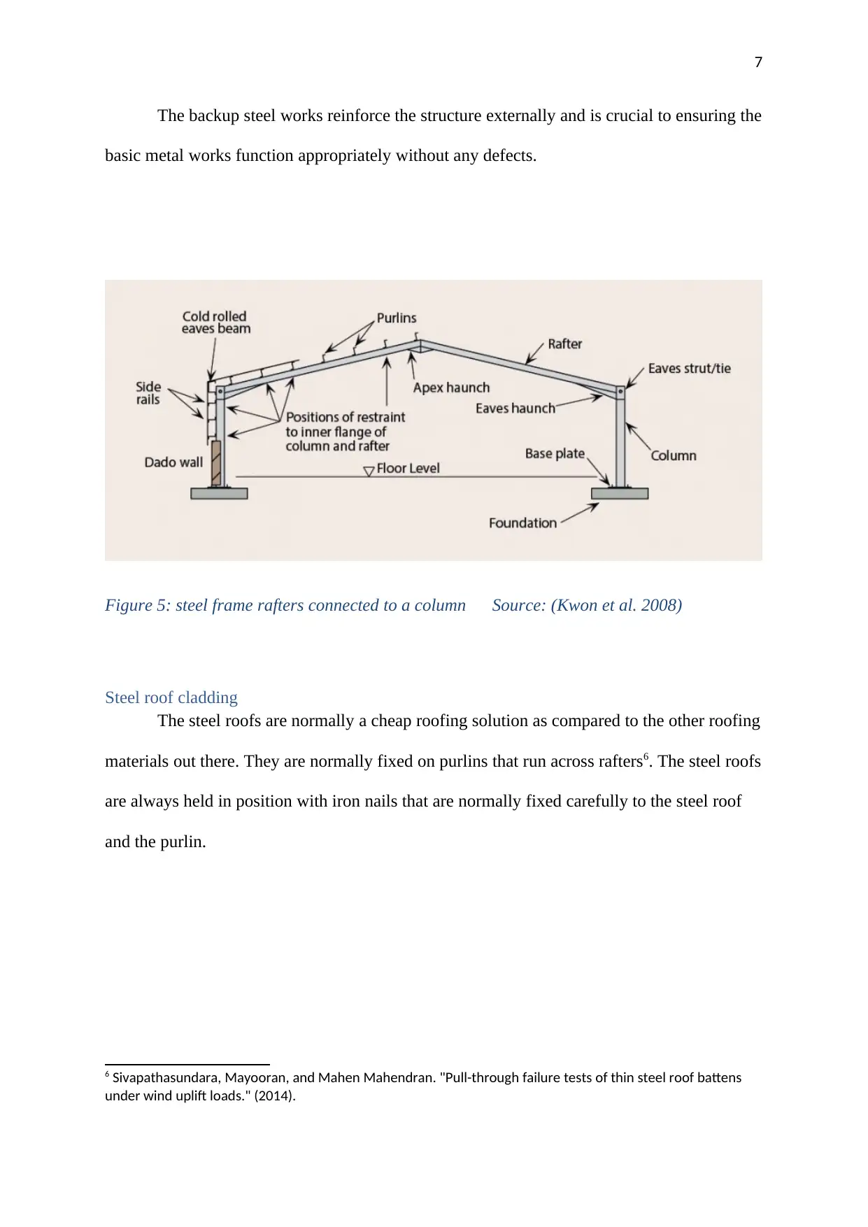
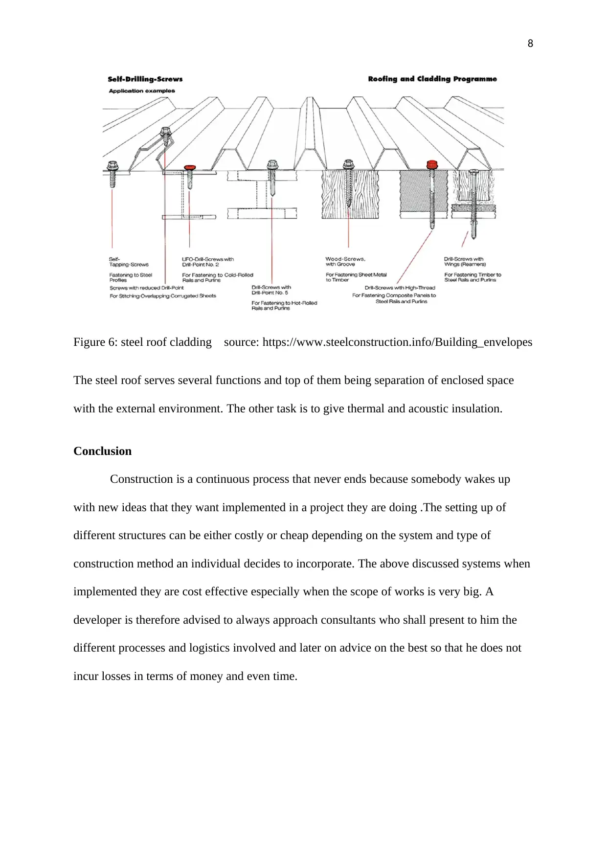
This report provides a detailed overview of structural principles applied to commercial low-rise construction. It begins by discussing different footing systems, including pier and beam footings and bored pile systems, highlighting their applications and advantages. The report then explores floor systems, focusing on stiffened reinforced raft slabs. Moving on to wall systems, the report examines tilt-up concrete wall systems, describing their construction process and benefits. Finally, the report covers roof structures, detailing steel portal frame roof rafters and steel roof cladding, emphasizing their functions and cost-effectiveness. The conclusion emphasizes the importance of considering various construction methods and consulting professionals for efficient and cost-effective project implementation. The report includes relevant figures and a bibliography of cited sources.

1
APPLY STRUCTURAL PRINCIPLES TO COMMERCIAL LOW RISE CONSTRUCTION
Student’s Name
Course Name
Date
APPLY STRUCTURAL PRINCIPLES TO COMMERCIAL LOW RISE CONSTRUCTION
Student’s Name
Course Name
Date
Paraphrase This Document
Need a fresh take? Get an instant paraphrase of this document with our AI Paraphraser

2
Table of content
Footing.......................................................................................................................................2
Pier and beam footing.............................................................................................................2
A bored pile system................................................................................................................3
Floor..........................................................................................................................................4
Stiffened reinforced raft slabs................................................................................................4
Wall............................................................................................................................................5
Tilt-up concrete wall system..................................................................................................6
Roof............................................................................................................................................6
Steel portal frame roof rafters connected to columns.............................................................6
Steel roof cladding..................................................................................................................7
Conclusion.................................................................................................................................8
References.................................................................................................................................9

3
Footing
Pier and beam footing
Footings are anchors of a pier and a beam foundation. Main materials used are
reinforced masonry, supported by reinforced concrete. It is important to ensure that the
footings are fixed below the maximum frost depth.
Pier and beam foundation is made up of concrete footing and the piers main function
is to support the structures and the floor joist. In most cases, these foundation leaves a
ventilation space underneath the floor depending on the slope of the land upon which the
building is built. The piers spacing mainly depends on the arrangement of floor span framing
especially where the load bearing walls and partitions are located. Pier spacing in most cases
have a range of 8 – 10’1.
Figure 1: Pier and beam footing source:
https://www.steelconstruction.info/Building_envelopes
1 Civil Construction Tips. 2010. Short bored pile foundation. December 4. Accessed November 2, 2018.
http://civilconstructiontips.blogspot.com/2011/06/short-bored-pile-foundation.html.
⊘ This is a preview!⊘
Do you want full access?
Subscribe today to unlock all pages.

Trusted by 1+ million students worldwide

4
A bored pile system
Bored pile system is a type of RC pile which is used in the construction of high rise
building with high parallel loads. Bore pile is normally done on site mainly referred to as
cast-in place concrete. Shafts are drilled using the bore piling machine which are designed to
drill and remove soil and rocks from the ground. It can drill up to 50m depth of soil2. This
type of pile system is advantageous because it has minimal vibration hence the noise levels
are reduced compared to the traditional piling system.
Figure 2: Drilling through a rock layer with the chisel device Source:
http://civilconstructiontips.blogspot.com/2011/06/short-bored-pile-foundation.html
Floor
2 Rodriguez, Juan. 2018. Techniques and Procedures for Bored Pile (Drilled Shafts). July 18. Accessed November
2, 2018. https://www.thebalancesmb.com/bored-pile-advantages-also-referred-as-drilled-shafts-844753.
Paraphrase This Document
Need a fresh take? Get an instant paraphrase of this document with our AI Paraphraser

5
Stiffened reinforced raft slabs
Slab footing is made up of concrete beams and floors running across the entire plan.
Stiffened reinforced raft slab is the most common type of slab in construction due to its
simplicity. Its configuration can be adopted in all classes of site3.
Stiffened raft slabs is made up of:
Internal beam
Steel reinforcement
Edge beam
100mm thick concrete slab
The pouring of concrete is only done in one operation.
Figure 3: Stiffened reinforced raft slabs Source: https://www.thebalancesmb.com/bored-
pile-advantages-also-referred-as-drilled-shafts-844753
Wall
3 Maya, L. F., M. Fernandez Ruiz, A. Muttoni, and S. J. Foster. "Punching shear strength of steel fibre reinforced
concrete slabs."(Engineering Structures 40 (2012), 88.

6
Tilt-up concrete wall system
In a tilt-up construction project, the structure’s partitions are cast in the site then they
are cast. The cast elements are then erected and joined using different mechanisms to form a
useable space and a barrier of inside space from the outside4.
This type of technology allows builders to progress with the construction process at a
relatively fast speed and a lot is saved in terms of the finances used.
Figure 4. Typical tilt-up concrete wall section source: (Moore and Daniel 2002)
Roof
Steel portal frame roof rafters connected to columns
A portal frame building several frames that are joined along the longitudinal section.
The main steelwork entails posts and struts that make the portal frame. The point where the
struts and post meet is a join that is known as a tie or eave strut5.
4 Moore Jr, James Daniel. "Tilt-up wall." U.S. Patent 6,481,178, issued November 19, 2002
5 Kwon, Young Bong, Hyun Suk Chung, and Gap Deuk Kim. "Development of cold-formed steel portal frames
with PRY sections." (Advances in Structural Engineering 11, no. 6 (2008), 640.
⊘ This is a preview!⊘
Do you want full access?
Subscribe today to unlock all pages.

Trusted by 1+ million students worldwide

7
The backup steel works reinforce the structure externally and is crucial to ensuring the
basic metal works function appropriately without any defects.
Figure 5: steel frame rafters connected to a column Source: (Kwon et al. 2008)
Steel roof cladding
The steel roofs are normally a cheap roofing solution as compared to the other roofing
materials out there. They are normally fixed on purlins that run across rafters6. The steel roofs
are always held in position with iron nails that are normally fixed carefully to the steel roof
and the purlin.
6 Sivapathasundara, Mayooran, and Mahen Mahendran. "Pull-through failure tests of thin steel roof battens
under wind uplift loads." (2014).
Paraphrase This Document
Need a fresh take? Get an instant paraphrase of this document with our AI Paraphraser

8
Figure 6: steel roof cladding source: https://www.steelconstruction.info/Building_envelopes
The steel roof serves several functions and top of them being separation of enclosed space
with the external environment. The other task is to give thermal and acoustic insulation.
Conclusion
Construction is a continuous process that never ends because somebody wakes up
with new ideas that they want implemented in a project they are doing .The setting up of
different structures can be either costly or cheap depending on the system and type of
construction method an individual decides to incorporate. The above discussed systems when
implemented they are cost effective especially when the scope of works is very big. A
developer is therefore advised to always approach consultants who shall present to him the
different processes and logistics involved and later on advice on the best so that he does not
incur losses in terms of money and even time.

9
Bibliography
Civil Construction Tips. 2010. Short bored pile foundation. December 4. Accessed
November 2, 2018. http://civilconstructiontips.blogspot.com/2011/06/short-bored-
pile-foundation.html.
Kwon, Young Bong, Hyun Suk Chung, and Gap Deuk Kim. "Development of cold-formed
steel portal frames with PRY sections." Advances in Structural Engineering 11, no. 6
(2008): 633-649.
Lemnitzer, Anne, Payman Khalili-Tehrani, Eric R. Ahlberg, Changsoon Rha, Ertugrul
Taciroglu, John W. Wallace, and Jonathan P. Stewart. "Nonlinear efficiency of bored
pile group under lateral loading." Journal of geotechnical and geoenvironmental
engineering 136, no. 12 (2010): 1673-1685.
Maya, L. F., M. Fernández Ruiz, A. Muttoni, and S. J. Foster. "Punching shear strength of
steel fibre reinforced concrete slabs." Engineering Structures 40 (2012): 83-94.
Rodriguez, Juan. 2018. Techniques and Procedures for Bored Pile (Drilled Shafts). July 18.
Accessed November 2, 2018. https://www.thebalancesmb.com/bored-pile-advantages-
also-referred-as-drilled-shafts-844753.
Stuedlein, Armin W., and Robert D. Holtz. "Analysis of footing load tests on aggregate pier
reinforced clay." Journal of Geotechnical and Geoenvironmental Engineering 138,
no. 9 (2011): 1091-1103.
Sivapathasundara, Mayooran, and Mahen Mahendran. "Pull-through failure tests of thin steel
roof battens under wind uplift loads." (2014).
⊘ This is a preview!⊘
Do you want full access?
Subscribe today to unlock all pages.

Trusted by 1+ million students worldwide

10
1 out of 10