Structures 1 Group Coursework: Mechanical Systems Analysis Report
VerifiedAdded on 2023/06/15
|20
|1792
|324
Report
AI Summary
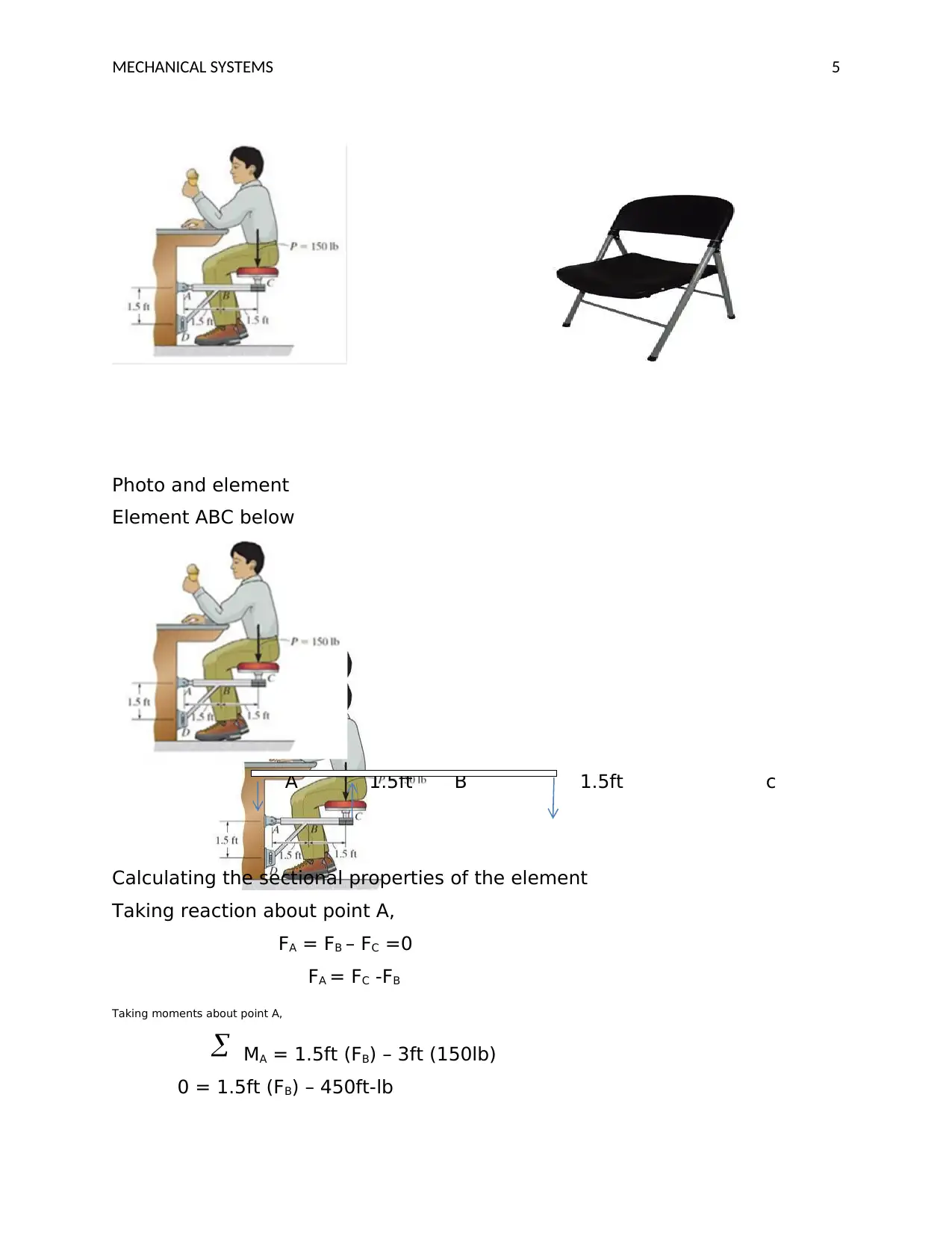
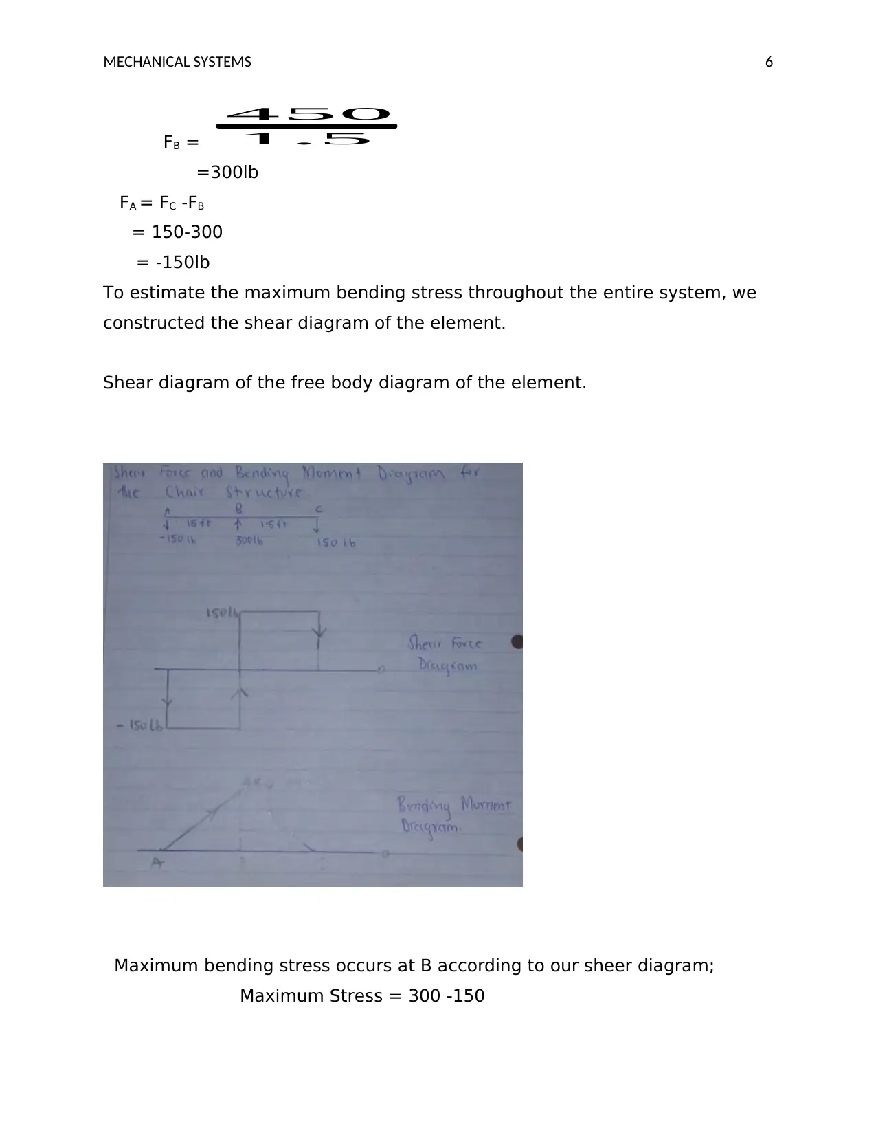
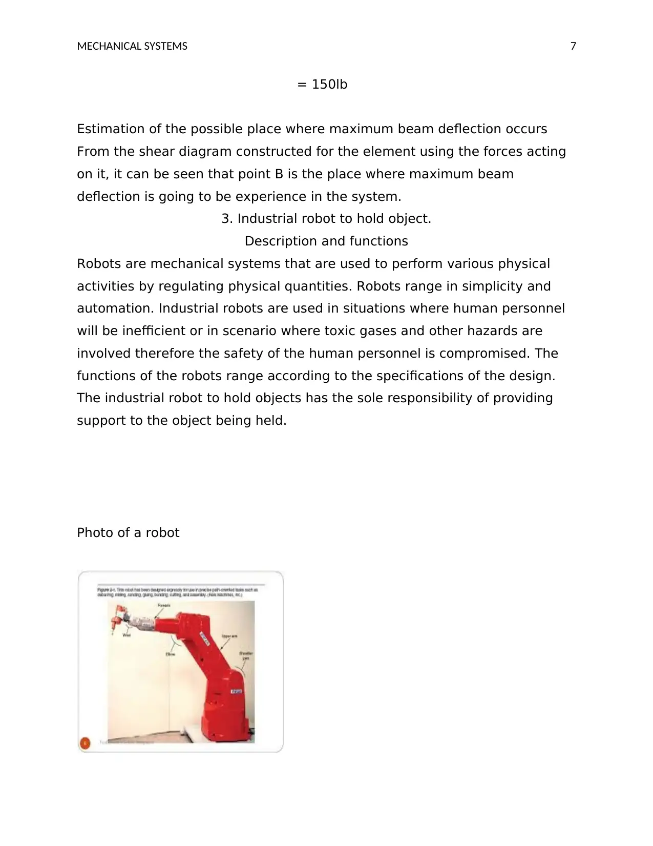
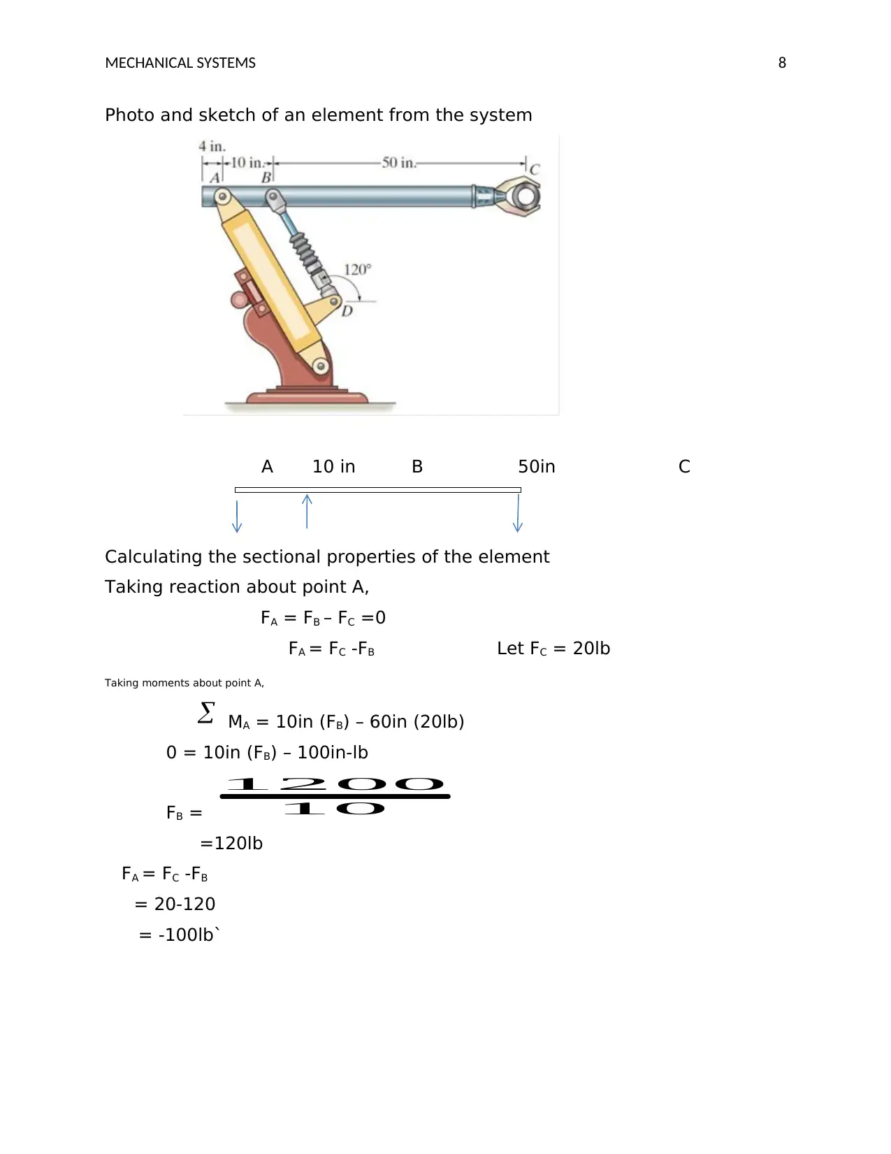
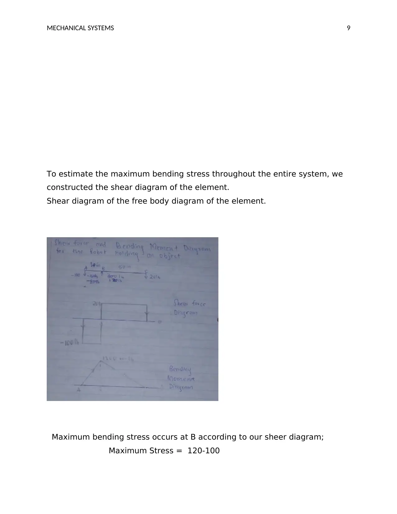
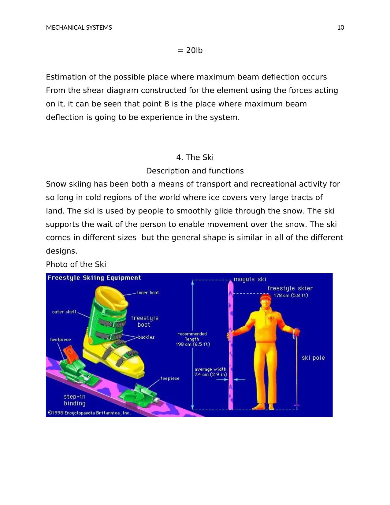
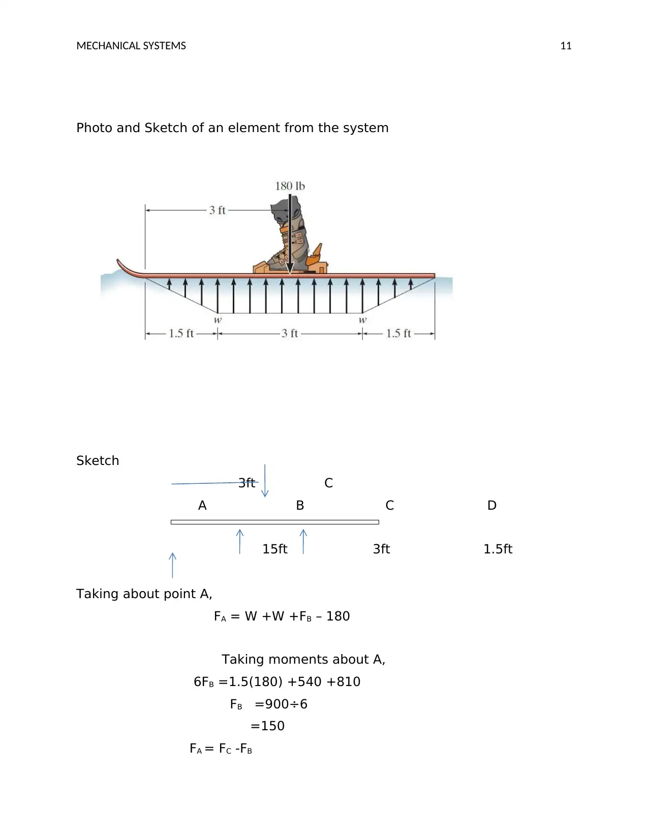
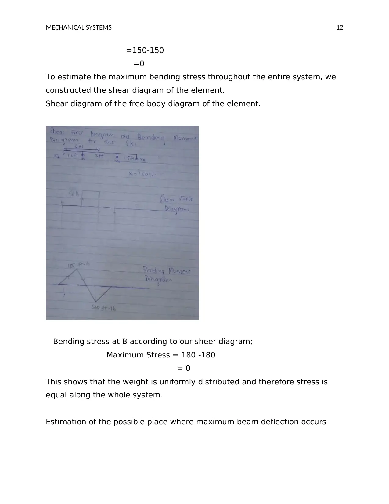
This report presents a structural analysis of various real-world mechanical systems, linking the concepts taught in Structures 1 to practical applications. The study identifies suitable elements subjected to bending from systems like engine cranes, chairs, industrial robots, skis, signposts, and diving boards. For each element, the report includes sketches with estimated dimensions, photographs, estimations of external loads, shear force diagrams, bending moment diagrams, and calculations of sectional properties. The maximum bending stress and the location of maximum beam deflection are estimated for each element. The analysis assumes rigid parts and equilibrium conditions, highlighting the importance of these calculations for design processes and material selection. The report concludes with a summary of the coursework and reflections on the collaborative effort of the group members.

Running head: MECHANICAL SYSTEMS 1
Mechanical Systems
Name
Institution Affiliation
1. ENGINE CRANE.
.Description and functions
The engine crane is a familiar tool that is used to remove or install
diesel engines and gasoline engines in crowded and small vehicle
compartments. This mechanical structure is commonly found in
repair workshops and sometimes it is known as engine hoist.
Photo of the engine crane
Paraphrase This Document
Need a fresh take? Get an instant paraphrase of this document with our AI Paraphraser

MECHANICAL SYSTEMS 2
Photo and sketches of an element from the engine crane
Element ABC selected from the crane engine
A 3ft B 5ft C
Calculating the sectional property of the element
A 3ft B 5ft C
Photo and sketches of an element from the engine crane
Element ABC selected from the crane engine
A 3ft B 5ft C
Calculating the sectional property of the element
A 3ft B 5ft C

MECHANICAL SYSTEMS 3
200lb
Taking reaction about point A;
FA = FB – FC =0
FA = FC -FB
Taking the moments about point A;
MA = 3ft (FB) – 8ft (200lb)
0 = 3ft (FB) – 1600ft-lb
FB = 3
1600
=533.33lb
FA = FC -FB
= 200-533.33
=- 333.33lb
Estimate of the maximum bending stress throughout the element
To estimate the maximum bending stress throughout the entire system, we
constructed the shear diagram of the element.
⊘ This is a preview!⊘
Do you want full access?
Subscribe today to unlock all pages.

Trusted by 1+ million students worldwide

MECHANICAL SYSTEMS 4
Maximum bending stress occurs at B according to our sheer diagram;
Maximum Stress = -333.33 -200
= 533.33 lb
Estimate the possible place where maximum beam deflection occurs.
From the shear diagram constructed for the element using the forces acting
on it, it can be seen that point B is the place where maximum beam
deflection is going to be experience in the system.
2. The Chair Structure.
Description and functions
A chair is simple mechanical structure that is designed for people to seat on
it and is used all over the word. There are various types of chairs in the
universe. The main function of the chair is to provide support to the
individual(s) seating on it.
Photos of a chair
Paraphrase This Document
Need a fresh take? Get an instant paraphrase of this document with our AI Paraphraser

MECHANICAL SYSTEMS 5
Photo and element
Element ABC below
A 1.5ft B 1.5ft c
Calculating the sectional properties of the element
Taking reaction about point A,
FA = FB – FC =0
FA = FC -FB
Taking moments about point A,
MA = 1.5ft (FB) – 3ft (150lb)
0 = 1.5ft (FB) – 450ft-lb
Photo and element
Element ABC below
A 1.5ft B 1.5ft c
Calculating the sectional properties of the element
Taking reaction about point A,
FA = FB – FC =0
FA = FC -FB
Taking moments about point A,
MA = 1.5ft (FB) – 3ft (150lb)
0 = 1.5ft (FB) – 450ft-lb

MECHANICAL SYSTEMS 6
FB = 5.1
450
=300lb
FA = FC -FB
= 150-300
= -150lb
To estimate the maximum bending stress throughout the entire system, we
constructed the shear diagram of the element.
Shear diagram of the free body diagram of the element.
Maximum bending stress occurs at B according to our sheer diagram;
Maximum Stress = 300 -150
⊘ This is a preview!⊘
Do you want full access?
Subscribe today to unlock all pages.

Trusted by 1+ million students worldwide

MECHANICAL SYSTEMS 7
= 150lb
Estimation of the possible place where maximum beam deflection occurs
From the shear diagram constructed for the element using the forces acting
on it, it can be seen that point B is the place where maximum beam
deflection is going to be experience in the system.
3. Industrial robot to hold object.
Description and functions
Robots are mechanical systems that are used to perform various physical
activities by regulating physical quantities. Robots range in simplicity and
automation. Industrial robots are used in situations where human personnel
will be inefficient or in scenario where toxic gases and other hazards are
involved therefore the safety of the human personnel is compromised. The
functions of the robots range according to the specifications of the design.
The industrial robot to hold objects has the sole responsibility of providing
support to the object being held.
Photo of a robot
Paraphrase This Document
Need a fresh take? Get an instant paraphrase of this document with our AI Paraphraser

MECHANICAL SYSTEMS 8
Photo and sketch of an element from the system
A 10 in B 50in C
Calculating the sectional properties of the element
Taking reaction about point A,
FA = FB – FC =0
FA = FC -FB Let FC = 20lb
Taking moments about point A,
MA = 10in (FB) – 60in (20lb)
0 = 10in (FB) – 100in-lb
FB = 10
1200
=120lb
FA = FC -FB
= 20-120
= -100lb`

MECHANICAL SYSTEMS 9
To estimate the maximum bending stress throughout the entire system, we
constructed the shear diagram of the element.
Shear diagram of the free body diagram of the element.
Maximum bending stress occurs at B according to our sheer diagram;
Maximum Stress = 120-100
To estimate the maximum bending stress throughout the entire system, we
constructed the shear diagram of the element.
Shear diagram of the free body diagram of the element.
Maximum bending stress occurs at B according to our sheer diagram;
Maximum Stress = 120-100
⊘ This is a preview!⊘
Do you want full access?
Subscribe today to unlock all pages.

Trusted by 1+ million students worldwide

MECHANICAL SYSTEMS 10
= 20lb
Estimation of the possible place where maximum beam deflection occurs
From the shear diagram constructed for the element using the forces acting
on it, it can be seen that point B is the place where maximum beam
deflection is going to be experience in the system.
4. The Ski
Description and functions
Snow skiing has been both a means of transport and recreational activity for
so long in cold regions of the world where ice covers very large tracts of
land. The ski is used by people to smoothly glide through the snow. The ski
supports the wait of the person to enable movement over the snow. The ski
comes in different sizes but the general shape is similar in all of the different
designs.
Photo of the Ski
Paraphrase This Document
Need a fresh take? Get an instant paraphrase of this document with our AI Paraphraser

MECHANICAL SYSTEMS 11
Photo and Sketch of an element from the system
Sketch
3ft C
A B C D
15ft 3ft 1.5ft
Taking about point A,
FA = W +W +FB – 180
Taking moments about A,
6FB =1.5(180) +540 +810
FB =900÷6
=150
FA = FC -FB
Photo and Sketch of an element from the system
Sketch
3ft C
A B C D
15ft 3ft 1.5ft
Taking about point A,
FA = W +W +FB – 180
Taking moments about A,
6FB =1.5(180) +540 +810
FB =900÷6
=150
FA = FC -FB

MECHANICAL SYSTEMS 12
=150-150
=0
To estimate the maximum bending stress throughout the entire system, we
constructed the shear diagram of the element.
Shear diagram of the free body diagram of the element.
Bending stress at B according to our sheer diagram;
Maximum Stress = 180 -180
= 0
This shows that the weight is uniformly distributed and therefore stress is
equal along the whole system.
Estimation of the possible place where maximum beam deflection occurs
⊘ This is a preview!⊘
Do you want full access?
Subscribe today to unlock all pages.

Trusted by 1+ million students worldwide
1 out of 20
Your All-in-One AI-Powered Toolkit for Academic Success.
+13062052269
info@desklib.com
Available 24*7 on WhatsApp / Email
Unlock your academic potential
Copyright © 2020–2025 A2Z Services. All Rights Reserved. Developed and managed by ZUCOL.
