Design and Operation of Sustainable Systems: Heliostat Bearing Design
VerifiedAdded on 2023/01/17
|15
|2747
|42
Report
AI Summary
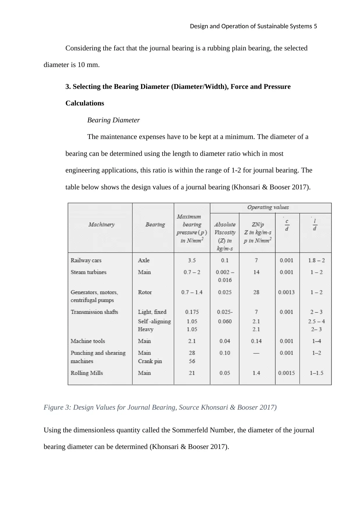
This report provides a comprehensive analysis of journal bearing design for a heliostat within a sustainable system framework. It covers bearing diameter selection using load-speed charts and Sommerfeld Number calculations, force and pressure considerations, and the determination of maximum allowable specific wear rate and PV limit. Material selection is justified based on desirable characteristics like low friction and high compressive strength, with SAE 11 Babbitt and Nylon identified as suitable options. The report also includes friction torque calculations and optimization strategies to ensure a 25-year lifespan with minimal wear. Finally, a GSM-based monitoring and prevention system is proposed to detect and report any abnormalities in heliostat operation, enhancing system reliability. The design process is iterative, optimizing for machinability and performance, ensuring a balance between theoretical calculations and practical implementation.
Contribute Materials
Your contribution can guide someone’s learning journey. Share your
documents today.

Design and Operation of Sustainable Systems 1
Design and Operation of Sustainable Systems
Name
Institutional Affiliation
Design and Operation of Sustainable Systems
Name
Institutional Affiliation
Secure Best Marks with AI Grader
Need help grading? Try our AI Grader for instant feedback on your assignments.

Design and Operation of Sustainable Systems 2
1. Introduction
Heliostat field or sun based tower collector stands out amongst the most encouraging
concentrated sun oriented power innovations accessible in the market. Because of its high
working temperature, the heliostat field collector can be actualized in a wide scope of
utilization from sun-based power generation to industrial production (Telsnig, Weinrebe,
Finkbeiner, & Eltrop 2017). There are a few as of now working, under development, and
arranged heliostat fields far and wide. There are present state-of-the-art applications,
appraisal techniques, the future point of view, and strategies for development. A focal
collector control tower framework comprises of a field of heliostats that center the daylight
onto the recipient on the tower.
Heliostats regularly comprise of a variety of mirror features that track the sun forthe day.
To achieve an optimum consideration of the solar flux on the collector, the individual
heliostat aspects must be appropriately inclined and centered. A few unique strategies have
been utilized in the past for aspect inclining and centering. These demonstrated techniques
and some new arrangement ideas are under thought for advancement and arrangement of 218
heliostats at the Sandia National Laboratories National Solar Thermal Test Facility in
Albuquerque, NM (Guillot, Rodriguez, Boullet, & Sans 2018). The precision of this
innovation is basic to guaranteeing energy reflected by the heliostats is gathered through the
liquid salt in the recipient and not "spilled" and lost. A portion of the heliostat advancement
areas incorporates deft structure plan, high accuracy, and effective drive frameworks, ultra-
light and high reflectivity features, and different heliostats and collector field control, power
and correspondence frameworks. The heliostat collector field provides a gigantic opportunity
for onsite commodity production. Remote sensing speed up collector field development and
charging, which takes out exorbitant cabling and digging. Creative heliostat plan and
arrangement is a region where noteworthy cost decrease is being acknowledged for CSP

Design and Operation of Sustainable Systems 3
ventures. Two pivot monitoring (customary azimuth) improves solar energy collection. This
paper will explore the various aspects of the journal bearing design for the heliostat.
2. Bearing Diameter Selection
Generally, a journal bearing is a journal or shaft which rotates in a bearing. There are
no rolling elements as seen in other bearings (Hase, Mishina, & Wada 2016). There is a layer
of lubricant which separates the two parts in relative motion. Selection of a diameter of a
bearing depends on the prevailing conditions and the design features of the load. For this
case, we want to select a journal bearing diameter for a heliostat. The heliostat has a mass of
300kg.
Weight = 300 × 9.81 = 2943 N
Considering the fact that the rotation of the heliostat for purposes of altering the angle
of inclination is not very rapid, it can be reasonably be assumed to be operating at 25 revs per
minute. The design is based on the requirement that the size should be big enough to last for
25 years and small enough to reduce energy loss.

Design and Operation of Sustainable Systems 4
Based on the above parameters, the diameter of the bearing can be selected from the load-
speed chart shown below in Figure 1 and Figure 2.
Figure 1: Selection by load capacity of bearings with continuous rotation. Source: Lecture Notes
Figure 2: Selection of bearing diameter using load-speed chart: Source, Lecture Notes
Secure Best Marks with AI Grader
Need help grading? Try our AI Grader for instant feedback on your assignments.

Design and Operation of Sustainable Systems 5
Considering the fact that the journal bearing is a rubbing plain bearing, the selected
diameter is 10 mm.
3. Selecting the Bearing Diameter (Diameter/Width), Force and Pressure
Calculations
Bearing Diameter
The maintenance expenses have to be kept at a minimum. The diameter of a
bearing can be determined using the length to diameter ratio which in most
engineering applications, this ratio is within the range of 1-2 for journal bearing. The
table below shows the design values of a journal bearing (Khonsari & Booser 2017).
Figure 3: Design Values for Journal Bearing, Source Khonsari & Booser 2017)
Using the dimensionless quantity called the Sommerfeld Number, the diameter of the journal
bearing diameter can be determined (Khonsari & Booser 2017).

Design and Operation of Sustainable Systems 6
In engineering design practice, S = 14.3 ×10⁶
Here we stick with the assumption that N = 25 rpm
P = W/ (l × d); where Weight = 2943 N
From table c/d = 0.001. Hence, d/c = 1000
Since l/d lies within the range of 1 and 2, a value of 1.75 can be chosen for such case.
Hence, l =1.75d, substituting this to the equation of pressure
P = 2943/1.75d2 =1681/d2
Making d2 the subject of the formula in the Sommerfeld Number,
d2 = ( 1681× 14.3 ×106)/ (10002
× 0.25¿
Therefore, d = 310mm
L = 1.75d = 1.75 × 310 = 542.5mm
Forces
The perpendicular force on the journal bearing is equivalent to the weight, mg =2943N
This can be resolved using trigonometric rules based on taking an instance when the heliostat
is inclined at an angle of 30 degrees to horizontal.
The Vertical Force = 2943sin 30 = 1471 N
The Horizontal Force = 2943cos 30 = 2548 N

Design and Operation of Sustainable Systems 7
This shows the horizontal force is greater than the vertical force, but the normal force is the
greatest at all times.
Pressure
Pressure = Weight/projected area = 2943/ (542.5× 310) = 0.017499 N/mm2
In terms of standard units, pressure = 17499 N/m2
4. Maximum Allowable Specific Wear Rate and the PV Limit
The formula to be utilized in these cases, v = k × W × L
Where
v = the material volume has worn out due to the friction force
W = the load force acting normally
L = the sliding distance.
k = the specific wear rate
Values of k equal to, or greater than 10-14 means that the wear intensity is severed, whereas
the specific wear rate values equal to or less than 10-16 are indicative of low wear (Babu,
Krishna, & Suman 2015). This is demonstrated by the diagram below.
Paraphrase This Document
Need a fresh take? Get an instant paraphrase of this document with our AI Paraphraser

Design and Operation of Sustainable Systems 8
w ear rate (m3 s -1 )
time
bedding-in
low wear
mild wear
severe wear
Figure 4: Designing with dry or partially-lubricated bearing, Source: Lecture slides
The depth of wear is 0.6 mm.
v = π (0.3102 – (0.310-0.0006)2)/4 = 2.9188 × 10 -4
A 90 degrees turn of the heliostat will result in a sliding distance of (π x 310 x 90/360) mm =
0.243 m
Based on the assumption that the heliostat has such 10 turns daily, the total sliding distance
will be 21870 m in 25 years.
k = v/WL = 4.5348 × 10⁻¹² m2 N-1
PV = h/kt;
Where h is the depth of wear = v/a = (2.9188 × 10 -4)/ (0.310 × 0.310× 1.75) = 1.7355 ×10⁻³
m

Design and Operation of Sustainable Systems 9
With the assumption that an heliostat turns for 8 hours a day, t = 262800000 seconds
Therefore, the PV limit = (1.7355 × 10⁻³)/ (4.5348 × 10-12 ×262800000) = 29.94 N/ms
Material selection
The journal bearing under consideration is exposed to slightly varying loads owing to
drought, which in this case is negligible. It is operated under low and steady speeds. The area
of operation is devoid of vibrations and dusty. The bearing should last for at least 25 years
and should be installed easily. Selection of material is done with the consideration of
desirable characteristics such as low coefficient of friction and thermal expansion, high
compressive strength and thermal conductivity, high corrosion resistance, ready availability,
embeddability, and cost of the material among others (Babu, Krishna, & Suman 2015). SAE
11 Babbitt is appropriate for this purpose due to the loading characteristics of the heliostat.
Babbitt has the capability of withstanding bigger loads of up to 500 psi. It is flexible. Nylon
is appropriate for this application considering that it can accommodate the strong force of
friction and has a low coefficient of friction.
5. Friction Torque
The coefficient of friction can be determined using the formula below.
Besides the terms defined in the preceding sections, k is a constant which accounts for
spillages, and its value is 0.002 considering the ratio of length to diameter lies
between 0.75 and 2.8.
μ= 33
108 × 0.025× 25
0.017499 ×1000+0.002=0.013786
The total frictional torque is given:

Design and Operation of Sustainable Systems 10
T = 2
3 μWR= 2
3 ×0.013786 × 2943× 0.310
2 =4.1924 N m
6. Optimization
The optimization will be based on the fact that the bearing will stay for 25 years
without appreciable wear. The heliostat will adjust position 8 times daily and each
turn takes 8 seconds. The time in seconds =262800000 seconds
Therefore,
ω = 90 x (2π)/(360 × 8 × 8) rad/s = 0. 02454rad/s
Q is the area of thrust multiplied by the maximum wear depth
0.25π (310)2 x 0.6 mm3 = 1.4608 x10⁻⁴ m3
Load = 2943N
Thus k = 1.46 x10⁻⁴ /(2943 x 21870) m3N-1m-1
=2.2696 x 10⁻¹² m2N-1
Secure Best Marks with AI Grader
Need help grading? Try our AI Grader for instant feedback on your assignments.

Design and Operation of Sustainable Systems 11
Figure 5: Wear Coefficient of various materials ,Source: Lecture Slides
This k is within the range of several materials and getting closer to a moderate wear.
v = kWL = 2.2696 x 10-12 ×2943× 21870 = 1.46 x10⁻⁴ m3
v = π(d2 – (d-0.0006)2)/4
d= 0.15491 m = 154.9mm. For ease of machinability, this is taken to be 155mm
Hence, the length = 271.25mm which can be taken to be 275mm for ease of
machinability
The Proposed Bearing Design

Design and Operation of Sustainable Systems 12
7. Proposed Monitoring and Prevention System Using GSM
GSM technology
GSM refers tothe global system for mobile communications. Developed in
1990, it has become the most popular standard for mobile phones in the world. The
implementation environment determines the coverage area of each cell. The
boundaries of cells can overlap between adjacent. The technology uses a blend of
Frequency Division Multiplexing and Time Division Multiplexing (Hossain, Han, &
Poor 2012). Different users at different time slot use a different frequency, hence
when the user is ON, uses channel 900MHz for three seconds, then hop to channel
910MHz for the next three seconds and so on. Frequency Hopping is the term giving
to such a process. Amongst the various frequency of the GSM, 900MHz is the
operational frequency. It can re-use frequencies to increase capacity and at the same
time coverage.
Short message service (SMS)

Design and Operation of Sustainable Systems 13
Short Message Service is a common economically affordable service used for
receiving and sending messages in text. It uses the GSM network to transfer
information. This method of transmitting data is quite popular due to convenience and
low-cost factor. SMS Mobile Originated refers to sending a text via mobile whereas
SMS Terminated refers to the reverse process.
SMS due to its two-way transfer of the message, it has a stable performance.
Based on the setting, real-time electrical parameter can be automatically sent in the
form of SMS periodically. Rectification of faults during the occurrence of any
abnormality in heliostat and using SMS through GSM network to inform personnel of
this action is also made available. In the proposed system, a cellular phone which as a
subscriber’s identifying module (SIM) card with a unique number through
correspondence is achieved (Doshi 2016). It utilizes wireless communication based on
global system for mobile communication technology (GSM). Using cooperative
relaying strategies these gains are also possible for single-antenna nodes parameters to
monitor in this research, with the overall objective of improving the reliability of the
power system as a whole. With a cloud-based remote management solution, the user
can have immediate access to generator parameters via a regular web browser.
Temperature sensors are used to sense the temperature of the environment, and a
message is sent to the master mobile whenever the temperature rises beyond the
threshold parameter using the GSM modem.
Operation
The system, shown in Figure 1, is used to detect the fault and send an SMS
alert using the GSM network once the fault is detected. The PIC microcontroller
which serves as the heart of the entire system enables access to real time state of the
system. It receives the perceived parameter during power transmission, detect breach
Paraphrase This Document
Need a fresh take? Get an instant paraphrase of this document with our AI Paraphraser

Design and Operation of Sustainable Systems 14
in the rotating limit set by making a comparison with the set standards. If the rotation
sensed is more than the programmed rotation limit, the PIC microcontroller sends a
signal for the relay to trip-off the system, else the system remains operational
(Hossain, Han, &Poor, 2012). When the system is tripped off, an SMS alert is send to
the mobile phone of the utility via the GSM network.
The GSM module and liquid crystal display (LCD) module are also
connected to the PIC microcontroller. The liquid crystal console shows the
parameters being monitored in the system, they include; the force, rotating speed,
voltage, current the power consumed by the load in the system. Below is block
diagram for fault detection and prevention for the heliostat.
Figure 6: Block diagram of the proposed fault detection and prevention system. Source: (Doshi, 2016)

Design and Operation of Sustainable Systems 15
References
Babu, M.V.S., Krishna, A.R. and Suman, K.N.S., 2015. Review of journal bearing materials
and current trends. American Journal of Materials Science and Technology, 4(2), pp.72-83.
Doshi, D.A., 2016. Real Time Fault Failure Detection in Power Distribution Line using
Power Line Communication. International Journal of Engineering Science, 4834.
Hase, A., Mishina, H. and Wada, M., 2016. Fundamental study on early detection of seizure
in journal bearing by using acoustic emission technique. Wear, 346, pp.132-139
Hossain, E., Han, Z., and Poor, H. V., 2012. Smart grid communications and networking.
Guillot, E., Rodriguez, R., Boullet, N. and Sans, J.L., 2018, November. Some details about
the third rejuvenation of the 1000 kWth solar furnace in Odeillo: Extreme performance
heliostats. In AIP Conference Proceedings (Vol. 2033, No. 1, p. 040016). AIP Publishing.
Khonsari, M.M. and Booser, E.R., 2017. Applied tribology: bearing design and lubrication.
John Wiley & Sons.
Telsnig, T., Weinrebe, G., Finkbeiner, J. and Eltrop, L., 2017. Life cycle assessment of a
future central receiver solar power plant and autonomous operated heliostat concepts. Solar
Energy, 157, pp.187-200.
1 out of 15
Related Documents

Your All-in-One AI-Powered Toolkit for Academic Success.
+13062052269
info@desklib.com
Available 24*7 on WhatsApp / Email
Unlock your academic potential
© 2024 | Zucol Services PVT LTD | All rights reserved.