Design and Operation of Sustainable Systems: Bearing Analysis Report
VerifiedAdded on 2023/01/13
|14
|2482
|98
Report
AI Summary
This report delves into the design and operational aspects of sustainable systems, specifically focusing on heliostats. It begins with an introduction to heliostats and their function in concentrating solar power. The report then moves on to the selection of bearing diameters, considering factors such as operational lifespan and maintenance costs. Detailed calculations are presented for pressure, forces, and the selection of bearing diameters, followed by an analysis of PV and maximum specific wear rates to determine material suitability. Material selection criteria are discussed, with a focus on Babbitt and other materials. The report also covers the calculation of friction torque and design optimization, including considerations for wear and operational parameters. Finally, a proposed monitoring and prevention system is outlined, highlighting the importance of solar trackers for efficiency improvements. The report concludes with references to relevant literature.
Design and Operation of Sustainable Systems 1
Design and Operation of Sustainable Systems
Name
Institutional Affiliations
1
Design and Operation of Sustainable Systems
Name
Institutional Affiliations
1
Paraphrase This Document
Need a fresh take? Get an instant paraphrase of this document with our AI Paraphraser
Design and Operation of Sustainable Systems 2
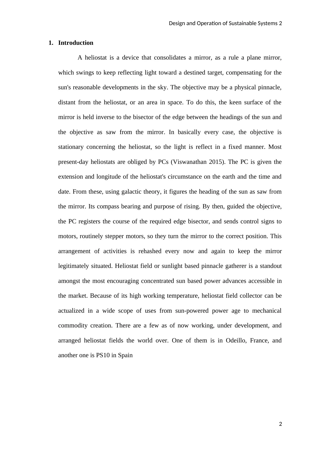
1. Introduction
A heliostat is a device that consolidates a mirror, as a rule a plane mirror,
which swings to keep reflecting light toward a destined target, compensating for the
sun's reasonable developments in the sky. The objective may be a physical pinnacle,
distant from the heliostat, or an area in space. To do this, the keen surface of the
mirror is held inverse to the bisector of the edge between the headings of the sun and
the objective as saw from the mirror. In basically every case, the objective is
stationary concerning the heliostat, so the light is reflect in a fixed manner. Most
present-day heliostats are obliged by PCs (Viswanathan 2015). The PC is given the
extension and longitude of the heliostat's circumstance on the earth and the time and
date. From these, using galactic theory, it figures the heading of the sun as saw from
the mirror. Its compass bearing and purpose of rising. By then, guided the objective,
the PC registers the course of the required edge bisector, and sends control signs to
motors, routinely stepper motors, so they turn the mirror to the correct position. This
arrangement of activities is rehashed every now and again to keep the mirror
legitimately situated. Heliostat field or sunlight based pinnacle gatherer is a standout
amongst the most encouraging concentrated sun based power advances accessible in
the market. Because of its high working temperature, heliostat field collector can be
actualized in a wide scope of uses from sun-powered power age to mechanical
commodity creation. There are a few as of now working, under development, and
arranged heliostat fields the world over. One of them is in Odeillo, France, and
another one is PS10 in Spain
2
Design and Operation of Sustainable Systems 3
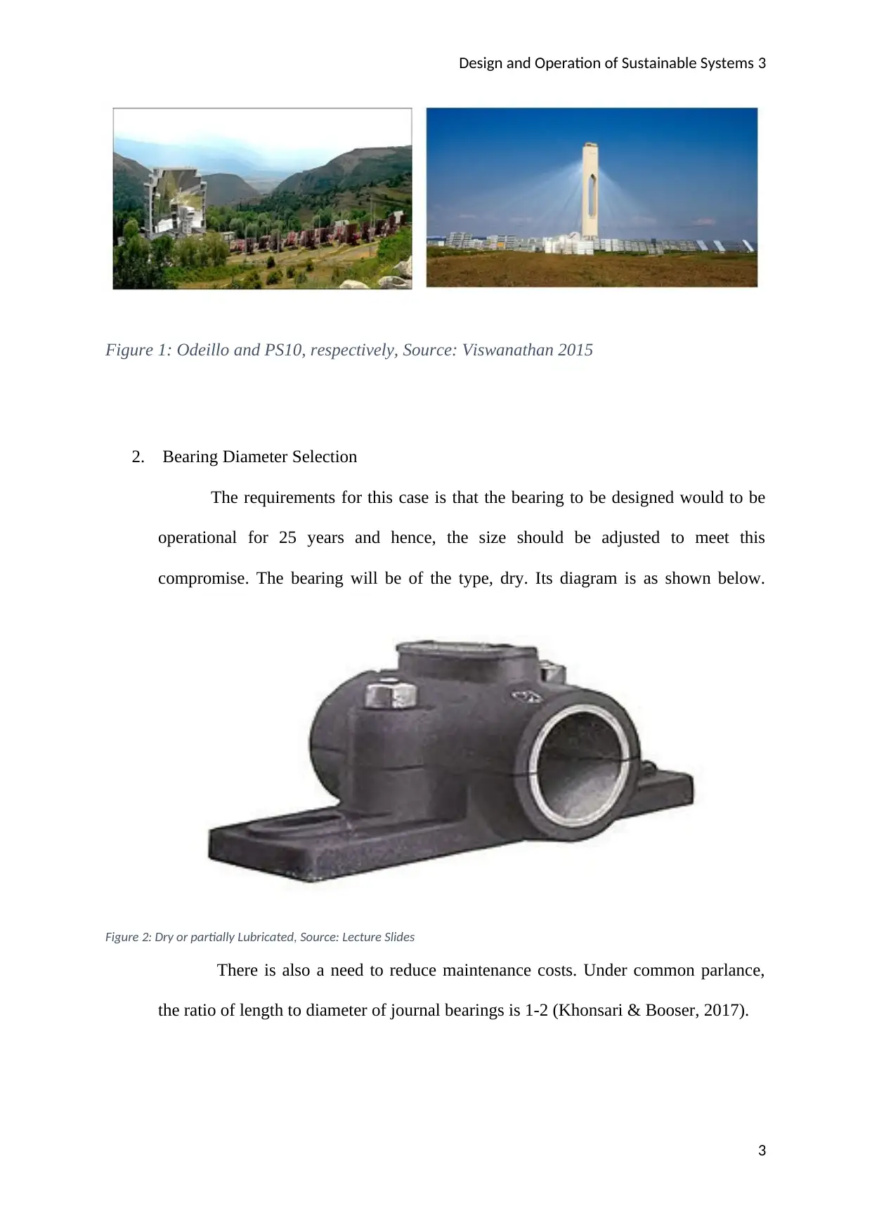
Figure 1: Odeillo and PS10, respectively, Source: Viswanathan 2015
2. Bearing Diameter Selection
The requirements for this case is that the bearing to be designed would to be
operational for 25 years and hence, the size should be adjusted to meet this
compromise. The bearing will be of the type, dry. Its diagram is as shown below.
Figure 2: Dry or partially Lubricated, Source: Lecture Slides
There is also a need to reduce maintenance costs. Under common parlance,
the ratio of length to diameter of journal bearings is 1-2 (Khonsari & Booser, 2017).
3
⊘ This is a preview!⊘
Do you want full access?
Subscribe today to unlock all pages.
Trusted by 1+ million students worldwide
Design and Operation of Sustainable Systems 4
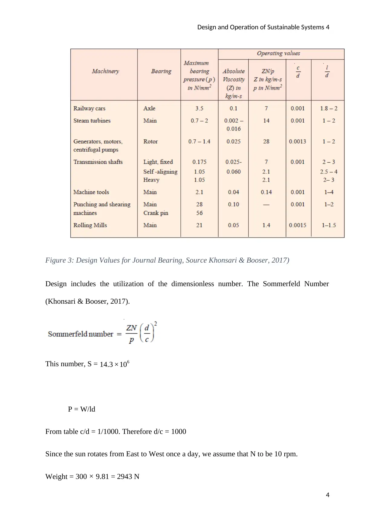
Figure 3: Design Values for Journal Bearing, Source Khonsari & Booser, 2017)
Design includes the utilization of the dimensionless number. The Sommerfeld Number
(Khonsari & Booser, 2017).
This number, S = 14.3 ×10⁶
P = W/ld
From table c/d = 1/1000. Therefore d/c = 1000
Since the sun rotates from East to West once a day, we assume that N to be 10 rpm.
Weight = 300 × 9.81 = 2943 N
4
Paraphrase This Document
Need a fresh take? Get an instant paraphrase of this document with our AI Paraphraser
Design and Operation of Sustainable Systems 5
Between the ranges 1-2 for l/d we pick the value 1.5 which is the mean.
Therefore, l =1.5d,
Hence, P = 1962/d2
Making d2 the subject of the formula, d2 = ( 1962× 14.3 ×106)/ (10002
× 0.25¿
Therefore, d = 335mm
L = 1.5d = 1.5 × 335 = 502.5mm
3. Pressure, forces, and selecting the diameter of bearing
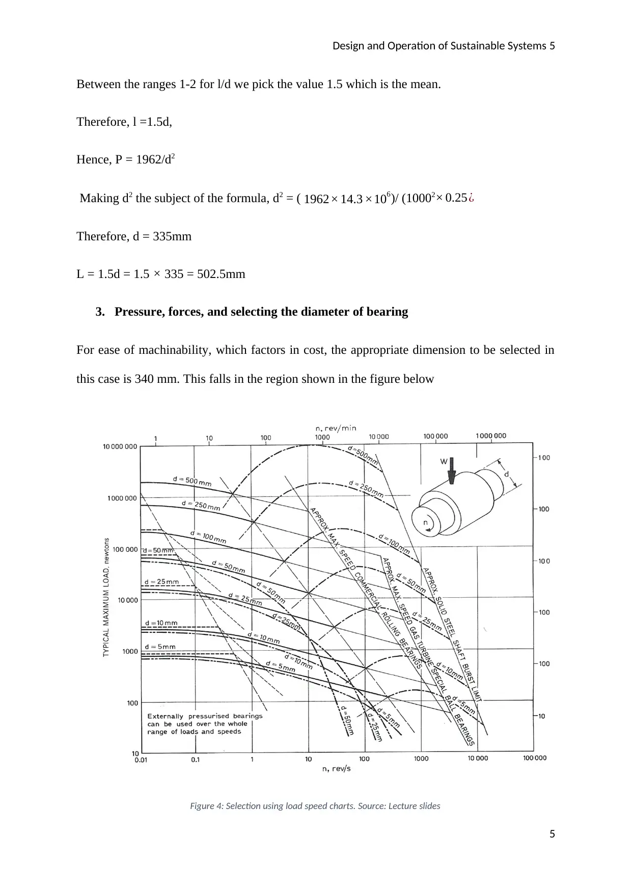
For ease of machinability, which factors in cost, the appropriate dimension to be selected in
this case is 340 mm. This falls in the region shown in the figure below
Figure 4: Selection using load speed charts. Source: Lecture slides
5
Between the ranges 1-2 for l/d we pick the value 1.5 which is the mean.
Therefore, l =1.5d,
Hence, P = 1962/d2
Making d2 the subject of the formula, d2 = ( 1962× 14.3 ×106)/ (10002
× 0.25¿
Therefore, d = 335mm
L = 1.5d = 1.5 × 335 = 502.5mm
3. Pressure, forces, and selecting the diameter of bearing
For ease of machinability, which factors in cost, the appropriate dimension to be selected in
this case is 340 mm. This falls in the region shown in the figure below
Figure 4: Selection using load speed charts. Source: Lecture slides
5
Design and Operation of Sustainable Systems 6
The weight acting perpendicularly on the bearing, w = mg = 2943 N
Using trigonometric equations, we can resolve this force to vertical and horizontal
components. Assuming the angle of inclination is 50 degrees to the tower (Ertas, Marquez,
Hallman, & Smith 2016)
The vertical force = 2943 sin 50 = 2255 N
The horizontal force = 2943 cos 50 = 1893 N
From the above, it is evident that the normal force that = 2943 N
Pressure = W/A = 2943/ (502.5× 335) = 0.0174827 N/mm2
P = 17483 N/m2
4. PV and Max. Specific Wear rate & Material
v = k ∙ W ∙ L
Where
v = the volume of material lost due to friction
W = the weight acting normally
L = the sliding distance.
k = the specific wear rate – whereby values 10-14 or greater indicates the high intensity
of ware whereas values 10-16 or less implies that the wear is moderate.
6
⊘ This is a preview!⊘
Do you want full access?
Subscribe today to unlock all pages.
Trusted by 1+ million students worldwide
Design and Operation of Sustainable Systems 7
wear rate (m3s-1)
time
bedding-in
low wear
mild wear
severe wear
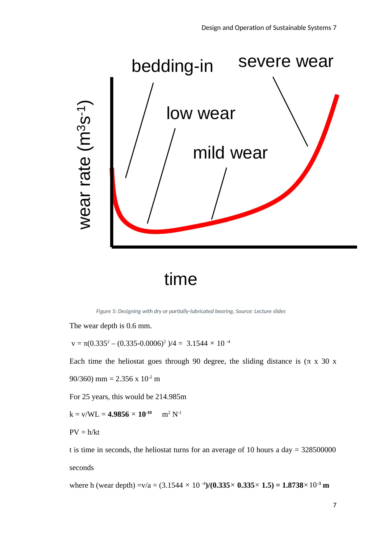
Figure 5: Designing with dry or partially-lubricated bearing, Source: Lecture slides
The wear depth is 0.6 mm.
v = π(0.3352 – (0.335-0.0006)2 )/4 = 3.1544 × 10 -4
Each time the heliostat goes through 90 degree, the sliding distance is (π x 30 x
90/360) mm = 2.356 x 10⁻² m
For 25 years, this would be 214.985m
k = v/WL = 4.9856 × 10⁻¹⁰ m2 N-1
PV = h/kt
t is time in seconds, the heliostat turns for an average of 10 hours a day = 328500000
seconds
where h (wear depth) =v/a = (3.1544 × 10 -4)/(0.335× 0.335× 1.5) = 1.8738×10⁻³ m
7
wear rate (m3s-1)
time
bedding-in
low wear
mild wear
severe wear
Figure 5: Designing with dry or partially-lubricated bearing, Source: Lecture slides
The wear depth is 0.6 mm.
v = π(0.3352 – (0.335-0.0006)2 )/4 = 3.1544 × 10 -4
Each time the heliostat goes through 90 degree, the sliding distance is (π x 30 x
90/360) mm = 2.356 x 10⁻² m
For 25 years, this would be 214.985m
k = v/WL = 4.9856 × 10⁻¹⁰ m2 N-1
PV = h/kt
t is time in seconds, the heliostat turns for an average of 10 hours a day = 328500000
seconds
where h (wear depth) =v/a = (3.1544 × 10 -4)/(0.335× 0.335× 1.5) = 1.8738×10⁻³ m
7
Paraphrase This Document
Need a fresh take? Get an instant paraphrase of this document with our AI Paraphraser
Design and Operation of Sustainable Systems 8
PV = (1.8738×10⁻³)/ (4.9856 × 10-10 ×328500000) = 0.01144 N/ms
Material selection
There is an important selection criterion. The first criteria are load, and in this case,
we consider our journal is bearing to have a steady load. Considering the speed too,
the speed is steady and low. The environment to which the material is subjected to has
no vibrations but is prone to dust. The life of the material should be at least, 25 years.
In the selection of the material, the consideration includes the cost of the material, its
availability, bonding, corrosion resistance, embeddability, elasticity, high thermal
conductivity, low thermal expansion, high fatigue strength, high compressive
strength, low coefficient of friction and relative hardness of the bearing material
(Jahan, Edwards, &Bahraminasab 2016). The bearing material ought to typically be
gentler than that of the journal to forestall shaft wear however sufficiently hard to
oppose cement, and rough wear of its surface Bearings are simple to supplant than
shafts (that require destroying of the entire motor). In the event that one bearing is
exhausted just that bearing needs substitution rather than the entire shaft. The selected
metal is Babbitt. SAE 11 Babbitt is utilized for the course which are exposed to
overwhelming weights. SAE 10 Babbitt is likewise appropriate for overwhelming
weights; it is liquid and can be connected for meager linings of bronze-supported or
steel-upheld bearing shells like those utilized in the car and flying machine motors.
Lead-base Babbitt might be utilized for bigger course when most extreme weights are
beneath 500 psi. in any case, a toxic composite with the trade name Magnolia Metal,
the investigation of which is about equivalent to that of SAE 14 Babbitt, appears to
give great administration even in substantial direction in the event that they are
exposed to beating (Babu, Krishna, & Suman 2015). Brass is utilized where the
weight is unreasonably high for Babbit; however where the administration isn't
8
Design and Operation of Sustainable Systems 9
extreme enough to require a progressively costly bearing metal. Bronzes are utilized
where the weights are high to the point that slim film grease may happen. Nylon is
suitable also in this case because it can with stand the high frictional force and high
friction coefficient.
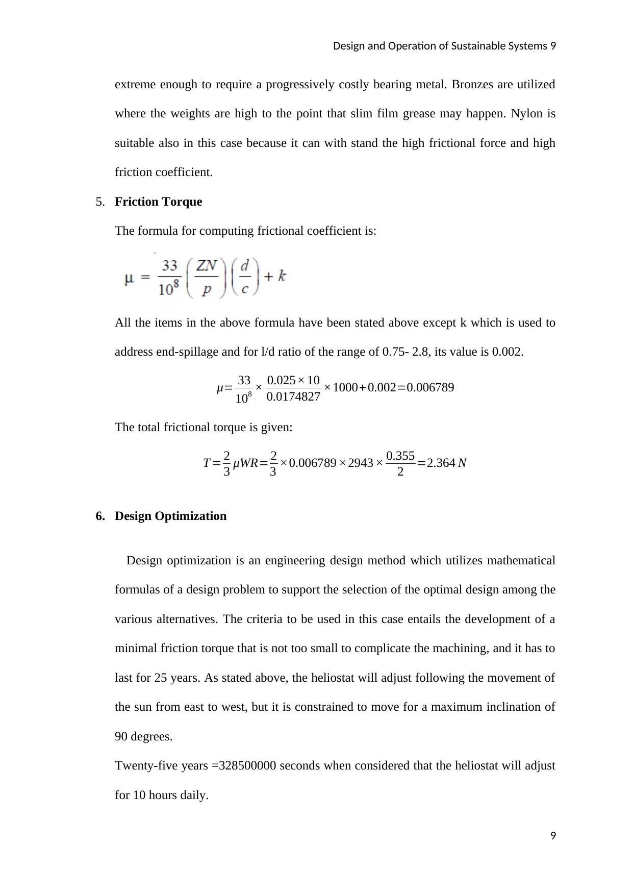
5. Friction Torque
The formula for computing frictional coefficient is:
All the items in the above formula have been stated above except k which is used to
address end-spillage and for l/d ratio of the range of 0.75- 2.8, its value is 0.002.
μ= 33
108 × 0.025× 10
0.0174827 ×1000+ 0.002=0.006789
The total frictional torque is given:
T = 2
3 μWR= 2
3 ×0.006789 ×2943 × 0.355
2 =2.364 N
6. Design Optimization
Design optimization is an engineering design method which utilizes mathematical
formulas of a design problem to support the selection of the optimal design among the
various alternatives. The criteria to be used in this case entails the development of a
minimal friction torque that is not too small to complicate the machining, and it has to
last for 25 years. As stated above, the heliostat will adjust following the movement of
the sun from east to west, but it is constrained to move for a maximum inclination of
90 degrees.
Twenty-five years =328500000 seconds when considered that the heliostat will adjust
for 10 hours daily.
9
extreme enough to require a progressively costly bearing metal. Bronzes are utilized
where the weights are high to the point that slim film grease may happen. Nylon is
suitable also in this case because it can with stand the high frictional force and high
friction coefficient.
5. Friction Torque
The formula for computing frictional coefficient is:
All the items in the above formula have been stated above except k which is used to
address end-spillage and for l/d ratio of the range of 0.75- 2.8, its value is 0.002.
μ= 33
108 × 0.025× 10
0.0174827 ×1000+ 0.002=0.006789
The total frictional torque is given:
T = 2
3 μWR= 2
3 ×0.006789 ×2943 × 0.355
2 =2.364 N
6. Design Optimization
Design optimization is an engineering design method which utilizes mathematical
formulas of a design problem to support the selection of the optimal design among the
various alternatives. The criteria to be used in this case entails the development of a
minimal friction torque that is not too small to complicate the machining, and it has to
last for 25 years. As stated above, the heliostat will adjust following the movement of
the sun from east to west, but it is constrained to move for a maximum inclination of
90 degrees.
Twenty-five years =328500000 seconds when considered that the heliostat will adjust
for 10 hours daily.
9
⊘ This is a preview!⊘
Do you want full access?
Subscribe today to unlock all pages.
Trusted by 1+ million students worldwide
Design and Operation of Sustainable Systems 10
Therefore,
ω = 90 x (2π)/(360 × 10 × 3600) rad/s = 4.36 × 10⁻⁵ rad/s
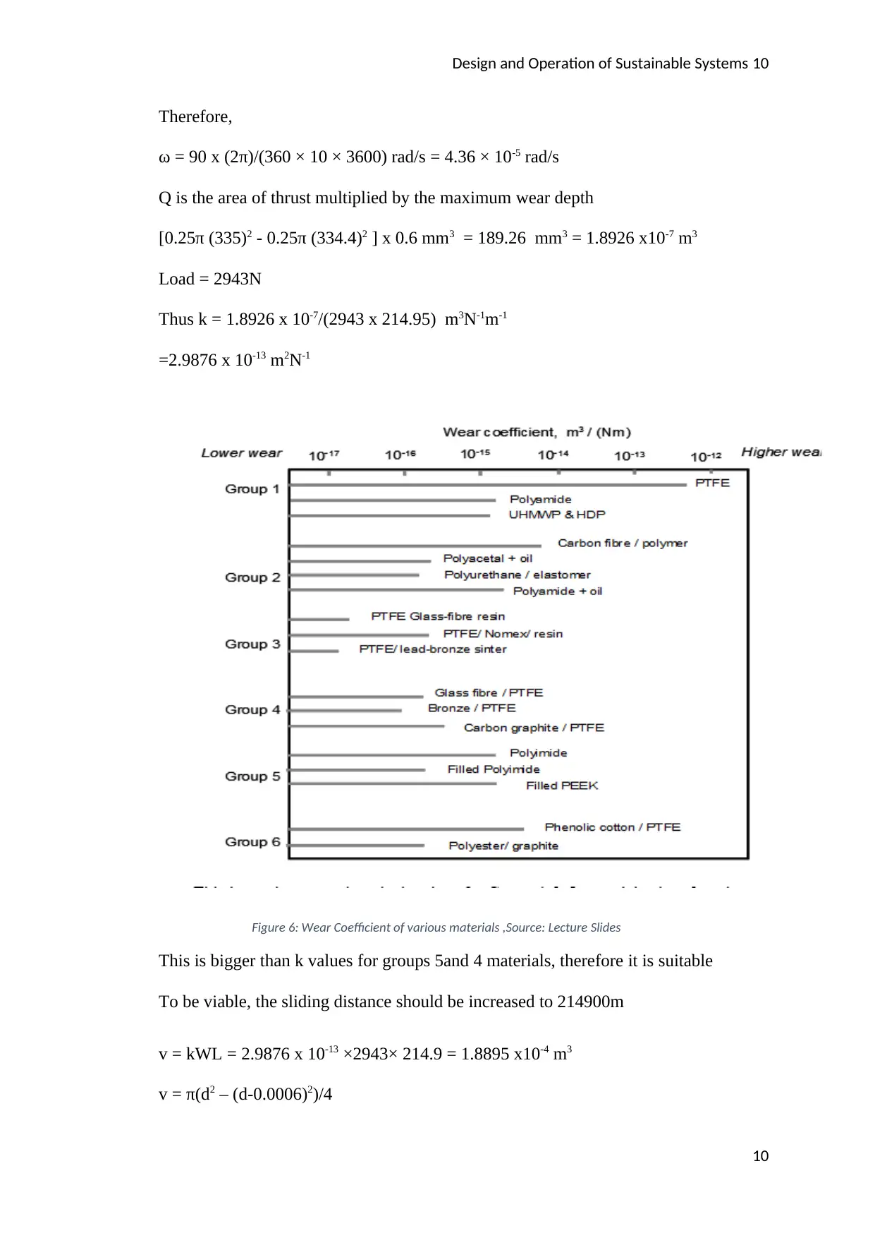
Q is the area of thrust multiplied by the maximum wear depth
[0.25π (335)2 - 0.25π (334.4)2 ] x 0.6 mm3 = 189.26 mm3 = 1.8926 x10⁻⁷ m3
Load = 2943N
Thus k = 1.8926 x 10⁻⁷/(2943 x 214.95) m3N-1m-1
=2.9876 x 10⁻¹³ m2N-1
Figure 6: Wear Coefficient of various materials ,Source: Lecture Slides
This is bigger than k values for groups 5and 4 materials, therefore it is suitable
To be viable, the sliding distance should be increased to 214900m
v = kWL = 2.9876 x 10-13 ×2943× 214.9 = 1.8895 x10⁻⁴ m3
v = π(d2 – (d-0.0006)2)/4
10
Therefore,
ω = 90 x (2π)/(360 × 10 × 3600) rad/s = 4.36 × 10⁻⁵ rad/s
Q is the area of thrust multiplied by the maximum wear depth
[0.25π (335)2 - 0.25π (334.4)2 ] x 0.6 mm3 = 189.26 mm3 = 1.8926 x10⁻⁷ m3
Load = 2943N
Thus k = 1.8926 x 10⁻⁷/(2943 x 214.95) m3N-1m-1
=2.9876 x 10⁻¹³ m2N-1
Figure 6: Wear Coefficient of various materials ,Source: Lecture Slides
This is bigger than k values for groups 5and 4 materials, therefore it is suitable
To be viable, the sliding distance should be increased to 214900m
v = kWL = 2.9876 x 10-13 ×2943× 214.9 = 1.8895 x10⁻⁴ m3
v = π(d2 – (d-0.0006)2)/4
10
Paraphrase This Document
Need a fresh take? Get an instant paraphrase of this document with our AI Paraphraser
Design and Operation of Sustainable Systems 11
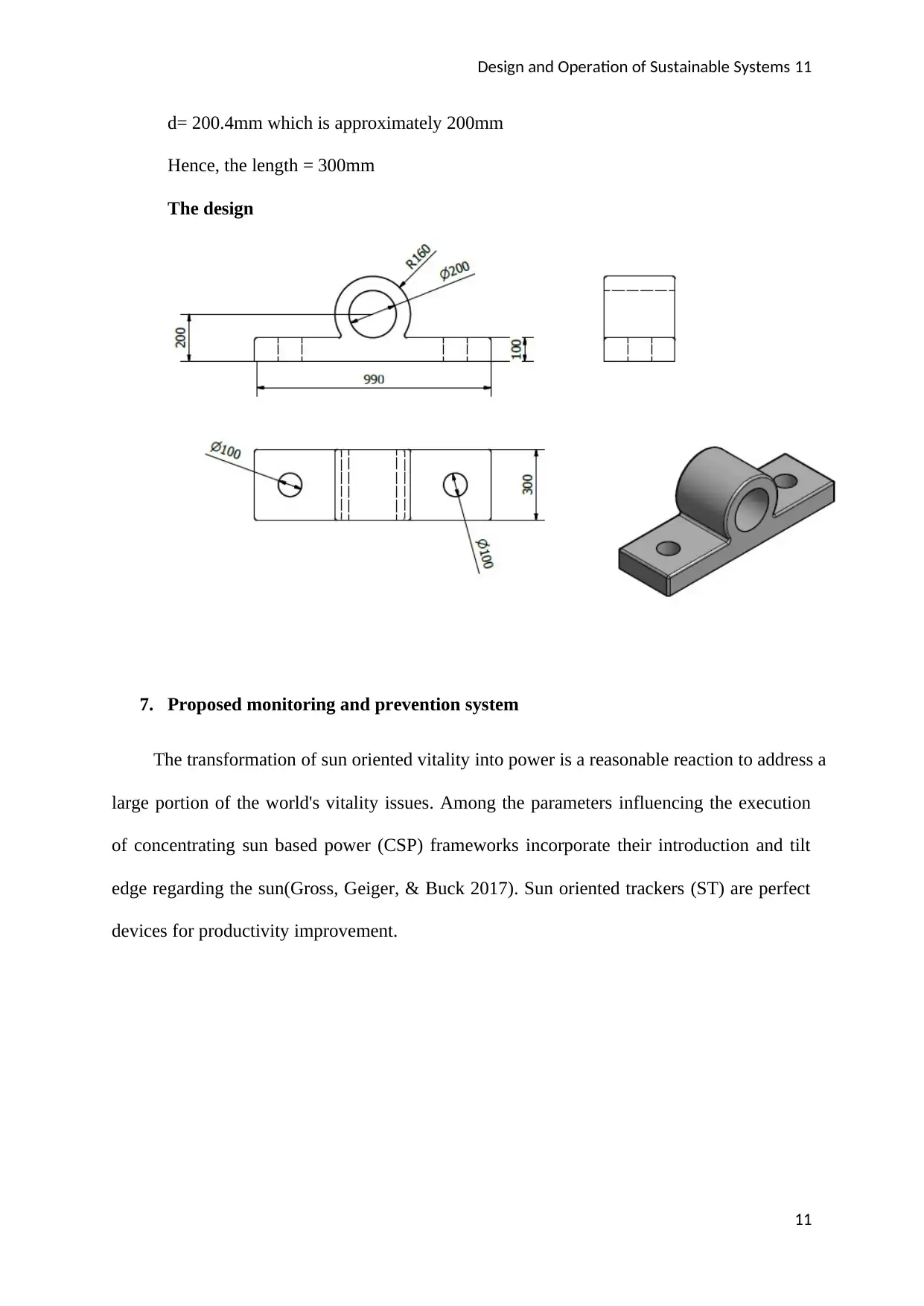
d= 200.4mm which is approximately 200mm
Hence, the length = 300mm
The design
7. Proposed monitoring and prevention system
The transformation of sun oriented vitality into power is a reasonable reaction to address a
large portion of the world's vitality issues. Among the parameters influencing the execution
of concentrating sun based power (CSP) frameworks incorporate their introduction and tilt
edge regarding the sun(Gross, Geiger, & Buck 2017). Sun oriented trackers (ST) are perfect
devices for productivity improvement.
11
Design and Operation of Sustainable Systems 12
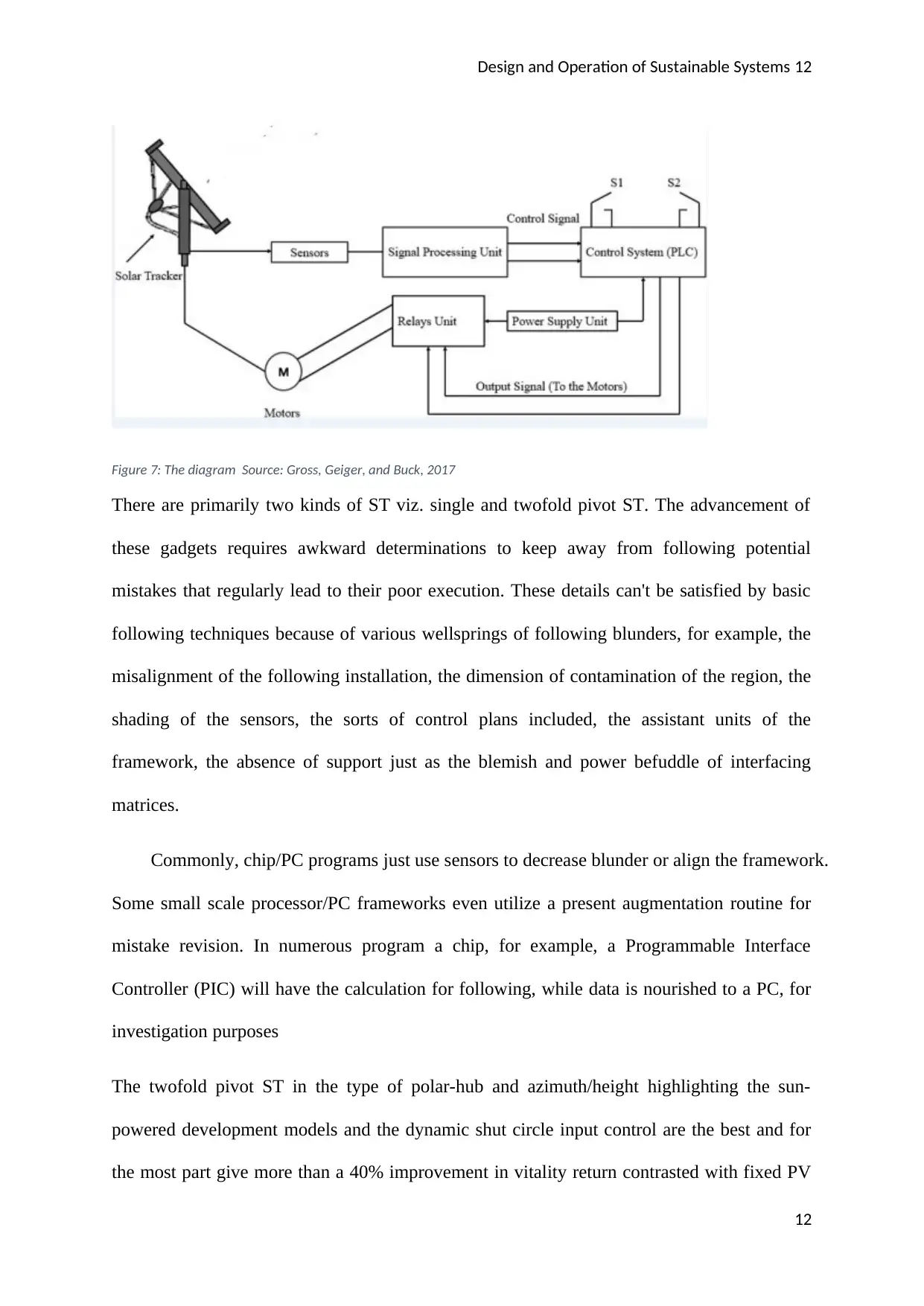
Figure 7: The diagram Source: Gross, Geiger, and Buck, 2017
There are primarily two kinds of ST viz. single and twofold pivot ST. The advancement of
these gadgets requires awkward determinations to keep away from following potential
mistakes that regularly lead to their poor execution. These details can't be satisfied by basic
following techniques because of various wellsprings of following blunders, for example, the
misalignment of the following installation, the dimension of contamination of the region, the
shading of the sensors, the sorts of control plans included, the assistant units of the
framework, the absence of support just as the blemish and power befuddle of interfacing
matrices.
Commonly, chip/PC programs just use sensors to decrease blunder or align the framework.
Some small scale processor/PC frameworks even utilize a present augmentation routine for
mistake revision. In numerous program a chip, for example, a Programmable Interface
Controller (PIC) will have the calculation for following, while data is nourished to a PC, for
investigation purposes
The twofold pivot ST in the type of polar-hub and azimuth/height highlighting the sun-
powered development models and the dynamic shut circle input control are the best and for
the most part give more than a 40% improvement in vitality return contrasted with fixed PV
12
⊘ This is a preview!⊘
Do you want full access?
Subscribe today to unlock all pages.
Trusted by 1+ million students worldwide
1 out of 14


Your All-in-One AI-Powered Toolkit for Academic Success.
+13062052269
info@desklib.com
Available 24*7 on WhatsApp / Email
![[object Object]](/_next/static/media/star-bottom.7253800d.svg)
Unlock your academic potential
Copyright © 2020–2026 A2Z Services. All Rights Reserved. Developed and managed by ZUCOL.