Impact of Switching Frequency on Power Quality: A Detailed Analysis
VerifiedAdded on 2023/03/21
|20
|5484
|72
Report
AI Summary
This report delves into the critical relationship between switching frequency technology and power quality, focusing on its influence on various electrical components and systems. It begins with an introduction to switching frequency and its implications for power quality, including the reduction of device sizes and improved power factor. The report then explores the objectives and aims of analyzing this impact, followed by a comprehensive literature review. The literature review covers topics such as the improvement of power factor, the role of variable frequency drives (VFDs) in motor control and energy efficiency, and the use of different control methods for power factor correction. The theoretical background section explains the function of switched mode power supplies (SMPS) and their components. The report provides a detailed analysis of the impact of switching frequency on power quality, offering insights into practical applications and theoretical underpinnings. The report is a valuable resource for understanding the significance of switching frequency in electrical engineering.

SWITCHING
FREQUENCY
TECHNOLOGY AND
POWER QUALITY
FREQUENCY
TECHNOLOGY AND
POWER QUALITY
Paraphrase This Document
Need a fresh take? Get an instant paraphrase of this document with our AI Paraphraser

INTRODUCTION
• Basically, the technology of the switching frequency in a converter or an inverter is the rate at
which the used switching device is turned off and on during the DC voltage pulse width
modulation process of switching power supply. This technology of the switching frequency has
significant impacts on power quality. For instance, higher switching frequency helps in reducing
the sizes which are linked to the devices like transformers, resistors, capacitors, inductors among
others. It also helps in reducing the required space on the board as well as the cables employed
in the installation of these different components. The switching frequency has a great effect on
the quality of power; some of these include the following;
• Higher switching frequency increases the power factor which is very significant in improving the
power quality utilized.
• The technology of frequency switching is also employed in motor control where Variable
frequency drives are employed. This variable frequency drives which use the principles of
frequency switching help in the reduction of energy consumed as the AC motor operates.
• At higher switching frequency the sizes of electrical devices reduce in size hence less costly.
Such devices include capacitor, resistors, and inductors.
• The square waves or the sine waves which are basically employed to convert the rectified or Dc
voltage to a higher frequency (Deng, 2015). The PFM which is known as the pulse Frequency
Modulation increases the variable switching frequency thus governing the number of times the
device is switching ON and OFF for every second. For this switching technology, the PFM should
have constant OFF time and constant ON time. For most cases the square wave is employed in
frequency switching since it is very easy to filter and to control the square waves as compared to
the sine waves (Xu, 2016). The diagram below illustrates the prototype of a typical switched mode
power supply which can be employed in switching frequency.
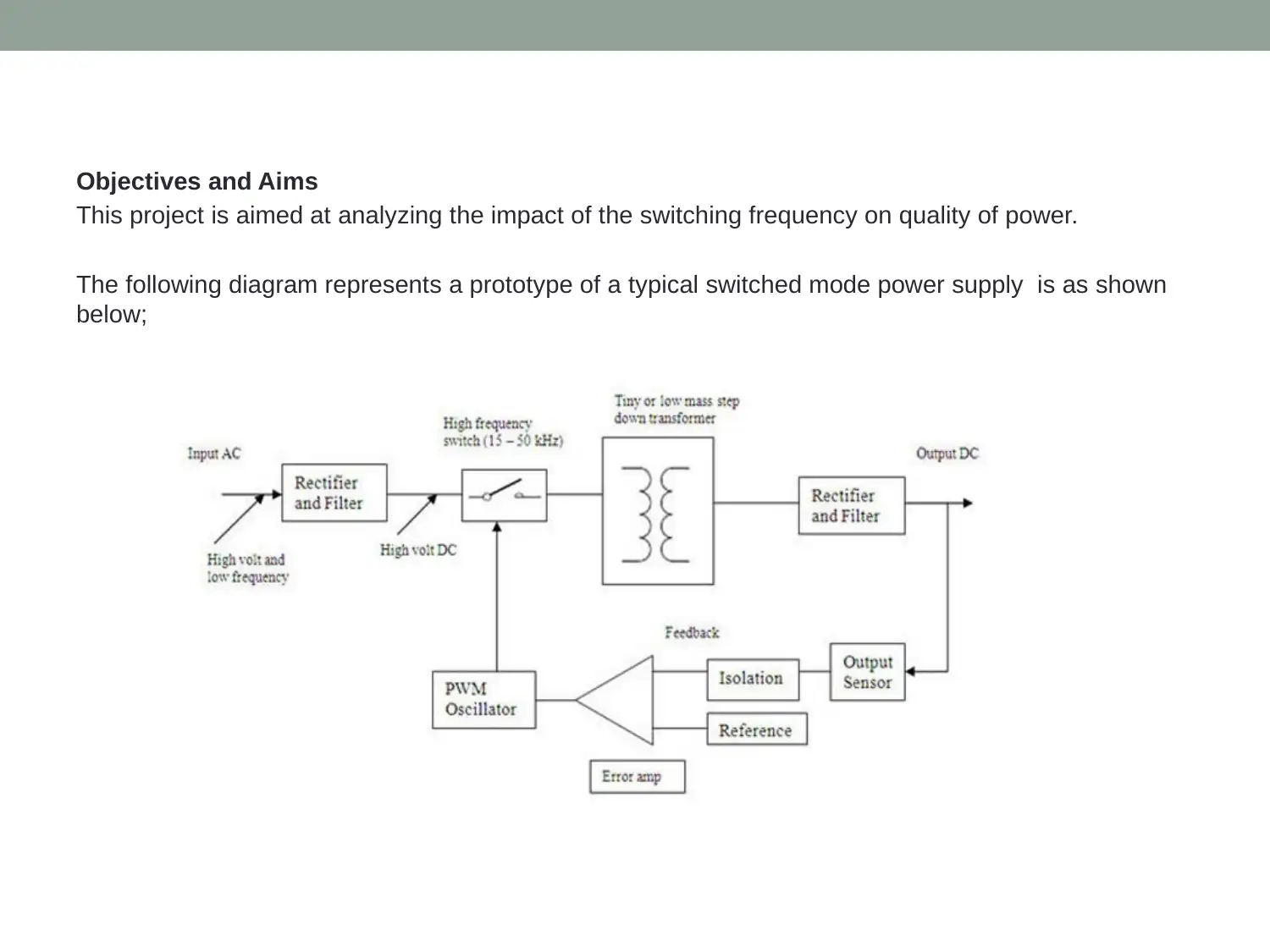
Objectives and Aims
This project is aimed at analyzing the impact of the switching frequency on quality of power.
The following diagram represents a prototype of a typical switched mode power supply is as shown
below;
This project is aimed at analyzing the impact of the switching frequency on quality of power.
The following diagram represents a prototype of a typical switched mode power supply is as shown
below;
⊘ This is a preview!⊘
Do you want full access?
Subscribe today to unlock all pages.
Trusted by 1+ million students worldwide

LITERATURE REVIEW
Increase the power factor
• Currently, the switching frequency is very common for electrical power usage in most electrical components. A
conventional AC connected power basically has a full wave diode rectifier having a big capacitive output filter (Chen,
2018). This then leads to important AC line current distorted, therefore, degrading the input power quality. This is true
since the poor power quality can result in ineffective usage on the electrical grid and also can result in damage to the
electrical devices (Al-Haddad, 2015). Thus the higher switching frequency is preferred as the major components
characterizing the quality of power are power factor of the input current. Through definition active power ratio to
apparent power is given as below;
• PF= . . . . . . . . . . . . . . . . . . . . . . . . . . . . . . . . . . . . . . . . . . . . . . . . . . . . . . . . . . . 1
• Where PF is the power factor, Peal is the real or active power, Vin rams is the input rms value and I in rms is the input
rms current value.
• And it is also known that the power factor is a function of phase which is between the input current and voltage
fundament a harmonic can also be given by the following equation 2;
• PF= . . . . . . . . . . . . . . . . . . . . . . . . . . . . . . . . . . . . . . . . . . . . . . . . . . . . . . . . . . . . . . . . . 2
•
• Where THD is the total harmonic distortion,
• From equation 2 above when the THD input current is increased, the value of power factor will be reduced this will
result in degradation of power quality of the input power. Power Factor correction converter can work either in
discontinuous mode, continuous mode or conduction mode. These converters are made work in the discontinuous
mode for applications which require very low power consumptions (Li, 2015). For an adjusted control method to lower
the THD, the current at the input and improvement of the power factor of the discontinuous conduction mode of the
power factor correction.
• For boosting power factor using the switching frequency there are some three main control methods, these include the
average current control methods, hysteresis control as well as the peak current control (Wang, 2017). But of the three
the average current control method is mostly preferred over the other two since it has relatively higher immunity to
noise, therefore, it is not easily affected by the noise. The schematic diagram for the average current control is
illustrated using the following diagram;
Paraphrase This Document
Need a fresh take? Get an instant paraphrase of this document with our AI Paraphraser

l
A diagram showing the average current method for boost
power factor correction converter .
A diagram showing the average current method for boost
power factor correction converter .

Variable frequency drives
•Its purpose is to regulate the energy flow from the mains to the motor shaft. Supply of energy process is through the motor shaft. The description of the nature of
the shaft that is the torque and speed is given in two physical quantities. To regulate the energy flow from the mains to the process, torque and speed control is
important (Lorenz, 2016). One of these quantities is controlled in industrial applications either in torque control or the speed control modes. When operated in
torque control mode, the VSD speed is determined by the load at the motor shaft and the torque is controlled by the load at the motor shaft when operated in
speed control mode (Williams, 2018).
•“The purpose of VFDs is to control the AC induction motors that may be driving loads such as fans, pumps, conveyors so as to function in a wide range of speeds
as opposed to DOL method that is limited to a speed that is fixed (Lorenz, 2016). The referrals of these VFDs are usually included variable frequency drives,
adjustable speed drives, frequency inverters or converters. VFDS installations can increase the efficiency and saving of energy up to 50% when compared to a
DOL installation (Leon, 2017). The running of VFDS is at a high power factor in electronic form. Any induction class of motors always contains the power factor at
the half and three-quarter loads (0.75 to 0.85).
•Therefore the span of the motor is decreased since the increase in current unnecessarily overheats the winding insulation. Running the load at a frequency below
the fundamentals, the VFDS overcome this shortcoming ( Agamloh, 2016).The VDFs are procured through speed control. They are always conducted for the
procedure, operations and the benefits of the economy. One benefit comes from the maintenance reduction when the VFDS are being used, particularly when
dealing with the DC motors carbon brushes or mechanical speed control gearboxes is not applied (John, 2015). The most common economic benefit of VFDS
involves the fans and the pumps. The consumption of power by the pumps and the fans is directly proportional to the cubes of the velocity. If the fun can be used
by the operator at 80% of full speed, it theoretically uses 51% of full load power.
•The VFDs also has the characteristics of the motor which is starting optimization (Kissin, 2019). They bring motors up to a quick full speed and by drawing only
100% to 150% of full loads amps (FLAs). The importance of this ability to start at normal FLA if the power supply withstanding the normally six times FLA is a
problem the starting across draw line or even the soft start device current of 350% (Felix, 2016). VFDS manage this by inducting motors through the magnetic
flux. Voltage is directly proportional to the magnetic flux while the magnetic flux is inversely proportional to the frequency. The flux is kept constant so that the
inrush current does not exceed the FLA rating of the motor together with maintenance the full torque. This improvement is essential on soft start, that contains the
important problem of voltage drop and starting under the full load is not possible.
•The output of constant torque is the other potential useful aspect of VDFs. The two locations include constant torque and constant horsepower. The region of
constant torque is somehow explaining itself. The VFD is the flux regulating so as the constant current is maintained. The voltage of the VFD cannot increase as
a result of the physical constraint of the system due to the static voltage and the increased frequency once the VDFS surpasses the system frequency rated;
hence the flux is forced to decrease this forces the current and the torque also to decrease. It is referred to as field weakening (Zargari, 2017). It is important in
case the torque needs to be powered partially above the rated speed although it is not a good idea. An additional capability of this VDFS is that it can take any
form of input power either single-phase AC, 3 phases AC or DC. They fed DC source that powers an AC load without an internal rectifier.
•The energy cost savings and speed control are one of the main advantages of using VDF. The application of belts, sheaves or gearboxes to reduce speed leads
the motor to continue running at full speed; however, VFD reduces the used amount of energy hence saving the cost of energy by reducing slowly the motor
speed, it also assists the consumers to save the energy by the in-rush and mechanical issues reduction associated with starting the motors across the line”
(Ingram, 2017).
•Saving your money by VFD can be achieved by increasing the efficiency of the AC motor and decreasing the electricity use which is the first and common means.
The saved amount of energy depends on the average load of the motors and the number of hours turned on per day. The ability to save energy varies, most AC
motors do not require the full capacity for most hours of their use. Furthermore, the startup cost of these motors is only a portion of the operating cost over its life
span (Jung, 2017). This shows that the system caters for itself in months and years matters.
•A motor of 25 horsepower fan and its operation is 23 hours a day is likely to run at a full capacity of the full 23 hours. If the units are operated at full capacity for
two hours, 75% and 67% for eight hours and 50% capacity for 5 hours, the energy reduction by the motor will be 32%. Extending the span of your motor is
another means a VFDS is economical. It reduces the AC motor’s fluid flow, which in turns reduces the pressure and friction on the valves and other machinery into
the motors (Smith, 2018). Reduction of the wear and tear can be achieved by reducing the running capacity.
⊘ This is a preview!⊘
Do you want full access?
Subscribe today to unlock all pages.
Trusted by 1+ million students worldwide

circuit diagram of the VFD
Paraphrase This Document
Need a fresh take? Get an instant paraphrase of this document with our AI Paraphraser

THEORETICAL BACKGROUND
• “A switched mode power supply contains the following components that are the switching mode power supply, the switch mode power supply,
switched power supply, SMPS or the switcher (Radovinsky, 2018). It contains the supply of power that is electronic which uses a switching
regulator to convert electrical power efficiently. An SMPS transmit power from DC to AC which is the main power to the DC loads which include
personal computers while converting the voltage and current characteristics. The pass transistor of a switching mode supply continue to switch
between low dissipation, full on and full off states, unlike the linear power supply which spend little time in the high dissipation transitions that
reduce the energy wastage. Generally, it does not require more power.
• Variation of the ratio of on to off time is one so as to achieve voltage regulations (Quinn, 2018). However, the regulation of the linear power
supply is achieved by regularly removing power in the pass transistor. The essential advantage of this switched mode power supply is its
ability and efficiency of converting the higher power. Another disadvantage is that it is smaller in size and also light in weight as compared to
linear supply due to the smaller transformer size and weight (Jung, 2016).
• When these properties of smaller size and lighter weight are require, replacement of linear regulations is achieved by the use of switching
regulators. However, they are not comprehensible. When switching the currents, the electrical noise problem can be generated if not properly
suppressed and simple design may have a poor power factor. Conversion of AC to DC is the first step in case the SMPS has an AC power
supply in a process called rectification. Although the one having DC power, this process is not required (Gárate, 2016). The rectifier circuit can
be configured in case where the computers ATX power supply is needed as a voltage double by adding a switch operated either manually or
automatically.
• This characteristic allows the performance from a power source that are usually 115 V or 230V. The unmeasured generated DC voltage by the
rectifier is then transferred to a large filter capacity (Garces, 2016). The drawn current from the main supply by this circuit takes place in short
pulses around the AC voltage peaks. The power factor is minimized by these pulses which has a significantly high frequency. The new SMPS
have been invented which uses a special PFC circuit to make the current follow the shape of a sinusoidal of the AC input voltage so as to
correct this problem of power factor. The supplies of power that is generated by the active PFC always are auto ranging, supporting input
voltages from 100 VAC - 250 VAC without voltage selector switch (Malloy, 2015).
• An SMPS that has been designed for the purpose of AC input is usually operated from DC supply since the DC would pass through the rectifier
which remains unchanged. For instance, if the supply of power is designed for 115 VAC, the needed DC voltage would be 163 VDC if the
voltage selector does not exist. This user type is dangerous to the rectifier stage (Khaligh, 2016). How are the used diodes in the rectifier mat
be Alf for a full load. This may lead to overheating of these structures leading them to fail to mature. In addition, if the lodge selector exists,
according to Delon circuit, for about 115/230 V, the selector switch will have to be positioned in 230v. And the needed energy will be 325 VDC.
• The diodes at this power supply type are handled by the DC current just fine since they are rated to double the nominal input current when
running he 115V mode, due to double voltage operation. Since, when the double is in operation they only consume a fraction of the rectifier
bridge and operate twice as much current through it. Therefore can be said that the switching frequency technologies are actually good
technologies which have been employed for several years to help to improve the power quality which is employed in both domestic as well as
industrial applications” (Milanovič, 2015).
• As given in the above sections, it has been seen that switching frequency basically improves the power factor of the supplied electrical power.
With the higher power factor, the quality of the power is really high since then there is more active power as opposed to reactive power which is
always treated as the "fake" power which makes the cost of power to be expensive for no apparent reason (Biricik, 2016). With the higher
switching frequency, the electrical gadgets are reduced in size, these gadgets include the transformers, resistors, capacitors electrical cables
which will also help in reducing the cost of installation of electrical power thus improves the power quality (Li, 2018).

BOOST PFC DESCRIPTION USING SIMULINK MODEL
• The creation and explanation of PFC converter are given in the
analysis of the SIMULINK model. “The model figure below is applied
for simulation of boost PFC converter with or without SFM. The model
is partly operated under the schematic figure shown below with some
simplification. Simulation of this results may be achieved through
comparing the experimental results, values of power inductors
inductance, output capacitors capacitance and also 360W boost PFC
converter explained in this model in which the equal parasitic
resistance series of the output capacitor and power inductor are taken
into account. However, linear inductors are assumed.
• So as to put in place the real power MOSFET and its control circuit
involving PWM switch turn-on delay and the turn off switch delay,
which for instance they have the most influence on low-frequency
contest of switching frequency, modulated dc power converters
voltage, that is the turn on and of delay blocks involving two transport
delay blocks.” The logic operator is also added to this model so as the
tdon and tdoff values can be entered independently using the block.
⊘ This is a preview!⊘
Do you want full access?
Subscribe today to unlock all pages.
Trusted by 1+ million students worldwide

circuit diagram of PFC under simulation
Paraphrase This Document
Need a fresh take? Get an instant paraphrase of this document with our AI Paraphraser
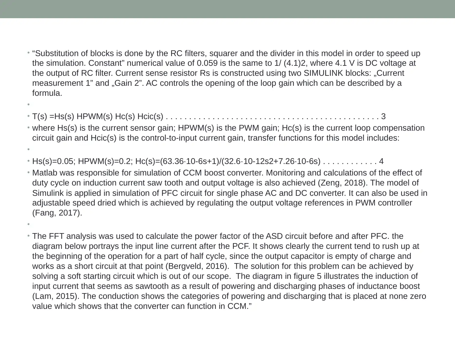
• “Substitution of blocks is done by the RC filters, squarer and the divider in this model in order to speed up
the simulation. Constant” numerical value of 0.059 is the same to 1/ (4.1)2, where 4.1 V is DC voltage at
the output of RC filter. Current sense resistor Rs is constructed using two SIMULINK blocks: „Current
measurement 1” and „Gain 2”. AC controls the opening of the loop gain which can be described by a
formula.
•
• T(s) =Hs(s) HPWM(s) Hc(s) Hcic(s) . . . . . . . . . . . . . . . . . . . . . . . . . . . . . . . . . . . . . . . . . . . . . . 3
• where Hs(s) is the current sensor gain; HPWM(s) is the PWM gain; Hc(s) is the current loop compensation
circuit gain and Hcic(s) is the control-to-input current gain, transfer functions for this model includes:
•
• Hs(s)=0.05; HPWM(s)=0.2; Hc(s)=(63.36∙10-6s+1)/(32.6·10-12s2+7.26∙10-6s) . . . . . . . . . . . . 4
• Matlab was responsible for simulation of CCM boost converter. Monitoring and calculations of the effect of
duty cycle on induction current saw tooth and output voltage is also achieved (Zeng, 2018). The model of
Simulink is applied in simulation of PFC circuit for single phase AC and DC converter. It can also be used in
adjustable speed dried which is achieved by regulating the output voltage references in PWM controller
(Fang, 2017).
•
• The FFT analysis was used to calculate the power factor of the ASD circuit before and after PFC. the
diagram below portrays the input line current after the PCF. It shows clearly the current tend to rush up at
the beginning of the operation for a part of half cycle, since the output capacitor is empty of charge and
works as a short circuit at that point (Bergveld, 2016). The solution for this problem can be achieved by
solving a soft starting circuit which is out of our scope. The diagram in figure 5 illustrates the induction of
input current that seems as sawtooth as a result of powering and discharging phases of inductance boost
(Lam, 2015). The conduction shows the categories of powering and discharging that is placed at none zero
value which shows that the converter can function in CCM.”

Showing PFC of the discharging phase using SIMULINK
⊘ This is a preview!⊘
Do you want full access?
Subscribe today to unlock all pages.
Trusted by 1+ million students worldwide
1 out of 20
Related Documents


Your All-in-One AI-Powered Toolkit for Academic Success.
+13062052269
info@desklib.com
Available 24*7 on WhatsApp / Email
![[object Object]](/_next/static/media/star-bottom.7253800d.svg)
Unlock your academic potential
Copyright © 2020–2026 A2Z Services. All Rights Reserved. Developed and managed by ZUCOL.