EE582 Power System Transients Project: Switching Impulse on EHV Line

Verified

Added on  2022/09/09

|5
|537
|28
Project
AI Summary
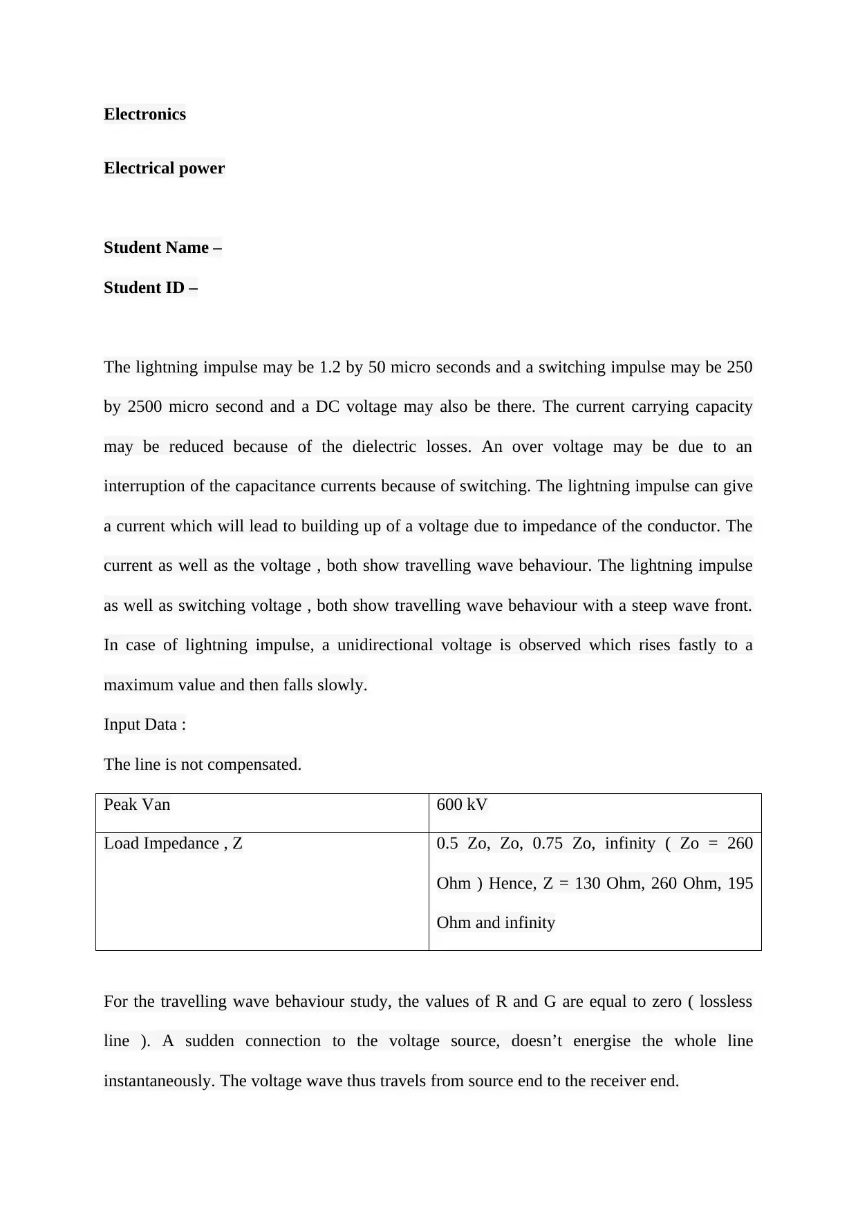
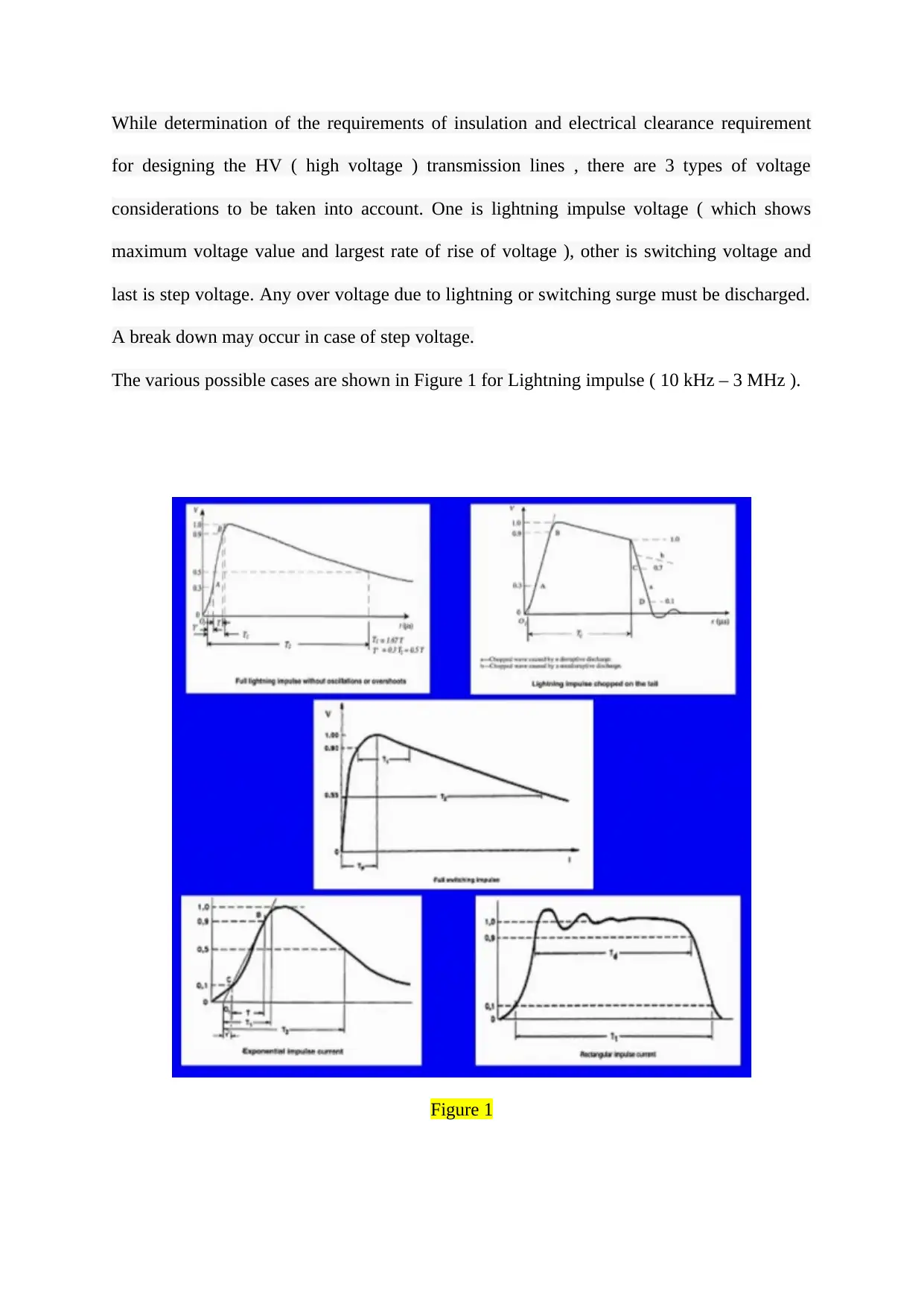
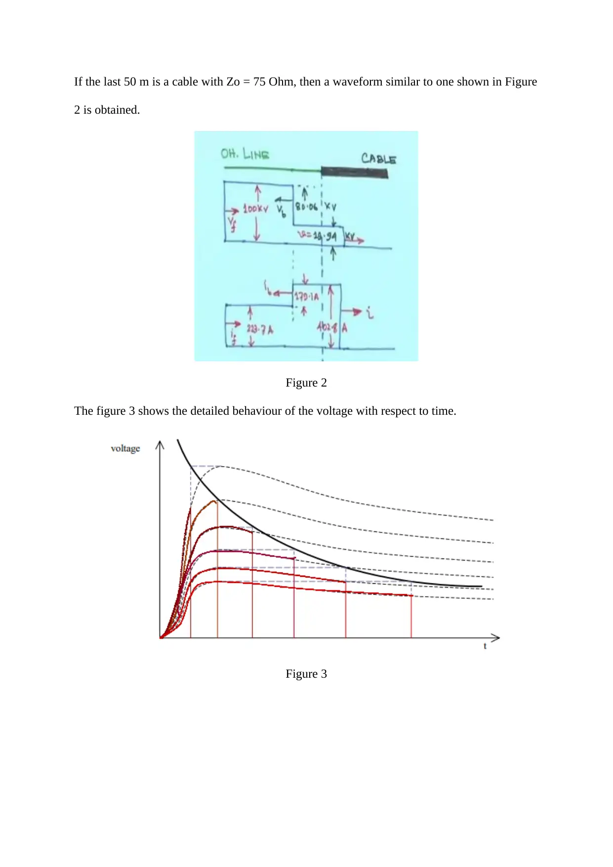
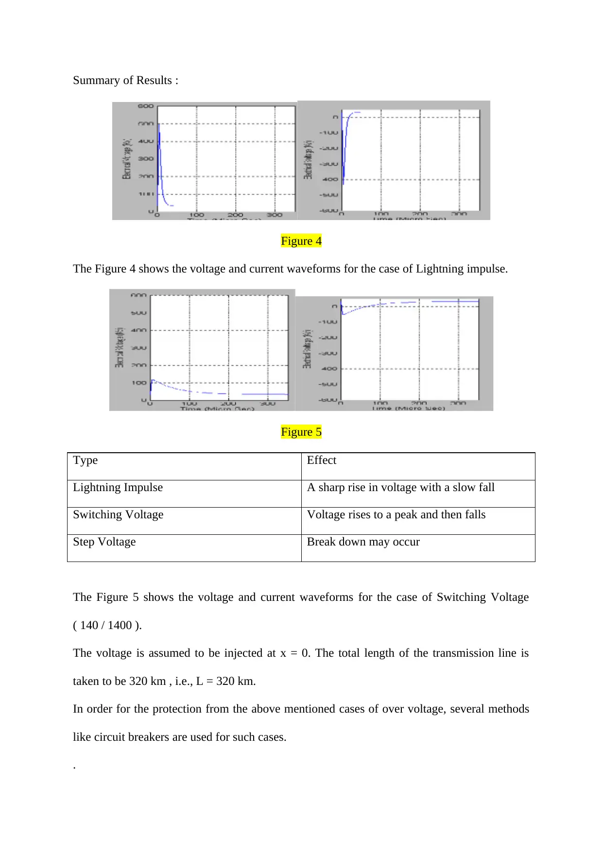
This project report focuses on the simulation of switching impulses on an EHV transmission line between Jubail and Riyadh. The study investigates the behavior of voltage and current during transient conditions, considering lightning, switching, and step impulses. The report utilizes the Alternative Transient Program (ATP) software, an EMTP variant, to model and analyze the transmission line. It explores the effects of different impulse types on the line, including the voltage and current waveforms. The project includes model input data, expected output parameters, a case study, and detailed results and analysis. The findings highlight the importance of understanding transient behavior for designing insulation and electrical clearance requirements in HV transmission lines and the role of protection methods like circuit breakers. The report also covers the effects of lightning impulse, switching voltage, and step voltage on the transmission line and provides a summary of the results, including voltage and current waveforms for different impulse scenarios. The study emphasizes the impact of overvoltage and the need for effective mitigation strategies to ensure power system reliability.
Document Page
Electronics
Electrical power
Student Name –
Student ID –
The lightning impulse may be 1.2 by 50 micro seconds and a switching impulse may be 250
by 2500 micro second and a DC voltage may also be there. The current carrying capacity
may be reduced because of the dielectric losses. An over voltage may be due to an
interruption of the capacitance currents because of switching. The lightning impulse can give
a current which will lead to building up of a voltage due to impedance of the conductor. The
current as well as the voltage , both show travelling wave behaviour. The lightning impulse
as well as switching voltage , both show travelling wave behaviour with a steep wave front.
In case of lightning impulse, a unidirectional voltage is observed which rises fastly to a
maximum value and then falls slowly.
Input Data :
The line is not compensated.
Peak Van 600 kV
Load Impedance , Z 0.5 Zo, Zo, 0.75 Zo, infinity ( Zo = 260
Ohm ) Hence, Z = 130 Ohm, 260 Ohm, 195
Ohm and infinity
For the travelling wave behaviour study, the values of R and G are equal to zero ( lossless
line ). A sudden connection to the voltage source, doesn’t energise the whole line
instantaneously. The voltage wave thus travels from source end to the receiver end.
tabler-icon-diamond-filled.svg

Paraphrase This Document

Need a fresh take? Get an instant paraphrase of this document with our AI Paraphraser
Document Page
While determination of the requirements of insulation and electrical clearance requirement
for designing the HV ( high voltage ) transmission lines , there are 3 types of voltage
considerations to be taken into account. One is lightning impulse voltage ( which shows
maximum voltage value and largest rate of rise of voltage ), other is switching voltage and
last is step voltage. Any over voltage due to lightning or switching surge must be discharged.
A break down may occur in case of step voltage.
The various possible cases are shown in Figure 1 for Lightning impulse ( 10 kHz – 3 MHz ).
Figure 1
Document Page
If the last 50 m is a cable with Zo = 75 Ohm, then a waveform similar to one shown in Figure
2 is obtained.
Figure 2
The figure 3 shows the detailed behaviour of the voltage with respect to time.
Figure 3
Document Page
Summary of Results :
Figure 4
The Figure 4 shows the voltage and current waveforms for the case of Lightning impulse.
Figure 5
Type Effect
Lightning Impulse A sharp rise in voltage with a slow fall
Switching Voltage Voltage rises to a peak and then falls
Step Voltage Break down may occur
The Figure 5 shows the voltage and current waveforms for the case of Switching Voltage
( 140 / 1400 ).
The voltage is assumed to be injected at x = 0. The total length of the transmission line is
taken to be 320 km , i.e., L = 320 km.
In order for the protection from the above mentioned cases of over voltage, several methods
like circuit breakers are used for such cases.
.
tabler-icon-diamond-filled.svg

Paraphrase This Document

Need a fresh take? Get an instant paraphrase of this document with our AI Paraphraser
Document Page
chevron_up_icon
1 out of 5
circle_padding
hide_on_mobile
zoom_out_icon
[object Object]