SmartIdea Network: Switching Technologies Configuration Report

Verified

Added on  2022/08/18

|35
|3345
|33
Practical Assignment
AI Summary
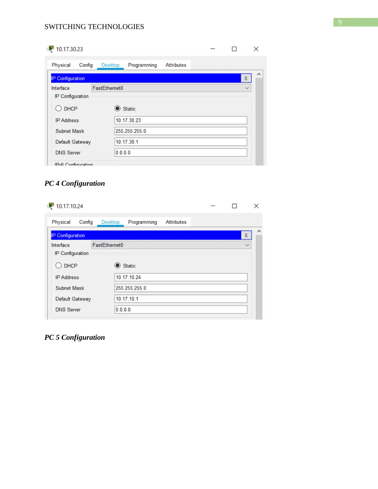
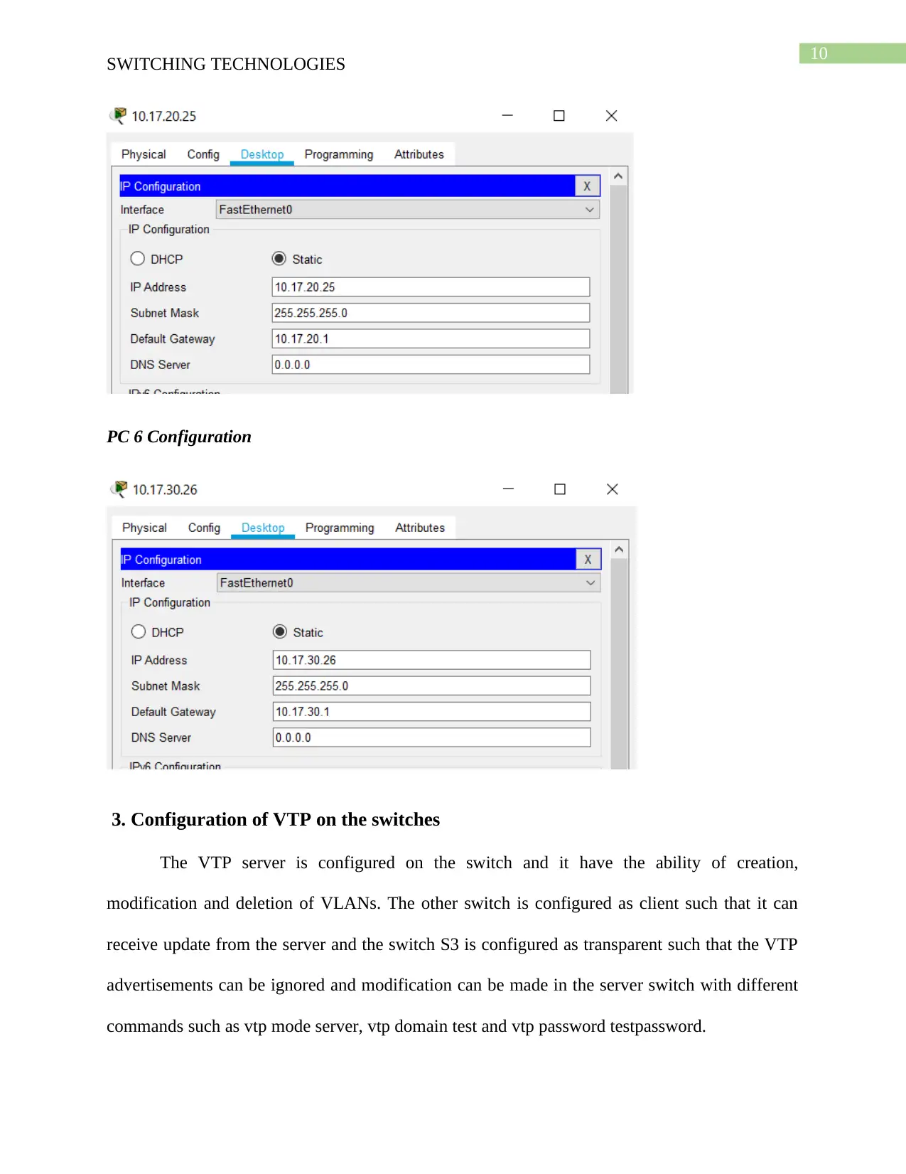
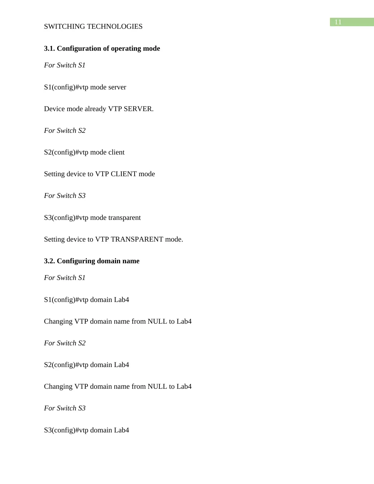
This assignment report details the configuration of switching technologies, specifically focusing on VLANs and VTPs, for the SmartIdea company network. The report covers the basic configurations of switches, including hostname setup, EXEC mode password, console and VTY passwords. It then moves on to configuring Ethernet interfaces on PCs with IP addresses and default gateways, followed by the implementation of VTP on the switches, including setting the operating mode, domain name, and password. Furthermore, the configuration of VLANs on the VTP server and the assignment of switch ports to VLANs are explained. The report also includes the configuration of trunk ports, native VLANs, and management interface addresses on the switches. Finally, the report provides proof of successful host communication within the same VLAN through ping tests and includes screenshots of the ping commands. The configurations are based on the provided addressing table and port assignments, ensuring proper network segmentation and functionality.
Document Page
Running head: SWITCHING TECHNOLOGIES
Switching Technologies
Name of the Student
Name of the University
Author’s Note
tabler-icon-diamond-filled.svg

Paraphrase This Document

Need a fresh take? Get an instant paraphrase of this document with our AI Paraphraser
Document Page
1
SWITCHING TECHNOLOGIES
Table of Contents
Network Diagram............................................................................................................................4
1. Basic Configuration tasks on Switch...........................................................................................4
1.1. Configuration of switches hostname....................................................................................4
1.2. Configuration of EXEC mode password as class.................................................................5
1.3. Configuring password for console connections as cisco......................................................6
1.4. Configuring password for vty connections as cisco.............................................................6
2. Configuration of Ethernet interfaces on PC1, PC2, PC3, PC4, PC5 and PC6 with IP address
and default gateway.........................................................................................................................7
3. Configuration of VTP on the switches......................................................................................10
3.1. Configuration of operating mode........................................................................................11
3.2. Configuring domain name..................................................................................................11
3.3. Configuring VTP password................................................................................................12
4. Configuration of VLAN............................................................................................................12
4.1. Configuring VLANs on VTP server...................................................................................13
4.2. Assigning switch port to VLANs on the switches..............................................................13
5. Configuration of trunk and management interface address on the switches.............................15
5.1. Configuration of trunk and native VLAN on trunk ports...................................................15
5.2. Configuration of management interface address................................................................16
6. Prove of hosts on same VLAN are able to ping each other.......................................................17
Document Page
2
SWITCHING TECHNOLOGIES
6.1. Screenshot of ping command..............................................................................................17
Bibliography..................................................................................................................................20
Appendix........................................................................................................................................23
Document Page
3
SWITCHING TECHNOLOGIES
Table 1
Device Interface IP Address Subnet Mask Default Gateway
S1 VLAN 99 10.17.99.11 255.255.255.0 N/A
S2 VLAN 99 10.17.99.12 255.255.255.0 N/A
S3 VLAN 99 10.17.99.13 255.255.255.0 N/A
PC1 NIC 10.17.10.21 255.255.255.0 10.17.10.1
PC2 NIC 10.17.20.22 255.255.255.0 10.17.20.1
PC3 NIC 10.17.30.23 255.255.255.0 10.17.30.1
PC4 NIC 10.17.10.24 255.255.255.0 10.17.10.1
PC5 NIC 10.17.20.25 255.255.255.0 10.17.20.1
PC6 NIC 10.17.30.26 255.255.255.0 10.17.30.1
Table 2
Ports Assignment Network
Fa0/1 - 0/5 802.1q Trunks (Native VLAN 99) 10.17.99.0 /24
Fa0/6 - 0/10 VLAN 30 - Guest (Default) 10.17.30.0 /24
Fa0/11 - 0/17 VLAN 10 - IT 10.17.10.0 /24
Fa0/18 - 0/24 VLAN 20 - HR 10.17.20.0 /24
tabler-icon-diamond-filled.svg

Paraphrase This Document

Need a fresh take? Get an instant paraphrase of this document with our AI Paraphraser
Document Page
4
SWITCHING TECHNOLOGIES
Network Diagram
1. Basic Configuration tasks on Switch
For performing the basic switch configuration the hostname of the switch is needed to be
renamed and the DNS lookup is needed to be disabled. The EXEC mode is needed to be entered
and a password is needed to be set for increasing the security of the network device. A password
is also needed to be configured for the console connection and vty connection such that the
configuration cannot be accessed by unauthorized personnel and the configurations are secured.
1.1. Configuration of switches hostname
For Switch S1
Switch>enable
Switch#configure terminal
Document Page
5
SWITCHING TECHNOLOGIES
Enter configuration commands, one per line. End with CNTL/Z.
Switch(config)#hostname S1
For Switch S2
Switch>enable
Switch#configure terminal
Enter configuration commands, one per line. End with CNTL/Z.
Switch(config)#hostname S2
For Switch S3
Switch>enable
Switch#configure terminal
Enter configuration commands, one per line. End with CNTL/Z.
Switch(config)#hostname S3
1.2. Configuration of EXEC mode password as class
For Switch S1
S1(config)#enable secret class
For Switch S2
S2(config)#enable secret class
For Switch S3
S2(config)#enable secret class
Document Page
6
SWITCHING TECHNOLOGIES
1.3. Configuring password for console connections as cisco
For Switch S1
S1(config)#no ip domain-lookup
S1(config)#line console 0
S1(config-line)#password cisco
S1(config-line)#login
For Switch S2
S2(config)#no ip domain-lookup
S2(config)#line console 0
S2(config-line)#password cisco
S2(config-line)#login
For Switch S3
S3(config)#no ip domain-lookup
S3(config)#line console 0
S3(config-line)#password cisco
S3(config-line)#login
1.4. Configuring password for vty connections as cisco
For Switch S1
S1(config-line)#line vty 0 15
tabler-icon-diamond-filled.svg

Paraphrase This Document

Need a fresh take? Get an instant paraphrase of this document with our AI Paraphraser
Document Page
7
SWITCHING TECHNOLOGIES
S1(config-line)#password cisco
S1(config-line)#login
S1(config-line)#end
For Switch S2
S2(config-line)#line vty 0 15
S2(config-line)#password cisco
S2(config-line)#login
S2(config-line)#end
For Switch S3
S3(config-line)#line vty 0 15
S3(config-line)#password cisco
S3(config-line)#login
S3(config-line)#end
2. Configuration of Ethernet interfaces on PC1, PC2, PC3, PC4, PC5 and PC6 with
IP address and default gateway
The Ethernet interface of the PC are configured following the IP addressing plan and they
are connected with the right port such they can communicate with the VLAN and send and
receive data packets within the network.
PC1 Configuration
Document Page
8
SWITCHING TECHNOLOGIES
PC2 Configuration
PC3 Configuration
Document Page
9
SWITCHING TECHNOLOGIES
PC 4 Configuration
PC 5 Configuration
tabler-icon-diamond-filled.svg

Paraphrase This Document

Need a fresh take? Get an instant paraphrase of this document with our AI Paraphraser
Document Page
10
SWITCHING TECHNOLOGIES
PC 6 Configuration
3. Configuration of VTP on the switches
The VTP server is configured on the switch and it have the ability of creation,
modification and deletion of VLANs. The other switch is configured as client such that it can
receive update from the server and the switch S3 is configured as transparent such that the VTP
advertisements can be ignored and modification can be made in the server switch with different
commands such as vtp mode server, vtp domain test and vtp password testpassword.
Document Page
11
SWITCHING TECHNOLOGIES
3.1. Configuration of operating mode
For Switch S1
S1(config)#vtp mode server
Device mode already VTP SERVER.
For Switch S2
S2(config)#vtp mode client
Setting device to VTP CLIENT mode
For Switch S3
S3(config)#vtp mode transparent
Setting device to VTP TRANSPARENT mode.
3.2. Configuring domain name
For Switch S1
S1(config)#vtp domain Lab4
Changing VTP domain name from NULL to Lab4
For Switch S2
S2(config)#vtp domain Lab4
Changing VTP domain name from NULL to Lab4
For Switch S3
S3(config)#vtp domain Lab4
chevron_up_icon
1 out of 35
circle_padding
hide_on_mobile
zoom_out_icon
[object Object]