A Detailed Structural Analysis of the Sydney Harbour Bridge
VerifiedAdded on 2020/05/08
|21
|4345
|359
Report
AI Summary
This report provides a comprehensive structural analysis of the Sydney Harbour Bridge, covering its history, design, and the engineering principles behind its construction. The analysis includes detailed calculations of dead load, live load, and the effects of wind and temperature. The report explores the support and reaction forces, shear force diagrams, bending moment diagrams, and bending and shear stress distributions across critical sections. It also examines the bridge's balancing nature using the elastic curve equation and discusses miscellaneous issues related to the bridge's structural integrity. The report aims to analyze the bridge's structural behavior using assumed parameters and comparing the old structural analysis methods with the current methods.
Harbour Bridge
1 | P a g e
Mechanics of Structure
1 | P a g e
Mechanics of Structure
Paraphrase This Document
Need a fresh take? Get an instant paraphrase of this document with our AI Paraphraser
Harbour Bridge
Executive Summery
This assignment analyses one of the remarkable structure made by human kind, and it is known
as Harbour Bridge Sydney which is situated in Australia. We have given various assumptions
that how we have measured the different parameter, a brief history and property of this particular
bridge. Further we have analyzed the stress, strain, shear force diagram and bending moment
diagram based on our assumed parameter. We have also analyzed the balancing nature of the
bridge by using elastic curve equation, assumption of dead and alive load were also calculated
according to the traffic and material consumed. Further wind load and temperature effect were
also analyzed specially for this bridge.
2 | P a g e
Harbour Bridge
Contents
Introduction......................................................................................................................................4
Dead Load....................................................................................................................................6
Live loads.....................................................................................................................................6
Support and reaction forces.........................................................................................................7
Calculating shear force................................................................................................................9
Calculating bending moment diagram.......................................................................................10
Bending stress distribution across critical section.....................................................................12
Shear stress distribution across critical section.........................................................................13
Maximum deflection using elastic curve method......................................................................14
Miscellaneous Issue...................................................................................................................17
Conclusion,................................................................................................................................17
Introduction
3 | P a g e
⊘ This is a preview!⊘
Do you want full access?
Subscribe today to unlock all pages.
Trusted by 1+ million students worldwide
Harbour Bridge
As the time proceeds, Science and technology both developing simultaneously with adding
knowledge and experience in the entire engineering related stream. Analysis of structure is also
one of them. This field becomes more accurate and structural behaviour becomes more
predictable. In the same ways the development of organised society also developed and same
way knowledge of their construction also emerged as important field. This results more
communication and complex traffic system which include small and large bridges, roads and
minimum distance approach phenomena. The gain in knowledge and experience also enhanced
the support in safety and loads of traffic passing through theses bridges.
Once again we have to analyse one the old but famous bridge with my structural analysis point
of view. The motivation and objective behind this work is directly comes from O’Connor 2017
statement, and it is “The steps leading to the introduction of new design loads and other major
changes in codes of practice must include a comparison with older codes and some study of the
performance and strength of existing structures” (O Connor, 2017).”
As stated earlier we have selected a bridge for our analysis purposes, and the bridge we have
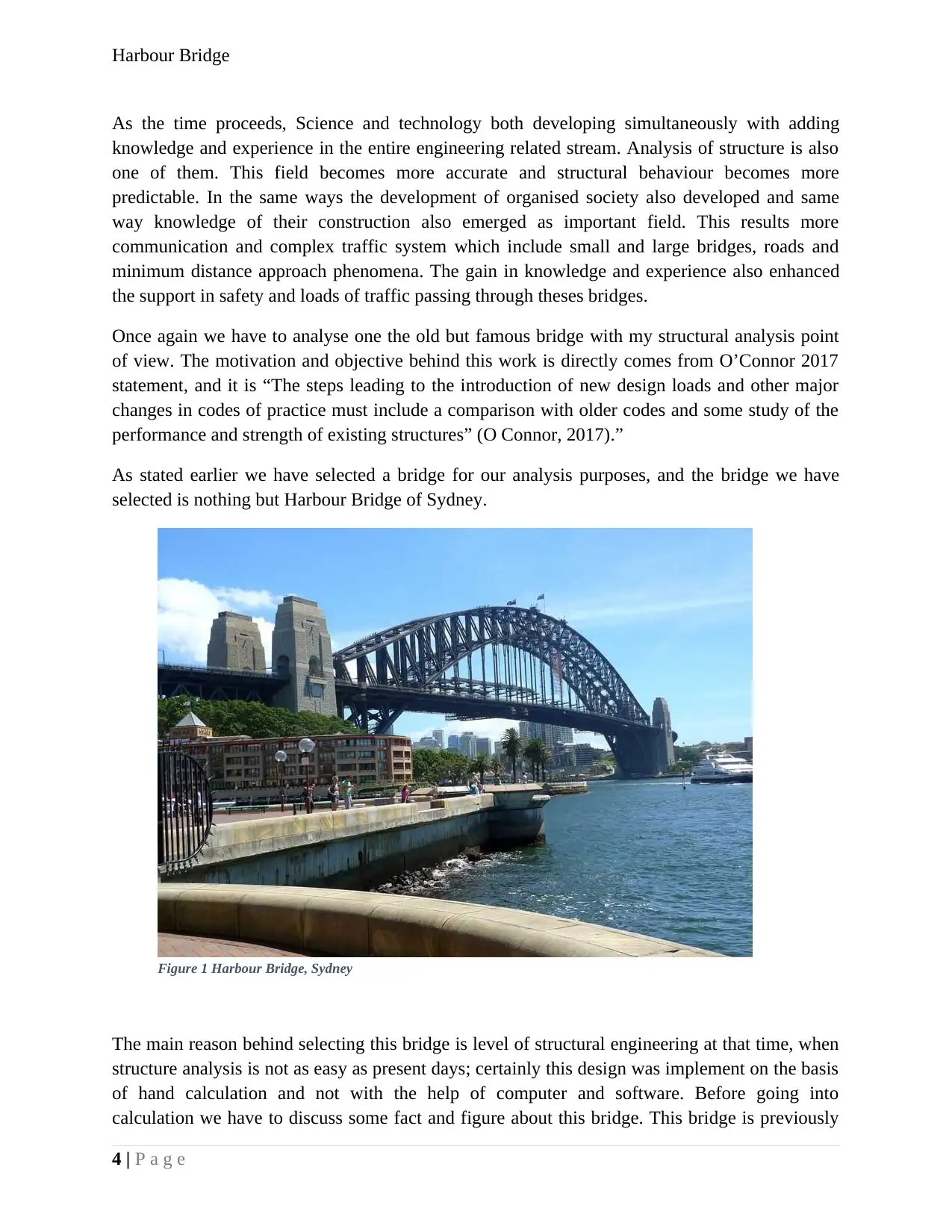
selected is nothing but Harbour Bridge of Sydney.
The main reason behind selecting this bridge is level of structural engineering at that time, when
structure analysis is not as easy as present days; certainly this design was implement on the basis
of hand calculation and not with the help of computer and software. Before going into
calculation we have to discuss some fact and figure about this bridge. This bridge is previously
4 | P a g e
Figure 1 Harbour Bridge, Sydney
As the time proceeds, Science and technology both developing simultaneously with adding
knowledge and experience in the entire engineering related stream. Analysis of structure is also
one of them. This field becomes more accurate and structural behaviour becomes more
predictable. In the same ways the development of organised society also developed and same
way knowledge of their construction also emerged as important field. This results more
communication and complex traffic system which include small and large bridges, roads and
minimum distance approach phenomena. The gain in knowledge and experience also enhanced
the support in safety and loads of traffic passing through theses bridges.
Once again we have to analyse one the old but famous bridge with my structural analysis point
of view. The motivation and objective behind this work is directly comes from O’Connor 2017
statement, and it is “The steps leading to the introduction of new design loads and other major
changes in codes of practice must include a comparison with older codes and some study of the
performance and strength of existing structures” (O Connor, 2017).”
As stated earlier we have selected a bridge for our analysis purposes, and the bridge we have
selected is nothing but Harbour Bridge of Sydney.
The main reason behind selecting this bridge is level of structural engineering at that time, when
structure analysis is not as easy as present days; certainly this design was implement on the basis
of hand calculation and not with the help of computer and software. Before going into
calculation we have to discuss some fact and figure about this bridge. This bridge is previously
4 | P a g e
Figure 1 Harbour Bridge, Sydney
Paraphrase This Document
Need a fresh take? Get an instant paraphrase of this document with our AI Paraphraser
Harbour Bridge
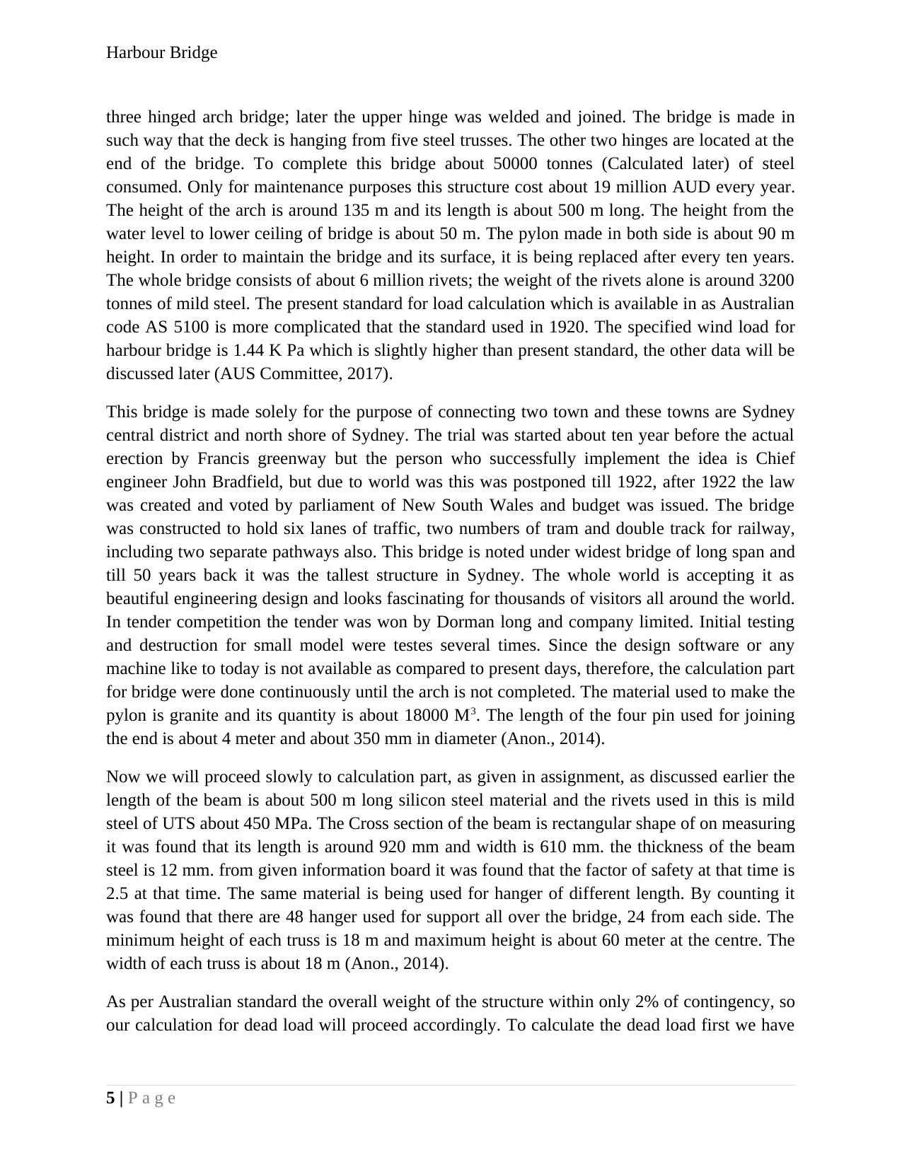
three hinged arch bridge; later the upper hinge was welded and joined. The bridge is made in
such way that the deck is hanging from five steel trusses. The other two hinges are located at the
end of the bridge. To complete this bridge about 50000 tonnes (Calculated later) of steel
consumed. Only for maintenance purposes this structure cost about 19 million AUD every year.
The height of the arch is around 135 m and its length is about 500 m long. The height from the
water level to lower ceiling of bridge is about 50 m. The pylon made in both side is about 90 m
height. In order to maintain the bridge and its surface, it is being replaced after every ten years.
The whole bridge consists of about 6 million rivets; the weight of the rivets alone is around 3200
tonnes of mild steel. The present standard for load calculation which is available in as Australian
code AS 5100 is more complicated that the standard used in 1920. The specified wind load for
harbour bridge is 1.44 K Pa which is slightly higher than present standard, the other data will be
discussed later (AUS Committee, 2017).
This bridge is made solely for the purpose of connecting two town and these towns are Sydney
central district and north shore of Sydney. The trial was started about ten year before the actual
erection by Francis greenway but the person who successfully implement the idea is Chief
engineer John Bradfield, but due to world was this was postponed till 1922, after 1922 the law
was created and voted by parliament of New South Wales and budget was issued. The bridge
was constructed to hold six lanes of traffic, two numbers of tram and double track for railway,
including two separate pathways also. This bridge is noted under widest bridge of long span and
till 50 years back it was the tallest structure in Sydney. The whole world is accepting it as
beautiful engineering design and looks fascinating for thousands of visitors all around the world.
In tender competition the tender was won by Dorman long and company limited. Initial testing
and destruction for small model were testes several times. Since the design software or any
machine like to today is not available as compared to present days, therefore, the calculation part
for bridge were done continuously until the arch is not completed. The material used to make the
pylon is granite and its quantity is about 18000 M3. The length of the four pin used for joining
the end is about 4 meter and about 350 mm in diameter (Anon., 2014).
Now we will proceed slowly to calculation part, as given in assignment, as discussed earlier the
length of the beam is about 500 m long silicon steel material and the rivets used in this is mild
steel of UTS about 450 MPa. The Cross section of the beam is rectangular shape of on measuring
it was found that its length is around 920 mm and width is 610 mm. the thickness of the beam
steel is 12 mm. from given information board it was found that the factor of safety at that time is
2.5 at that time. The same material is being used for hanger of different length. By counting it
was found that there are 48 hanger used for support all over the bridge, 24 from each side. The
minimum height of each truss is 18 m and maximum height is about 60 meter at the centre. The
width of each truss is about 18 m (Anon., 2014).
As per Australian standard the overall weight of the structure within only 2% of contingency, so
our calculation for dead load will proceed accordingly. To calculate the dead load first we have
5 | P a g e
Harbour Bridge
to figure-out material used in making this bridge, total load in distributed on four different
bearing from each corners at the sides, the rated capacity for thrust bearing is given as 20 kN.
Dead Load
The main material used in bridge are Asphalt, Concrete, stone, coke, including floating, Granite,
Steel rolled, Steel cast, Wrought-iron, Cast-iron, Timber, Ironbark or Grey Gum, Rails and
fastenings, Guard rails and fastenings, we the specific density of each material, If we calculate
the total length. From specification given on bridge it was found that on each meter 105 tons of
steel is used
Therefore,
Total load capacity of bearing = 200,000 kN x 4 = 800,000 = 800000 kN.
The total steel weight = 105 x 500 = 52500 tons
As per Australian standard for load the factor of safety for ultimate limit state γ f3 = 1.1 and γfl =
1.05 then total force will be calculated as
52500 x 1.1 x 1.05 = 60637 KN.
The bridge is completely balance therefore 60637 / 4 = 15160 KN on each of the bearing, In
spite of this steel structure the other materials are not used as huge as steel, and bearing capacity
is much greater than steel load, minor load are not assumed in this calculation.
Live loads
The live load consists of load due traffic on the bridge, Impact due to deck system, load due to
wind and load due to temperature.
As per standard limit the specified limit is 9kN / meter, we have estimated the length and width
of bridge is about 50 x 500 m. Then total uniform distributed load for the traffic. The notional
length width is 3.8 meter specified, in this condition there are thirteen notional lanes is available.
The rail lane is considered as full load lane and rest eleven lane is supposed to be carrying 1/3 of
UDL.
Full load lane = 9 * 500 * 2 = 9000 KN
Rest eleven lane = 3 * 11* 500 = 16500 KN
Total Load = 9000 + 16500 = 25500 KN
6 | P a g e
⊘ This is a preview!⊘
Do you want full access?
Subscribe today to unlock all pages.
Trusted by 1+ million students worldwide
Harbour Bridge
After multiplying factor of safety = 25500 x 1.1x1.5 = 29452 KN
After adding the dead load = 29452 + 60637 = 900900 KN
This is still less than 800000 KN
Now I have to consider temperature and wind
It is clear that there no hindrance in thermal expansion upward, we also know that the coefficient
for thermal expansion for steel is α = 12 * 10-6 / OC. It assumed that maximum temperature
difference is 25 oC in Sydney.
Δ L=12 x 10−6 x 135 x 25
On calculation, the arch of the bridge can expand vertically up to 40.5 mm.
The horizontal expansion can be calculated as given below
Δ L=12 x 10−6 x 500 x 25=0.15 = 150 mm
From specification, it was found that the deck can be expanded by 400 mm; the calculated
expansion is quit less than the allowed expansion.
As per Australian standard load the allowable air pressure is calculated with the formula
Vd = Sg x Vs
For specific place Sydney, the wind load Vd is specified as = 55 kN/cubic meter.
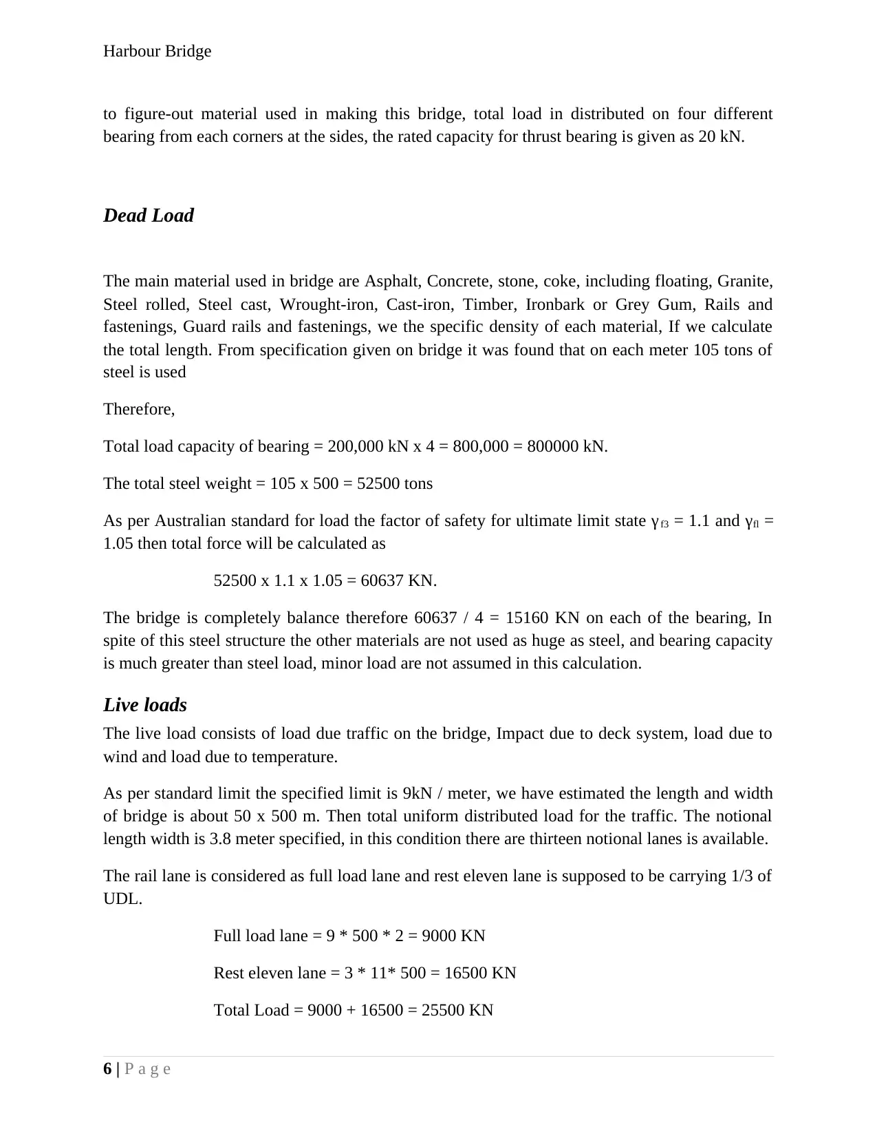
Support and reaction forces
Near the pylon we can see that each support is hinged at
an angle of around 45o. In such condition all the loads
trying to make the arch in horizontal straight, but it is
supported on hinged approach so all load comes to this
four hinges, we can calculate the total load on each
hinge
7 | P a g e
Figure 2 Hinge support
After multiplying factor of safety = 25500 x 1.1x1.5 = 29452 KN
After adding the dead load = 29452 + 60637 = 900900 KN
This is still less than 800000 KN
Now I have to consider temperature and wind
It is clear that there no hindrance in thermal expansion upward, we also know that the coefficient
for thermal expansion for steel is α = 12 * 10-6 / OC. It assumed that maximum temperature
difference is 25 oC in Sydney.
Δ L=12 x 10−6 x 135 x 25
On calculation, the arch of the bridge can expand vertically up to 40.5 mm.
The horizontal expansion can be calculated as given below
Δ L=12 x 10−6 x 500 x 25=0.15 = 150 mm
From specification, it was found that the deck can be expanded by 400 mm; the calculated
expansion is quit less than the allowed expansion.
As per Australian standard load the allowable air pressure is calculated with the formula
Vd = Sg x Vs
For specific place Sydney, the wind load Vd is specified as = 55 kN/cubic meter.
Support and reaction forces
Near the pylon we can see that each support is hinged at
an angle of around 45o. In such condition all the loads
trying to make the arch in horizontal straight, but it is
supported on hinged approach so all load comes to this
four hinges, we can calculate the total load on each
hinge
7 | P a g e
Figure 2 Hinge support
Paraphrase This Document
Need a fresh take? Get an instant paraphrase of this document with our AI Paraphraser
Harbour Bridge
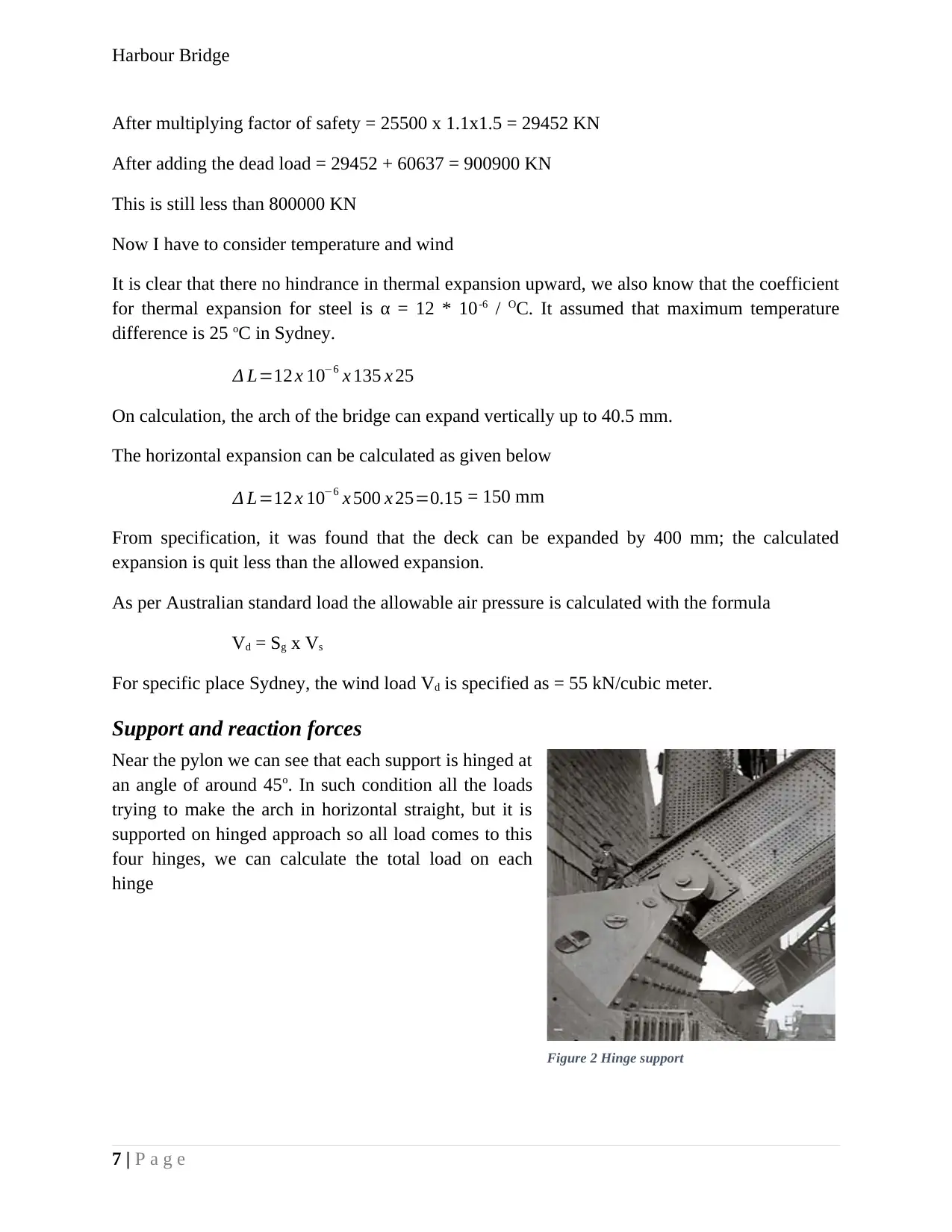
The total concentrated load is considered about 90090 KN,
The height from hinge to the top arch is about 110 m (Total height assumes 135 m, 25 m from
ground to hinge)
Noe we can calculate the load as per figure given below
From figure,
∑ V ↑=0
VA + VB – 900900 KN = 0 (i)
VA + VB = 900900 KN
∑ H ↑=0
HA – HB = 0
∴ HA = HB
250 x 90090 – 500 VB = 0
V B = 250 x 90090
500 =450450 KN
8 | P a g e
900900 KN900900 KN900900 KN900900 KN900900 KN900900 KN900900 KN900900 KN900900 KN900900 KN900900 KN900900 KN900900 KN900900 KN900900 KN900900 KN900900 KN900900 KN
Harbour Bridge
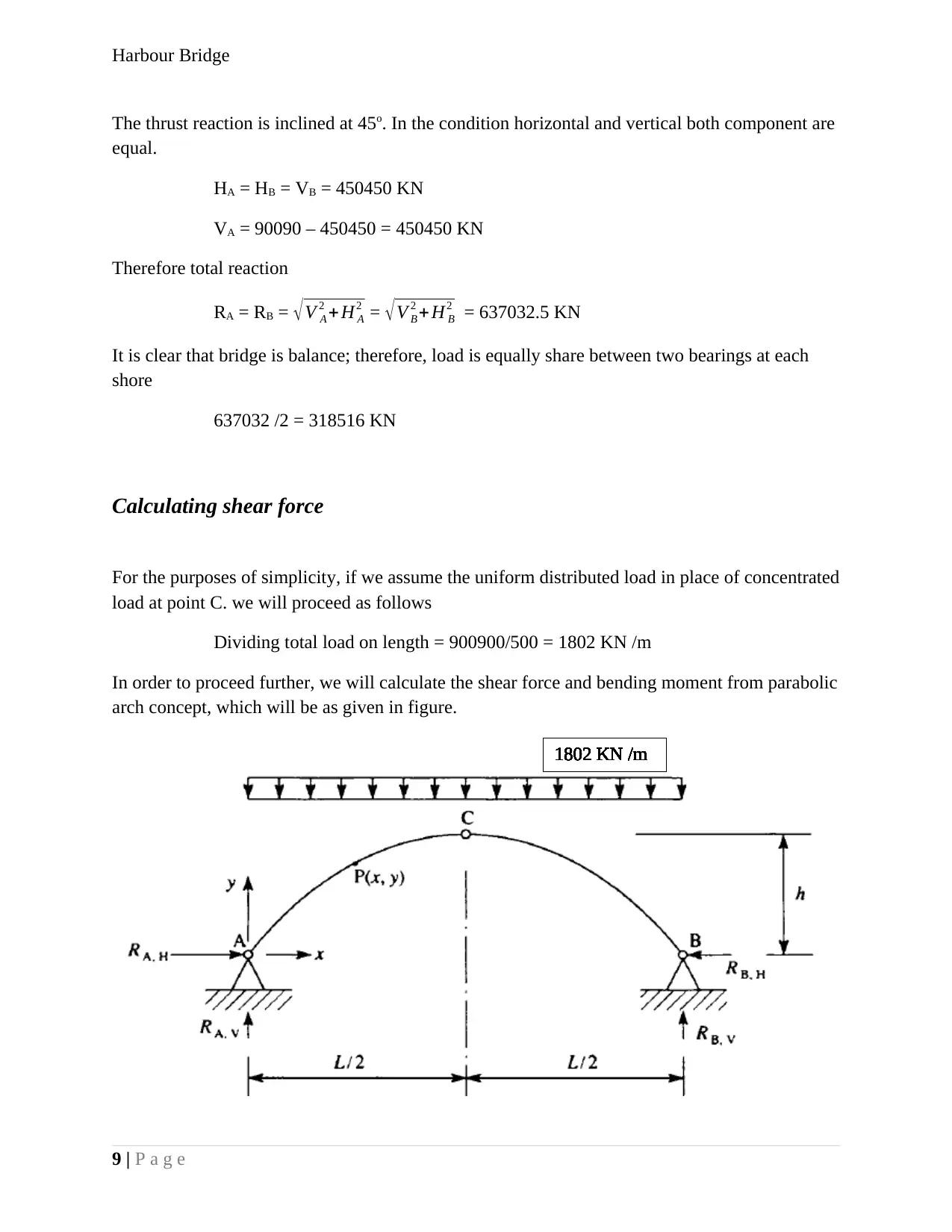
The thrust reaction is inclined at 45o. In the condition horizontal and vertical both component are
equal.
HA = HB = VB = 450450 KN
VA = 90090 – 450450 = 450450 KN
Therefore total reaction
RA = RB = √V A
2 + H A
2 = √V B
2 + H B
2 = 637032.5 KN
It is clear that bridge is balance; therefore, load is equally share between two bearings at each
shore
637032 /2 = 318516 KN
Calculating shear force
For the purposes of simplicity, if we assume the uniform distributed load in place of concentrated
load at point C. we will proceed as follows
Dividing total load on length = 900900/500 = 1802 KN /m
In order to proceed further, we will calculate the shear force and bending moment from parabolic
arch concept, which will be as given in figure.
9 | P a g e
1802 KN /m1802 KN /m1802 KN /m1802 KN /m1802 KN /m1802 KN /m1802 KN /m1802 KN /m1802 KN /m1802 KN /m1802 KN /m1802 KN /m1802 KN /m1802 KN /m1802 KN /m1802 KN /m1802 KN /m1802 KN /m
⊘ This is a preview!⊘
Do you want full access?
Subscribe today to unlock all pages.
Trusted by 1+ million students worldwide
Harbour Bridge
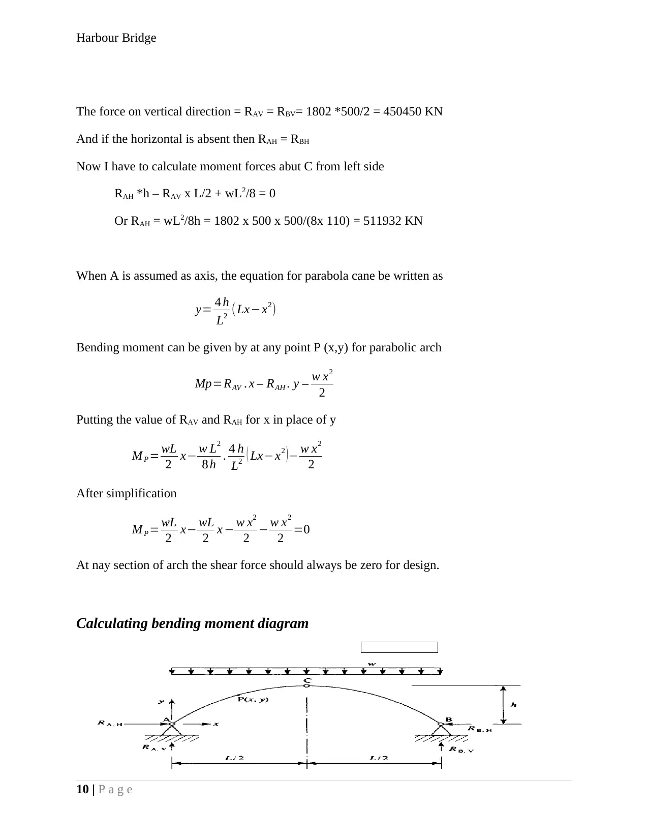
The force on vertical direction = RAV = RBV= 1802 *500/2 = 450450 KN
And if the horizontal is absent then RAH = RBH
Now I have to calculate moment forces abut C from left side
RAH *h – RAV x L/2 + wL2/8 = 0
Or RAH = wL2/8h = 1802 x 500 x 500/(8x 110) = 511932 KN
When A is assumed as axis, the equation for parabola cane be written as
y= 4 h
L2 (Lx−x2)
Bending moment can be given by at any point P (x,y) for parabolic arch
Mp=RAV . x – RAH . y – w x2
2
Putting the value of RAV and RAH for x in place of y
M P = wL
2 x− w L2
8 h . 4 h
L2 ( Lx−x2 )− w x2
2
After simplification
M P = wL
2 x− wL
2 x − w x2
2 − w x2
2 =0
At nay section of arch the shear force should always be zero for design.
Calculating bending moment diagram
10 | P a g e
180218021802180218021802180218021802180218021802180218021802180218021802
Paraphrase This Document
Need a fresh take? Get an instant paraphrase of this document with our AI Paraphraser
Harbour Bridge
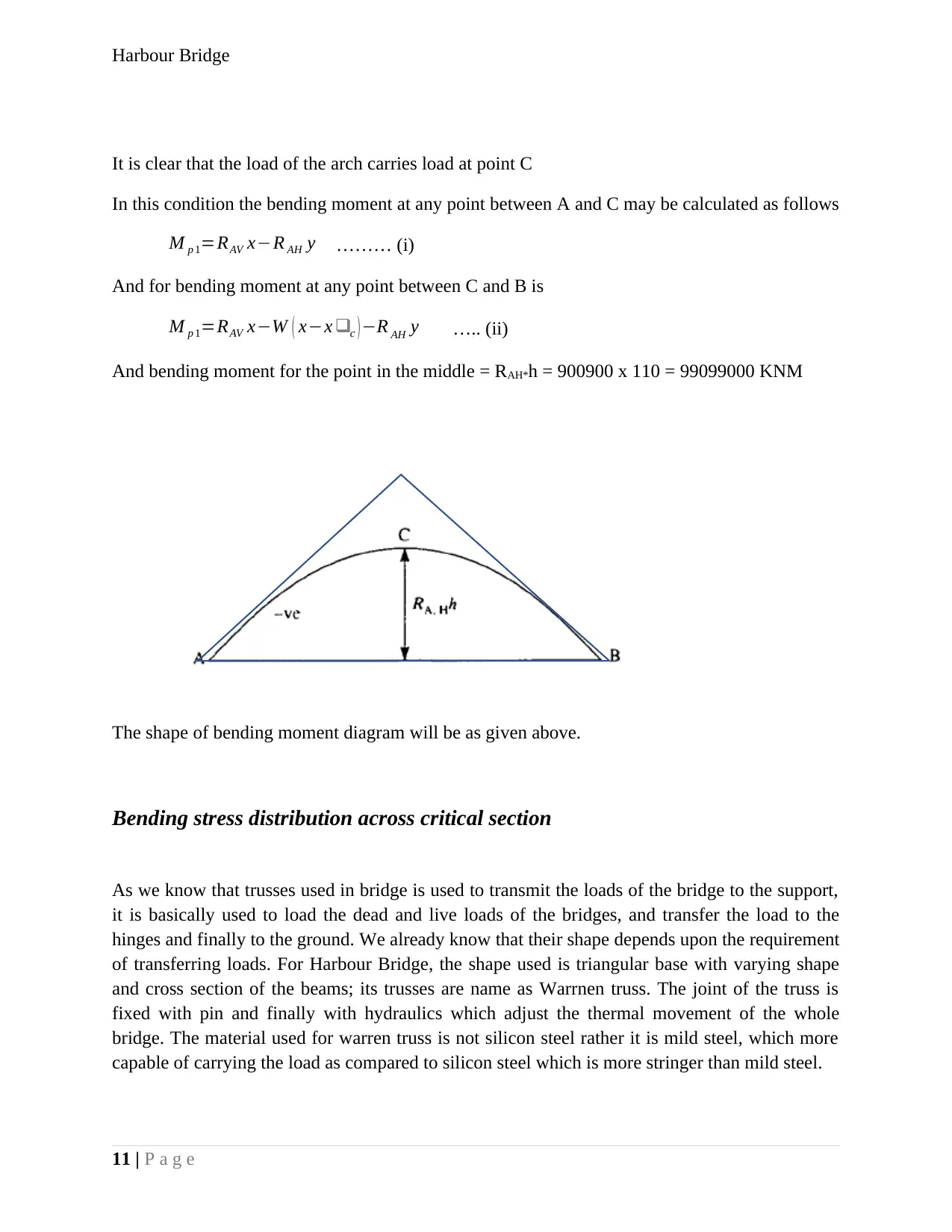
It is clear that the load of the arch carries load at point C
In this condition the bending moment at any point between A and C may be calculated as follows
M p 1=RAV x−R AH y ……… (i)
And for bending moment at any point between C and B is
M p 1=RAV x−W ( x−x ❑c ) −R AH y ….. (ii)
And bending moment for the point in the middle = RAH*h = 900900 x 110 = 99099000 KNM
The shape of bending moment diagram will be as given above.
Bending stress distribution across critical section
As we know that trusses used in bridge is used to transmit the loads of the bridge to the support,
it is basically used to load the dead and live loads of the bridges, and transfer the load to the
hinges and finally to the ground. We already know that their shape depends upon the requirement
of transferring loads. For Harbour Bridge, the shape used is triangular base with varying shape
and cross section of the beams; its trusses are name as Warrnen truss. The joint of the truss is
fixed with pin and finally with hydraulics which adjust the thermal movement of the whole
bridge. The material used for warren truss is not silicon steel rather it is mild steel, which more
capable of carrying the load as compared to silicon steel which is more stringer than mild steel.
11 | P a g e
Harbour Bridge
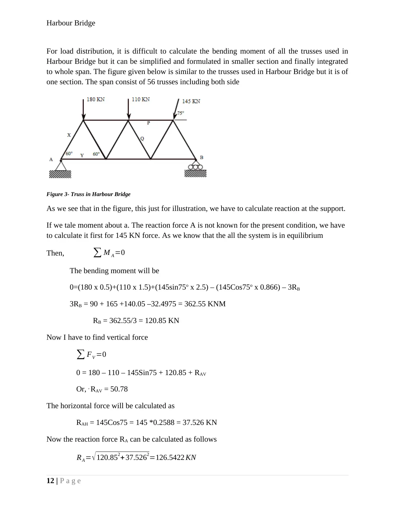
For load distribution, it is difficult to calculate the bending moment of all the trusses used in
Harbour Bridge but it can be simplified and formulated in smaller section and finally integrated
to whole span. The figure given below is similar to the trusses used in Harbour Bridge but it is of
one section. The span consist of 56 trusses including both side
Figure 3- Truss in Harbour Bridge
As we see that in the figure, this just for illustration, we have to calculate reaction at the support.
If we tale moment about a. The reaction force A is not known for the present condition, we have
to calculate it first for 145 KN force. As we know that the all the system is in equilibrium
Then, ∑ M A =0
The bending moment will be
0=(180 x 0.5)+(110 x 1.5)+(145sin75o x 2.5) – (145Cos75o x 0.866) – 3RB
3RB = 90 + 165 +140.05 –32.4975 = 362.55 KNM
RB = 362.55/3 = 120.85 KN
Now I have to find vertical force
∑ FV =0
0 = 180 – 110 – 145Sin75 + 120.85 + RAV
Or, , RAV = 50.78
The horizontal force will be calculated as
RAH = 145Cos75 = 145 *0.2588 = 37.526 KN
Now the reaction force RA can be calculated as follows
RA = √ 120.852+ 37.5262=126.5422 KN
12 | P a g e
⊘ This is a preview!⊘
Do you want full access?
Subscribe today to unlock all pages.
Trusted by 1+ million students worldwide
1 out of 21
Related Documents


Your All-in-One AI-Powered Toolkit for Academic Success.
+13062052269
info@desklib.com
Available 24*7 on WhatsApp / Email
![[object Object]](/_next/static/media/star-bottom.7253800d.svg)
Unlock your academic potential
Copyright © 2020–2026 A2Z Services. All Rights Reserved. Developed and managed by ZUCOL.