Sydney Harbour Bridge: Preliminary and Detailed Design Analysis
VerifiedAdded on 2023/06/08
|17
|2972
|441
Report
AI Summary
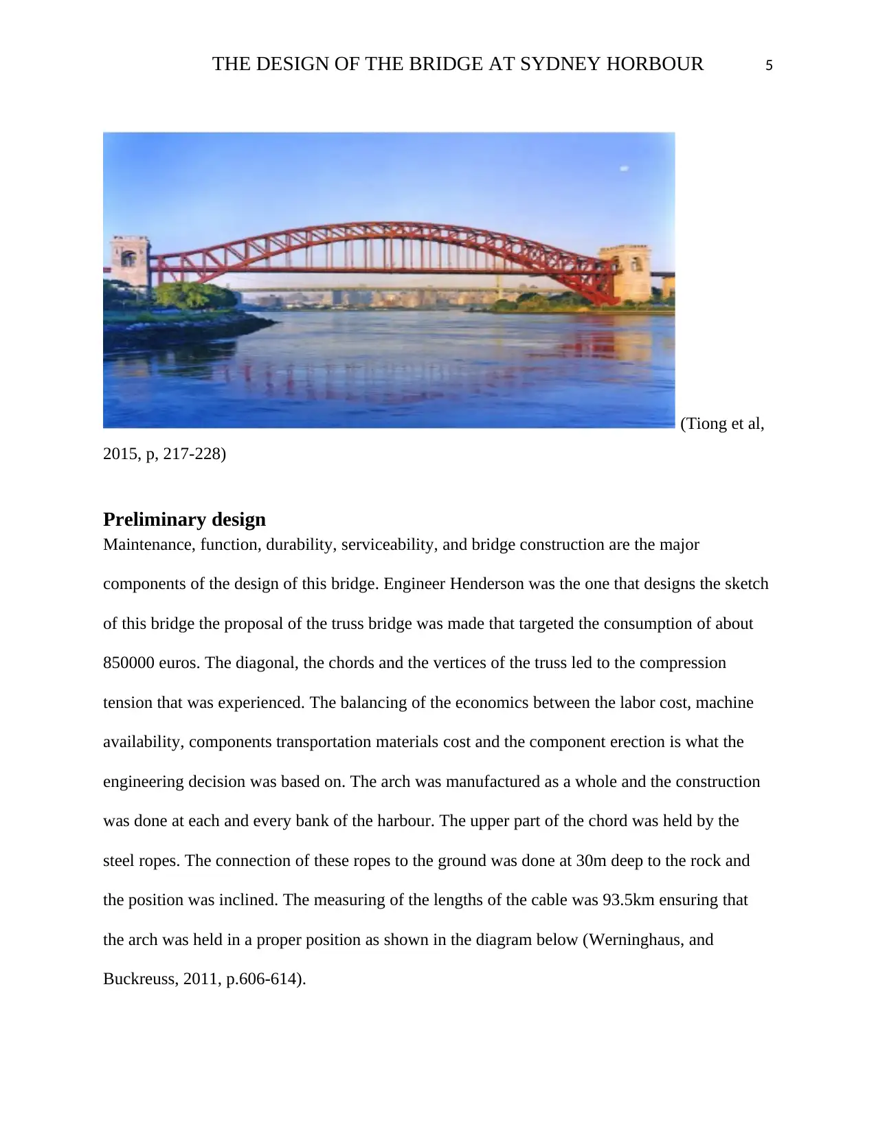
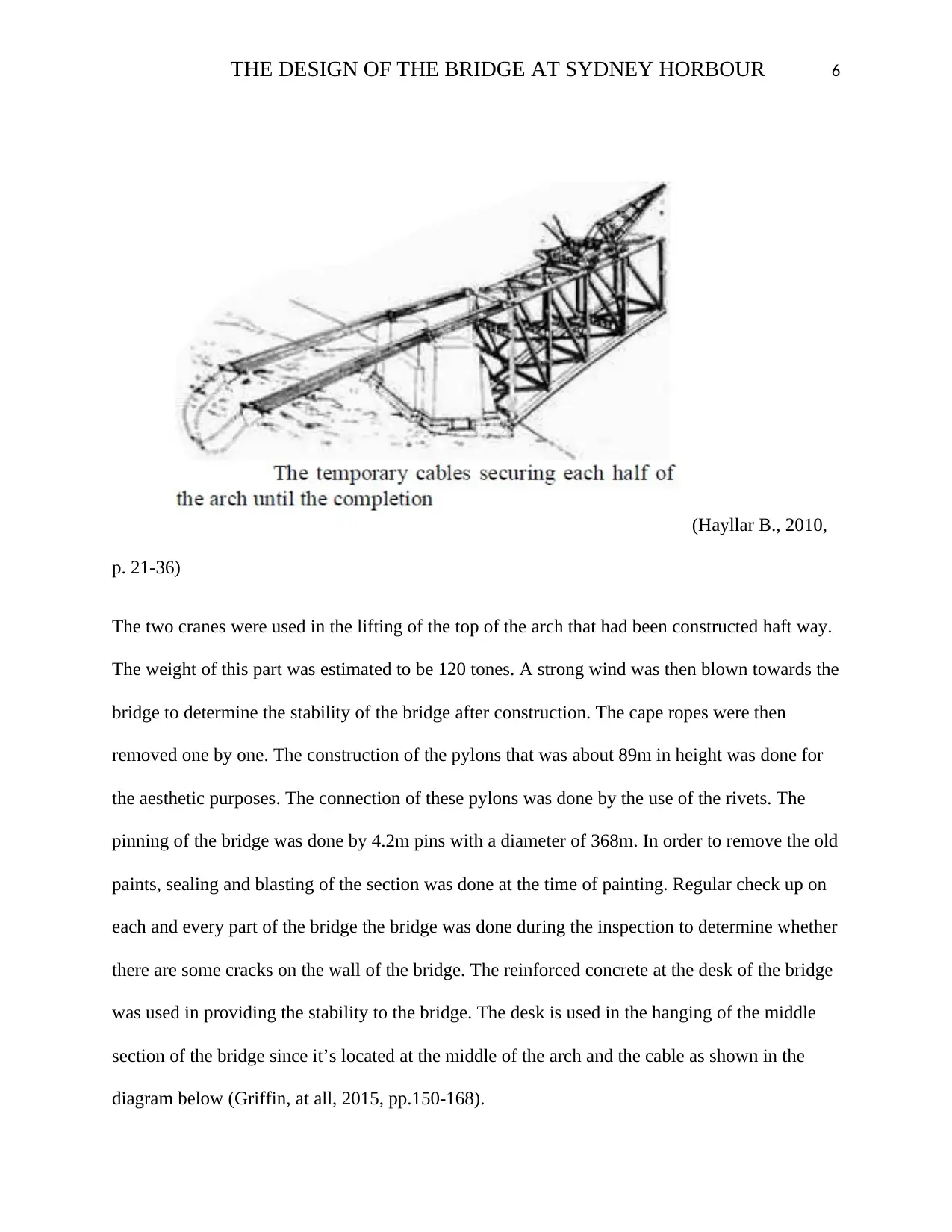
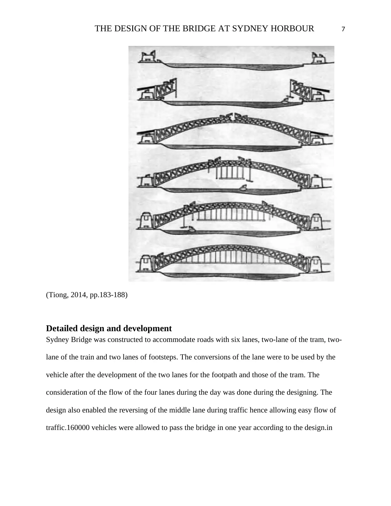
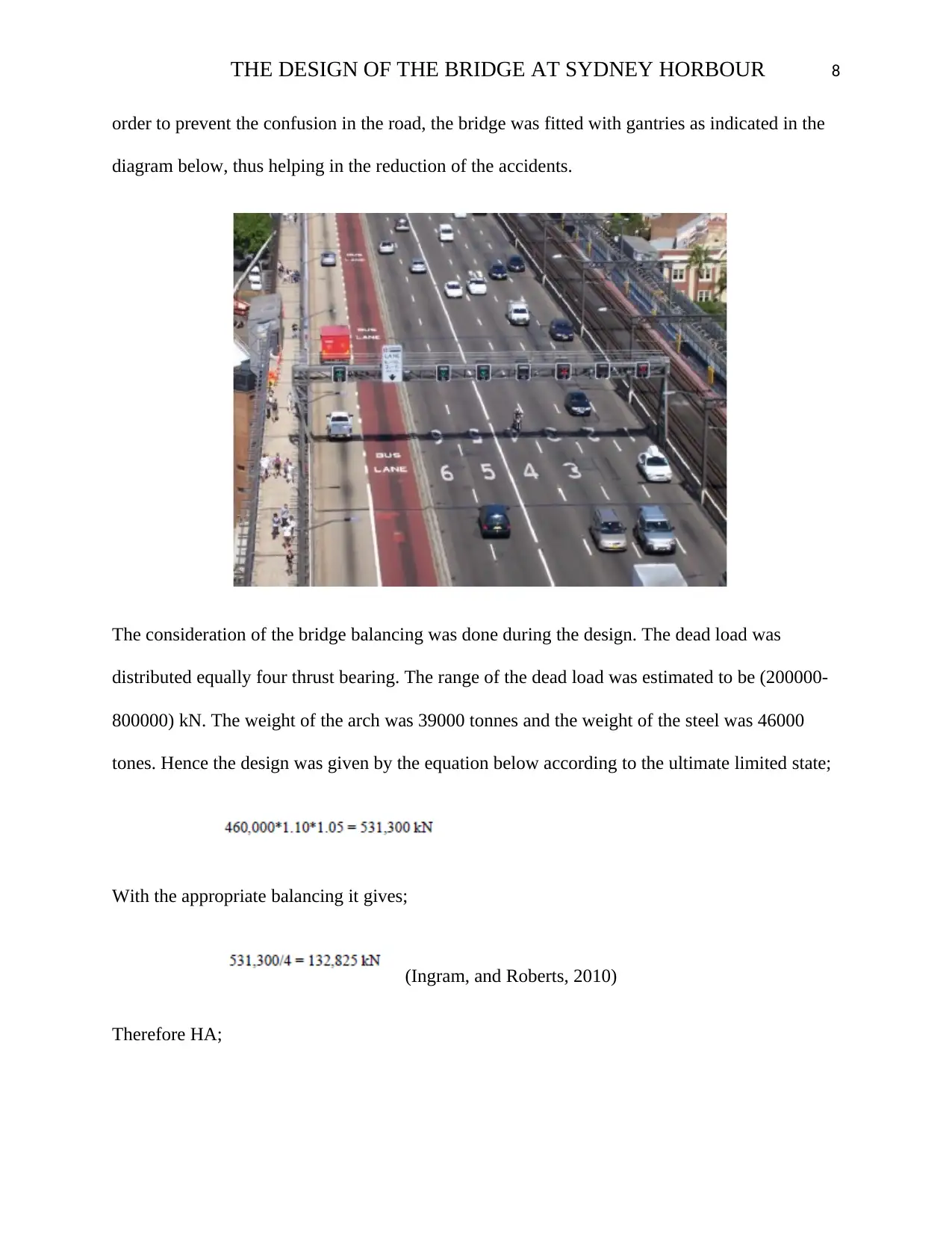
This report provides a comprehensive analysis of the Sydney Harbour Bridge's design and construction process, addressing needs definition, maintenance, feasibility, system operation requirements, functional analysis, system planning, and performance measurement. It examines the preliminary and detailed design phases, system testing, evaluation, validation processes, human factors, and optimizations. The bridge, designed by Dorman Long and Co Ltd under Dr. John Bradfield's supervision, accommodates pedestrians, bicycles, traffic, vehicles, and rails between Sydney's central business district and the North Shore. The report highlights the bridge's design influenced by the Hell Gate Bridge in New York City and its status as one of the tallest and widest long-span bridges globally. The construction process involved building workshops, laying foundations, and using creeper cranes, with granite and concrete used for the face support towers. The design considered traffic flow, load balancing, temperature effects, and wind resistance, ensuring the bridge's stability and durability.

THE DESIGN OF THE BRIDGE AT SYDNEY HORBOUR 1
THE DESIGN OF THE BRIDGE AT SYDNEY HORBOUR
By Name
Course
Instructor
Institution
Location
Date
THE DESIGN OF THE BRIDGE AT SYDNEY HORBOUR
By Name
Course
Instructor
Institution
Location
Date
Paraphrase This Document
Need a fresh take? Get an instant paraphrase of this document with our AI Paraphraser

THE DESIGN OF THE BRIDGE AT SYDNEY HORBOUR 2
Executive summery
The bridge in Sydney is one of the largest bridges in the world. It is abridge that is composed of
the steel and an arch used for holding it. This bridge contains two lane of the tram, two lane of
traffic and two lanes of the train. The bridge is mostly used by the pedestrians, train and
Vehicles. The Bridge composed of the steel, the pylons that used for the support and the deck. It
has span of 503m and height of 134m.The construction has led to several benefits like, creation
of jobs as many people were involved in the maintenance and construction of the bridge, so
many new businesses were developed as a result the construction of this bridge, proper sources
of finance, there were many jobs that led to numerous sources of finance, amongst other benefits.

THE DESIGN OF THE BRIDGE AT SYDNEY HORBOUR 3
Contents
Executive summery.....................................................................................................................................2
Contents.......................................................................................................................................................3
Introduction.................................................................................................................................................4
Preliminary design.......................................................................................................................................5
Detailed design and development................................................................................................................7
Planning of the System..........................................................................................................................12
System test evaluation validation and optimization...................................................................................12
Conclusion.................................................................................................................................................13
Recommendation.......................................................................................................................................15
References.................................................................................................................................................16
⊘ This is a preview!⊘
Do you want full access?
Subscribe today to unlock all pages.

Trusted by 1+ million students worldwide

THE DESIGN OF THE BRIDGE AT SYDNEY HORBOUR 4
Introduction
Bridge known as Sydney Bridge is located in Australia at Port Jackson. The steel is the major
components that have been used in the construction of this bridge. Francis Greenway was the
first person that proposed the construction of this bridge as a result of the creation of the linkage
between the CBD of the Sydney and the north shore. The bridge was to be designed to
accommodate two lane of the tram, two lane of traffic and two lanes of the train. The arch was
also composed of steel that aided in the stability of the bridge. The construction was also
composed of the big steel metals thereby creating the complexity on the slid looks that is seen in
the arch. This report majorly deals with the design of the bridge, maintainability of the bridge,
requirements operation system and construction process. Pedestrians, train, and vehicle are the
major users of this Bridge. After the coordination and monitoring of the bridge by the British
firm for 10 years, the bridge was later opened for use. The measurement of this bridge was
estimated to be 134m from water level to the top of the bridge. This implies that this is the tallest
bridge in the work with the spinning that is the longest globally. The arch of the bridge is also
supported by the deck hence enabling the arch to be strong and therefore can be able to handle
any weight. The pylons are used to support the bridge, therefore ensuring that the bridge is held
in position (O’Ybole, 2014, p.11).
Paraphrase This Document
Need a fresh take? Get an instant paraphrase of this document with our AI Paraphraser

THE DESIGN OF THE BRIDGE AT SYDNEY HORBOUR 5
(Tiong et al,
2015, p, 217-228)
Preliminary design
Maintenance, function, durability, serviceability, and bridge construction are the major
components of the design of this bridge. Engineer Henderson was the one that designs the sketch
of this bridge the proposal of the truss bridge was made that targeted the consumption of about
850000 euros. The diagonal, the chords and the vertices of the truss led to the compression
tension that was experienced. The balancing of the economics between the labor cost, machine
availability, components transportation materials cost and the component erection is what the
engineering decision was based on. The arch was manufactured as a whole and the construction
was done at each and every bank of the harbour. The upper part of the chord was held by the
steel ropes. The connection of these ropes to the ground was done at 30m deep to the rock and
the position was inclined. The measuring of the lengths of the cable was 93.5km ensuring that
the arch was held in a proper position as shown in the diagram below (Werninghaus, and
Buckreuss, 2011, p.606-614).

THE DESIGN OF THE BRIDGE AT SYDNEY HORBOUR 6
(Hayllar B., 2010,
p. 21-36)
The two cranes were used in the lifting of the top of the arch that had been constructed haft way.
The weight of this part was estimated to be 120 tones. A strong wind was then blown towards the
bridge to determine the stability of the bridge after construction. The cape ropes were then
removed one by one. The construction of the pylons that was about 89m in height was done for
the aesthetic purposes. The connection of these pylons was done by the use of the rivets. The
pinning of the bridge was done by 4.2m pins with a diameter of 368m. In order to remove the old
paints, sealing and blasting of the section was done at the time of painting. Regular check up on
each and every part of the bridge the bridge was done during the inspection to determine whether
there are some cracks on the wall of the bridge. The reinforced concrete at the desk of the bridge
was used in providing the stability to the bridge. The desk is used in the hanging of the middle
section of the bridge since it’s located at the middle of the arch and the cable as shown in the
diagram below (Griffin, at all, 2015, pp.150-168).
⊘ This is a preview!⊘
Do you want full access?
Subscribe today to unlock all pages.

Trusted by 1+ million students worldwide

THE DESIGN OF THE BRIDGE AT SYDNEY HORBOUR 7
(Tiong, 2014, pp.183-188)
Detailed design and development
Sydney Bridge was constructed to accommodate roads with six lanes, two-lane of the tram, two-
lane of the train and two lanes of footsteps. The conversions of the lane were to be used by the
vehicle after the development of the two lanes for the footpath and those of the tram. The
consideration of the flow of the four lanes during the day was done during the designing. The
design also enabled the reversing of the middle lane during traffic hence allowing easy flow of
traffic.160000 vehicles were allowed to pass the bridge in one year according to the design.in
Paraphrase This Document
Need a fresh take? Get an instant paraphrase of this document with our AI Paraphraser

THE DESIGN OF THE BRIDGE AT SYDNEY HORBOUR 8
order to prevent the confusion in the road, the bridge was fitted with gantries as indicated in the
diagram below, thus helping in the reduction of the accidents.
The consideration of the bridge balancing was done during the design. The dead load was
distributed equally four thrust bearing. The range of the dead load was estimated to be (200000-
800000) kN. The weight of the arch was 39000 tonnes and the weight of the steel was 46000
tones. Hence the design was given by the equation below according to the ultimate limited state;
With the appropriate balancing it gives;
(Ingram, and Roberts, 2010)
Therefore HA;

THE DESIGN OF THE BRIDGE AT SYDNEY HORBOUR 9
The changing of the HA has been done by use of the BS 5400-2:2006 &19.4kN/m thereby giving
503metres. The below equation, therefore, give the dead load;
(Stephensen, 2017, p.15-30)
When the load id applied to the bridge, it has the capacity of holding that particular load
according to the design.
When the temperature is subjected to the arch of the bridge the designed to move in a vertical
direction the expression can go up to 18 cm or contract by 18 cm. the desk can also contractor
expands by 420mm. There is a difference of 25 degree Celsius on the thermal expansion
coefficient given by 12 *9/degree.
Leading to the equation below;
⊘ This is a preview!⊘
Do you want full access?
Subscribe today to unlock all pages.

Trusted by 1+ million students worldwide

THE DESIGN OF THE BRIDGE AT SYDNEY HORBOUR 10
For the achievement of the expansion of 420mm the temperature has to rise to 70 degrees Celsius
and that why the result in the equation below is less.
The stress will be experienced in the horizontal movement as expressed in the equation below
(Kornberger, M. and Clegg, 2011, p.136-162).
In Australia, the temperature difference during the summer and that of the winter is estimated to
be 25 degree Celsius.
The design also considers the speed of the wind and was given in the equation below.
Paraphrase This Document
Need a fresh take? Get an instant paraphrase of this document with our AI Paraphraser

THE DESIGN OF THE BRIDGE AT SYDNEY HORBOUR 11
The occurrence of the highest wind known as hourly wind speed was measured every year.
These measurements are estimated to be 30m/s according to the British standards. Hence have
similarities with another measurement in the world. Thus it’s given as shown below;
(Ison,
and Russell, 2017)
Hence;
The opening between the steel membranes reduces the surface areas. Thus the wind cannot cause
any structural damage.
The design of this bridge can handle more weight according to the standards of construction.
Regular painting is to be done to avoid corrosion at the wall of the bridge. The inspection should
also be done regularly to determine any crack or damage on the walls of the bridge thus
preventing the collapsing of the bridge (Lydon, 2016).

THE DESIGN OF THE BRIDGE AT SYDNEY HORBOUR 12
Planning of the System
Bradfield and others were the one the supervised Construction of the bridge. The beginning of
the construction was done in the year 1923. In order to propel the construction two workshops
were built at the north shore. Before the start of the bridge construction, building around the
north shore were destroyed. The construction then began by laying the foundation of the bridge.
The combination of the granite and the concrete was used in the construction of the face support
tower. After that construction of this support, the creeper crane was raised up to materials that
were heavy and used in the construction. The tunnel was held by the cable steel that was passed
through them. The joining of the top arch and that of the bottom was initiated hence they became
able to support each other thus giving room for the removal of the cables that were used in
holding the tunnel (Hopkins, 2014, p.134).
System test evaluation validation and optimization
Bridge performance is based on the quantitative measurements, prediction, and comparison of
the estimations as in the below table (Bennett, 2013);
⊘ This is a preview!⊘
Do you want full access?
Subscribe today to unlock all pages.

Trusted by 1+ million students worldwide
1 out of 17
Related Documents
Your All-in-One AI-Powered Toolkit for Academic Success.
+13062052269
info@desklib.com
Available 24*7 on WhatsApp / Email
Unlock your academic potential
Copyright © 2020–2025 A2Z Services. All Rights Reserved. Developed and managed by ZUCOL.


