Analysis of Synchronous Condenser for Power Factor Improvement
VerifiedAdded on 2020/05/08
|21
|4294
|279
AI Summary
The study investigates the effectiveness of synchronous condensers in power factor improvement within electrical systems. Utilizing a DC excited synchronous condenser (Neptune India), along with ARM7 NXP LPC2148 microcontroller, an FTA capacitor by Yuh Change Electric Limited, and an armature shaft from India Mart, this report examines both theoretical foundations and practical implementations. The integration of these components aims to optimize electrical efficiency by enhancing the power factor, reducing losses, and improving overall system performance. Through experimental analysis, this research provides insights into the operational dynamics of synchronous condensers and their impact on industrial load management.

Paraphrase This Document
Need a fresh take? Get an instant paraphrase of this document with our AI Paraphraser
Executive Summary
The power factor improvement and measurement is required because as of now
there is no much scarcity in the electricity. But in the end of this century or by the
starting of the next century, there may arise a scarcity in electricity. The electricity is
the precious energy which has to be improved using some techniques. The techniques
that are commonly used in improving the power factor are Static Capacitor,
Synchronous Condenser and the phase advancers. In this project, the synchronous
condenser has been used in improving the power factor. The literature analysis is
performed on the improvement and measurement of power factor which sued various
kinds of methods. The methodology is explained and the diagrams are represented in
this report. The experimental setup is tabulated in this report. The results and
conclusions of the synchronous motor and condenser is tabulated in this report. The
disadvantages of the static capacitor and phase advance technique is discussed detail
in this report.
Table of contents
Executive Summary........................................................................................................1
1. Introduction......................................................................................................3
2. Background and Literature Review.................................................................3
2.1 Research Question........................................................................................5
3. Methodology....................................................................................................5
3.1 Static Capacitor Method...............................................................................5
3.2 Synchronous Condenser Method..................................................................7
4. Experimental Setup..........................................................................................9
5. Results and Calculation..................................................................................10
6. Project Planning.............................................................................................10
7. Conclusion.....................................................................................................14
References.....................................................................................................................15
⊘ This is a preview!⊘
Do you want full access?
Subscribe today to unlock all pages.
Trusted by 1+ million students worldwide
1. Introduction
The electrical energy is mostly produced, transmission through medium and
distributed in the form called Alternating current. Most of the electrical appliances that
is used in home like motors, lights etc. are inductive and they consists of power factor
only in lower level. In the circuit of the alternating current, there occurs a difference in
phase between the voltage and the current. The power factor is defined as the
measurement of the efficiency of the VA - rating of the electrical device and its
utilization. If the power factor is high, then it is utilized more effectively. When it is
calculated mathematically, it is defined as the cosine of the phase difference between
the source of the voltage and the current. It is referred to as the ratio between the
Active powers to the apparent power. There are many ways for measuring the power
factor. The power factor can be measured using the voltmeter method and an
oscilloscope. If the voltage and the waveforms of the current are sinusoidal in nature,
it is easy for measuring the phase angle in a simple way by calculating the difference
of timing between the zero crossings of the waveforms on the waveforms. As there is
no equipment for rotation, the less cost is only needed for maintaining this system.
The static capacitor method is used for measuring the power factor and it is the very
cost effective method too. It is frequently monitored by the company which supplies
the electrical energy. The literature review is performed on various articles that talks
about the methods of power factor measurement and improvement. Research Question
and the methodology to solve the research question is also going to be explained in
this report. The experimental setup that is required for measuring and improving the
power factor is tabulated. The results and calculations are being specified in this report
with clear explanation of those calculations.
2. Background and Literature Review
An article on Power factor measurement and correction says that the PFC
devices are used for measuring and improving the power factor in industries. This
paper describes that the power factor can be increased by inserting a static capacitor in
the receiver side of the distributive system that is switchable in nature. The power
factor can be measured using a technique called Field Programmable Gate Array. This
technique can be used for the development of the digital controller. This paper has
Paraphrase This Document
Need a fresh take? Get an instant paraphrase of this document with our AI Paraphraser
coded the implementation by using a language VERILOG for describing the
hardware. The logic that is being used for improving and measuring the power factor
is comprehensible and deterministic in nature and this measurement is performed by
using the kit called SPARTAN3AN FPGA. This method is considered to be
affordable (Biswas, Kumar Basu & Sanyal, 2015).
An article on Power factor improvement uses the equipment called Synchronous
condenser for improving the power factor. A synchronous motor is used in this
technique which takes the current that is leading in the over excited condition and it is
being behaved as a capacitor. When the synchronous motor runs without load in an
over excited condition, then it is called as the synchronous condenser. They use the
power triangle for correcting or measuring the power factor. This paper says that the
improvement in the power factor, it is beneficial for the consumer to reduce the
maximum kVA demand and because of this improvement the consumer gets a saving
for a year because of the maximum charges of demand. The number of units that is
supplied by the power generation stations depend upon the power factor. So the
improvement in the power factor becomes beneficial to the power generating stations
also. As the power factor gets increased, the earning capability of the power station is
also increased ("Power Factor Improvement", 2017).
Power factor correction: a guide to the plant engineer is the paper which tells the
facts about the power factor improvement and the measurement techniques. They also
uses the power capacitor methods for improving the power factor. They say that
because of this method, the voltage gets improved, the capacity of the system gets
increased and the losses gets reduced. In this paper, they discuss about the harmonics
of the power system which becomes incomplete without using the effects of correcting
power factors. A harmonic is a component that consists of a frequency which is an
integral multiple of the basic frequency of the power line of about 60 Hz. This
harmonics can be divided into two as dominant orders of the harmonic and those are
being created using the non-linear loads ("Power factor correction: a guide for the
plant engineer", 2017).
2.1 Research Question
The research of this paper is about the improvement and measurement of the
power factor. The paper has goals and sub goals for this research. The main goal of
the research is making improvement and measurement on the power factor. By
making this improvement and measurement, the sub goals of the research are listed
below
To reduce the utility electric bills of the consumer by improving the power
factor.
To increase the earning capability of the stations which generate power to the
public.
To improve the power factor using static capacitor method which needs only
low maintenance cost.
To make the power factor improvement to work under normal conditions of
the atmosphere.
To make benefits to consumers of the electricity by reducing their demand
charges. This saves the money of the consumers annually.
To give more benefits to the power generating stations by improving the power
factor.
The main goal and sub goals of the power factor improvement and
measurement is being explained in this section.
3. Methodology
There are many methodologies for improving the power factor. Some of the
common techniques that can be used for improving the power factor are Static
Capacitor technique, Synchronous Condenser technique and phase advancer technique
(Giangrandi, 2017). Out of these techniques, the effective and well known technique
called Synchronous condenser technique is being explained in this report to improve
the power factor method.
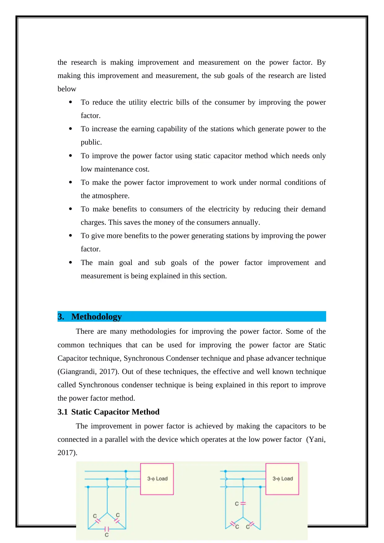
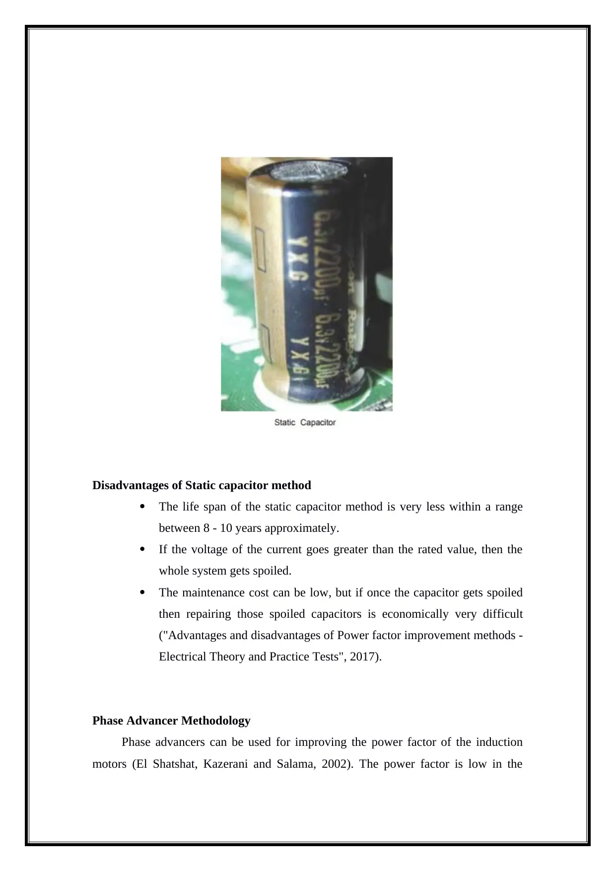
3.1 Static Capacitor Method
The improvement in power factor is achieved by making the capacitors to be
connected in a parallel with the device which operates at the low power factor (Yani,
2017).
making this improvement and measurement, the sub goals of the research are listed
below
To reduce the utility electric bills of the consumer by improving the power
factor.
To increase the earning capability of the stations which generate power to the
public.
To improve the power factor using static capacitor method which needs only
low maintenance cost.
To make the power factor improvement to work under normal conditions of
the atmosphere.
To make benefits to consumers of the electricity by reducing their demand
charges. This saves the money of the consumers annually.
To give more benefits to the power generating stations by improving the power
factor.
The main goal and sub goals of the power factor improvement and
measurement is being explained in this section.
3. Methodology
There are many methodologies for improving the power factor. Some of the
common techniques that can be used for improving the power factor are Static
Capacitor technique, Synchronous Condenser technique and phase advancer technique
(Giangrandi, 2017). Out of these techniques, the effective and well known technique
called Synchronous condenser technique is being explained in this report to improve
the power factor method.
3.1 Static Capacitor Method
The improvement in power factor is achieved by making the capacitors to be
connected in a parallel with the device which operates at the low power factor (Yani,
2017).
⊘ This is a preview!⊘
Do you want full access?
Subscribe today to unlock all pages.
Trusted by 1+ million students worldwide
Disadvantages of Static capacitor method
The life span of the static capacitor method is very less within a range
between 8 - 10 years approximately.
If the voltage of the current goes greater than the rated value, then the
whole system gets spoiled.
The maintenance cost can be low, but if once the capacitor gets spoiled
then repairing those spoiled capacitors is economically very difficult
("Advantages and disadvantages of Power factor improvement methods -
Electrical Theory and Practice Tests", 2017).
Phase Advancer Methodology
Phase advancers can be used for improving the power factor of the induction
motors (El Shatshat, Kazerani and Salama, 2002). The power factor is low in the
Paraphrase This Document
Need a fresh take? Get an instant paraphrase of this document with our AI Paraphraser
induction motors because the stator winding which draws the exciting current and this
is lower than the supplied voltage of about 90 degree (Alrikabi, 2017).
Disadvantages of the Phase Advancer
The phase advancers are not feasible to use as they are not compatible
economically.
The phase advancers cannot be used for other motors than the induction
motors.
Comparing the disadvantages of the above two techniques, synchronous
condenser is found to be an effective technique for improving the power factor.
The working of synchronous condenser is explained below in detail (Alrikabi,
2017).
3.2 Synchronous Condenser Method
When the synchronous motor takes a leading current during the over excited
condition. This acts as a capacitor. If the synchronous motor runs without any load
then it is called as the synchronous condenser. When the synchronous condenser is
connected in parallel with the current supply, then it make use of the leading current
which is used for neutralising the component of the load which is a lagging
component. The synchronous condenser makes use of the current which is used to
lead the voltage at a particular angle (Vaez-Zadeh and Hosseini, 2011). The current
that is achieved as the result is defined as the sum of the phase of the current and it
gets lagged over the voltage by a particular angle. It is found that the normal current is
less than the lagging current and so the power factor is higher than the lagging power
factor (Khaing, 2014).
This synchronous condenser can be used to improve the power factor of any
system by varying the level of excitation (Brunetti, Oberto and Sellone, 2009). The
magnets that are present in the synchronous condenser will have some strength, that
strength should be increased which helps in increasing the attraction of the magnets.
Loads that are carried out for domestic and industrial uses are maximum inductive
loads. A synchronous condenser or a synchronous motor is connected in parallel with
motors that are used in the industries as a compensator in the electrical power
generating stations (Radio-electronics.com, 2017). When compared with the other
devices like compensator like banks, reactors, capacitor and synchronous condenser
contains some advantages in the variation with power factor ("How do synchronous
motors help in improving the power factor?", 2017).
Synchronous motor is also known as three phase motor which consists of 2
types of winding called 3 phase winding of armature and a winding of DC field
(Powermatrix.in, 2017). There is another winding known as Starting winding which is
named as winding of amortisseur ("Synchronous condenser for Power factor
improvement", 2017).
Advantages of Synchronous Condenser
High Reliability
Power factor is adjusted in a step less way.
There is no generation of harmonics.
This method will not get affected using harmonics.
Synchronous condenser is expected nearly 25 years of the life span.
The maintenance cost required is low, the part called periodic bearing
greasing is important for this technique ("Synchronous condenser for Power
factor improvement", 2017).
Principles of the operation
Current Transformer and the potential transformer steps down the values of the
voltage and the supplied current (Circuit Globe, 2017).
The output signal that is generated using the current transformer (CT) and the
potential transformer (PT) are given as the input value for the ZCD.
ZCD is the device which is used for converting the voltage and the current that
is sinusodial nature into CT and PT into the square wave.
The square waves that corresponds to the voltage and current are taken and
given as an input to the XOR gate.
If there occurs any difference in the phase between the two sqaure wave inputs
of the XOR gate, then the output signals of the XOR gate becomes high for a certain
amount of time that is equal to the phase difference between the voltage and the
current.
The output signal that is achieved from the XOR gate is taken and it is
provided as an input signal to the microcontroller.
Microcontroller is used for calculating the difference of phase between the
voltage and current and it is also used for calculating the power factor.
⊘ This is a preview!⊘
Do you want full access?
Subscribe today to unlock all pages.
Trusted by 1+ million students worldwide
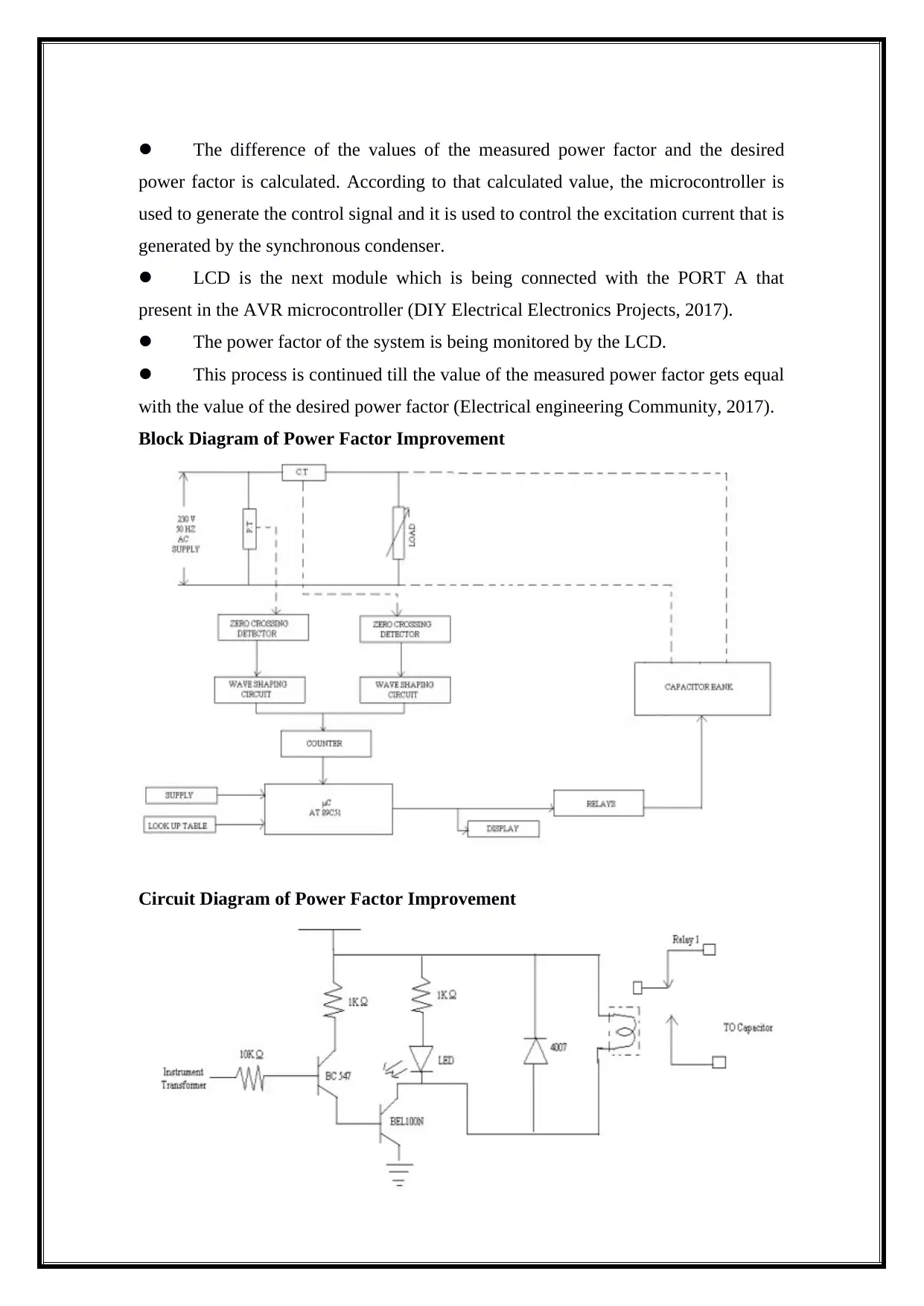
The difference of the values of the measured power factor and the desired
power factor is calculated. According to that calculated value, the microcontroller is
used to generate the control signal and it is used to control the excitation current that is
generated by the synchronous condenser.
LCD is the next module which is being connected with the PORT A that
present in the AVR microcontroller (DIY Electrical Electronics Projects, 2017).
The power factor of the system is being monitored by the LCD.
This process is continued till the value of the measured power factor gets equal
with the value of the desired power factor (Electrical engineering Community, 2017).
Block Diagram of Power Factor Improvement
Circuit Diagram of Power Factor Improvement
Paraphrase This Document
Need a fresh take? Get an instant paraphrase of this document with our AI Paraphraser
4. Experimental Setup
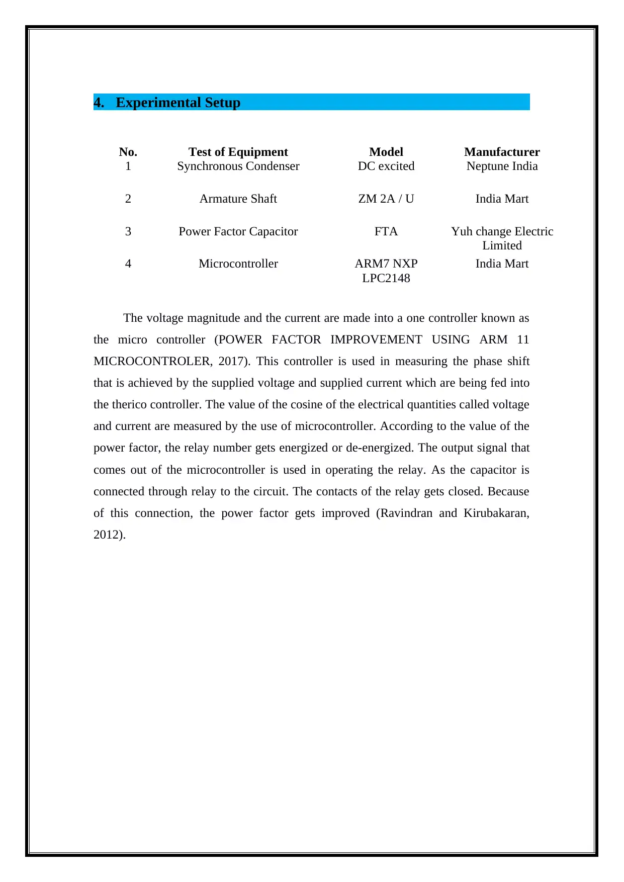
The voltage magnitude and the current are made into a one controller known as
the micro controller (POWER FACTOR IMPROVEMENT USING ARM 11
MICROCONTROLER, 2017). This controller is used in measuring the phase shift
that is achieved by the supplied voltage and supplied current which are being fed into
the therico controller. The value of the cosine of the electrical quantities called voltage
and current are measured by the use of microcontroller. According to the value of the
power factor, the relay number gets energized or de-energized. The output signal that
comes out of the microcontroller is used in operating the relay. As the capacitor is
connected through relay to the circuit. The contacts of the relay gets closed. Because
of this connection, the power factor gets improved (Ravindran and Kirubakaran,
2012).
No. Test of Equipment Model Manufacturer
1 Synchronous Condenser DC excited Neptune India
2 Armature Shaft ZM 2A / U India Mart
3 Power Factor Capacitor FTA Yuh change Electric
Limited
4 Microcontroller ARM7 NXP
LPC2148
India Mart
5. Results and Calculation
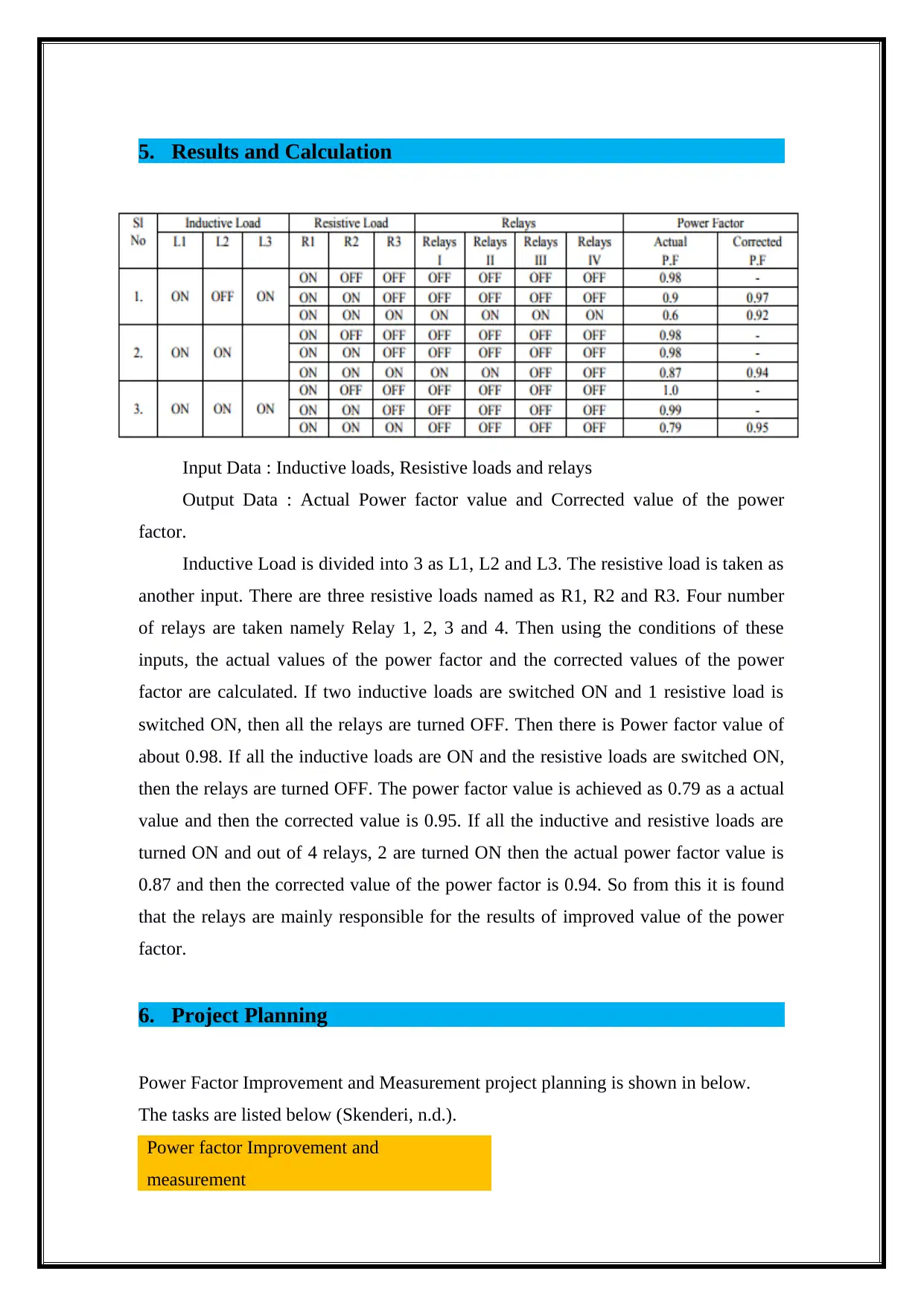
Input Data : Inductive loads, Resistive loads and relays
Output Data : Actual Power factor value and Corrected value of the power
factor.
Inductive Load is divided into 3 as L1, L2 and L3. The resistive load is taken as
another input. There are three resistive loads named as R1, R2 and R3. Four number
of relays are taken namely Relay 1, 2, 3 and 4. Then using the conditions of these
inputs, the actual values of the power factor and the corrected values of the power
factor are calculated. If two inductive loads are switched ON and 1 resistive load is
switched ON, then all the relays are turned OFF. Then there is Power factor value of
about 0.98. If all the inductive loads are ON and the resistive loads are switched ON,
then the relays are turned OFF. The power factor value is achieved as 0.79 as a actual
value and then the corrected value is 0.95. If all the inductive and resistive loads are
turned ON and out of 4 relays, 2 are turned ON then the actual power factor value is
0.87 and then the corrected value of the power factor is 0.94. So from this it is found
that the relays are mainly responsible for the results of improved value of the power
factor.
6. Project Planning
Power Factor Improvement and Measurement project planning is shown in below.
The tasks are listed below (Skenderi, n.d.).
Power factor Improvement and
measurement
⊘ This is a preview!⊘
Do you want full access?
Subscribe today to unlock all pages.
Trusted by 1+ million students worldwide
1 out of 21
Related Documents


Your All-in-One AI-Powered Toolkit for Academic Success.
+13062052269
info@desklib.com
Available 24*7 on WhatsApp / Email
![[object Object]](/_next/static/media/star-bottom.7253800d.svg)
Unlock your academic potential
Copyright © 2020–2026 A2Z Services. All Rights Reserved. Developed and managed by ZUCOL.