Modeling in System Analysis and Design: IMAT5205 Assignment Report
VerifiedAdded on 2022/09/07
|13
|2123
|15
Report
AI Summary
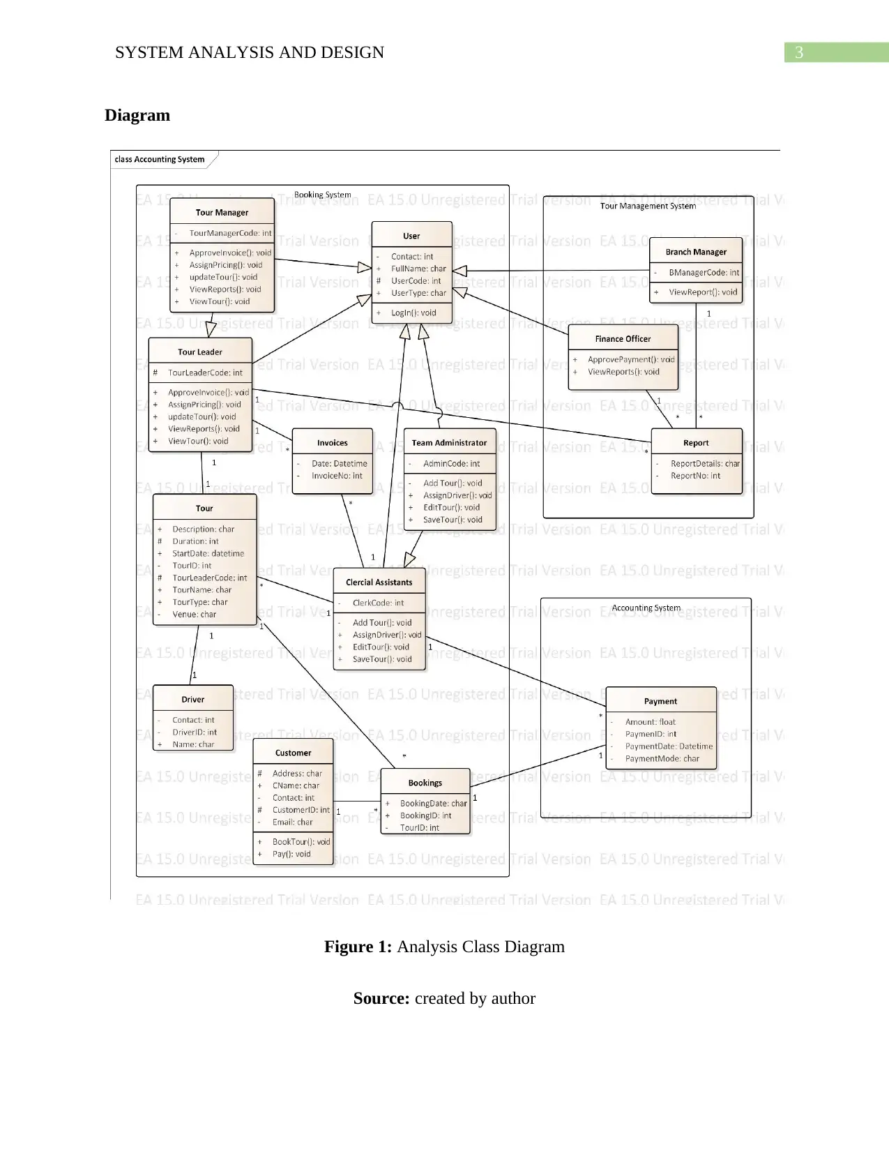
This report presents a comprehensive analysis of system analysis and design, focusing on the application of UML (Unified Modeling Language) diagrams and CASE (Computer-Aided Software Engineering) tools in the context of a tour management system. The report is structured into three parts, beginning with an analysis using class and communication diagrams to represent the static and interactive aspects of the system, respectively. The class diagram illustrates the system's structure, including classes, attributes, and relationships, while the communication diagram details the interactions between objects. The second part of the report utilizes a sequence diagram to depict the temporal sequence of interactions involved in recording a new tour. The final part evaluates the use of CASE tools, specifically Enterprise Architect, in the development process, highlighting their benefits in terms of automation, error reduction, and accelerated development. The report concludes with a discussion of the advantages of using UML and CASE tools together, emphasizing their role in streamlining software development and generating code from visual models. The report also includes references to relevant literature.

Running head: SYSTEM ANALYSIS AND DESIGN
SYSTEM ANALYSIS AND DESIGN
Name of the Student
Name of the University
Author Note
SYSTEM ANALYSIS AND DESIGN
Name of the Student
Name of the University
Author Note
Secure Best Marks with AI Grader
Need help grading? Try our AI Grader for instant feedback on your assignments.

1SYSTEM ANALYSIS AND DESIGN
Table of Contents
Part 1................................................................................................................................................2
Analysis Class Diagram...............................................................................................................2
Description...............................................................................................................................2
Diagram...................................................................................................................................3
Summary..................................................................................................................................4
Communication Diagram.............................................................................................................4
Description...............................................................................................................................4
Diagram...................................................................................................................................5
Summary..................................................................................................................................5
Part 2................................................................................................................................................6
Sequence Diagram.......................................................................................................................6
Description...............................................................................................................................6
Diagram...................................................................................................................................6
Summary..................................................................................................................................8
Part 3................................................................................................................................................8
Evaluation....................................................................................................................................8
References........................................................................................................................................9

2SYSTEM ANALYSIS AND DESIGN
Part 1
Analysis Class Diagram
Description
Class Diagram comes under the Unified modelling language in Object oriented analysis.
It represents the static view along with the system structure using classes and methods. The class
includes the attributes referred from the real world objects. It shows the both structural and
behavioural features of the system (Lu, Mao and Li 2016). It is the only diagram that can be
transformed directly to the object oriented languages which is the reason why it is widely used. It
describes the functions of the system and helps in identifying the components and architecture of
the software. It is also used in reverse and forward engineering in software development Life
cycle.

3SYSTEM ANALYSIS AND DESIGN
Diagram
Figure 1: Analysis Class Diagram
Source: created by author
Diagram
Figure 1: Analysis Class Diagram
Source: created by author
Secure Best Marks with AI Grader
Need help grading? Try our AI Grader for instant feedback on your assignments.

4SYSTEM ANALYSIS AND DESIGN
Summary
In this current scenario of the creating new records for tour, a class diagram is developed
using the information available in the case study and few assumptions. Different roles are
responsible for viewing the tour differently and work within the system. Hence the generalization
between the user class and different roles are used for keeping the common methods and
attributes in a single class (Zaborowski 2016). As Clerical assistant is responsible for adding and
editing tour details hence the Clerical Assistant class and the tour class is directly associated. On
another hand, tour leader of the each tour can view, update and make the pricing of the tour. The
tour Leader class and Tour class is also associated. The customer class is related to the booking
class which is related to the tour and the payment details. Here, the payment related
functionalities comes under the accounting system, branch manager, finance officer and tour
report comes under the Tour management system and the rest of the classes are related to the
booking system.
Communication Diagram
Description
Communication diagram in UML, is a one kind of interaction diagram which explains the
interaction between the objects. In other words, it can be referred as the enhanced structure of
the object diagram. The interaction is showed with the help of objects, boundaries, control,
entities and the messages between them. The direction of the message represents the sending
point and the receiving point of the message (Belghiat, Chaoui and Beldjehem 2015). It can be
converted from the system sequence diagram without using the fragments and structuring
mechanism. It is also known as collaboration diagram. The use of messages help in delivering
the functionalities of use cases and operations.

5SYSTEM ANALYSIS AND DESIGN
Diagram
Figure 2: Communication Diagram
Source: created by author
Summary
In this scenario the use case ‘Record New Tour’ is realized and the communication
between the objects, controls, boundaries and entities are shown. It shows how the user can view
the tour lists. The users are the staffs who have their different roles including, tour manager,
branch manager, finance officer, tour leader, clerical assistant etc. It also shows the Clerical
assistant is responsible for the adding tours and how the messages is transmitted over the
interaction. The messages are used for calling the functions which will execute the adding and

6SYSTEM ANALYSIS AND DESIGN
saving the tour in the tour entity and displaying in the tour list within the system (Swain et al.
2014). The tour list can be shown by fetching the data in the system. At last the Driver object is
used and its entity for assigning a single or multiple drivers for a tour. This work is also done by
the clerical assistant.
Part 2
Sequence Diagram
Description
The sequence diagram in UML modelling represents the communication between the
objects and user over a time period arranged in sequence. It uses the objects and classes to depict
the involvement of the sequence of the messages between them to perform the system task. It is
mainly related to the use case realization in a UML (Han et al. 2016). It is drawn with the help of
parallel vertical lines, processes and objects with their messages using arrows simultaneously.
The order of the messages show in a sequence diagram allows the representation of simple
runtime in graphical manner. By using the messages, objects calls the method for particular
function to happen.
Diagram
Paraphrase This Document
Need a fresh take? Get an instant paraphrase of this document with our AI Paraphraser

7SYSTEM ANALYSIS AND DESIGN

8SYSTEM ANALYSIS AND DESIGN
Figure 3: Sequence Diagram
Source: created by author
Summary
The realization of the use case ‘Record New Tour’ and its behavioural interaction is done
here with the help of sequence diagram. For adding a new tour, the objects required are the
clerical assistant, system and the database from the backend. It represents the flow of messages
between these three objects in a chronological manner. Every time a change is made by the
clerical assistant initiates the save method from the system to the database which instantly saves
the added data. The data retrieval is also done from the database where the clerical assistant
identifies the tour list by the tour leader Codes. In parallel of this, if the clerical assistant inputs
the invalid tour leader code then the system will throw an error. Otherwise the data can be added
for the tour details by choosing the tour leader code. An alternative fragment is used for this
optional path (Misbhauddin and Alshayeb 2015). Another alternate fragment is used for adding
the multiple driver where the clerical assistant can select “Yes” or “No” for proceeding the
adding tour function.
Part 3
Evaluation
CASE (Computer Aided Software Engineering) tools is a methodological approach for
developing software which have many modelling and development tools in one application. It
helps in meeting the system goals, objectives and achieving a high quality software (Pirolli
2014). It is used to automate some activity of the development in a preventive way. The CASE

9SYSTEM ANALYSIS AND DESIGN
tool is not only limited to the one or few stages of the Software Development Life Cycle. It also
helps in the maintenance of the software with the help of forward and reverse engineering
(Osman and Chaudron 2014). In the Current Scenario of the World-Wide Tour the tour offered a
lot more automated activities in the development of the diagrams. Along with that, it is
preventive in nature, hence there are less chance of basic mistakes which can be made while
developing manually. The CASE tool is used here is Enterprise Architect which have predefined
parameters of almost all type UML, other developing, analysing and maintaining tools for the
object oriented software. Developing diagram in UML modelling is easier as the implementation
of the classes, attributes, operations, relationship and their types were systematic and follows the
Object oriented architecture (Teruel et al. 2014). Hence, it is not much likely to make any
mistakes in the modelling. Also, the realization of attributes and operations of one class to
another is automated so there is no chance for skipping any small thing. It has provided the
simplicity by providing the tools for the design and implementation both. It has helped in
successfully accelerate the development period.
The tools for the diagram helps in representing the components, objects and the flow
among the various systems in a graphical manner. The process modelling tool and the model
wizard helps in creating the software’s process which helps in the coding phase of the software.
Apart from the process and structure modelling a CASE tool also consists of project management
and documenting tools (Guney 2015). The whole package of the CASE tool is more reliable in
the development of several other methods of software development such as web development,
prototyping etc. The main benefits of using a CASE tool are to save resources, accelerate, reduce
errors, identify bugs and increase the productivity in software the development.
Secure Best Marks with AI Grader
Need help grading? Try our AI Grader for instant feedback on your assignments.

10SYSTEM ANALYSIS AND DESIGN
On other hand, UML (Unified Modelling Language) is the object based modelling
language generally used in the software development (Dennis, Wixom and Tegarden 2015). It
helps in providing an overview of the system’s functions and process to the programmer or
developer of the software. The CASE tool used here not only develops the UML diagram, it also
generates the language code from the developed UML which is the main benefit of using UML
and Enterprise Architect together. It means any object oriented language can be generated from
the developed class diagram for the World-Wide Tour. Which will also consider the
communication diagram and sequence diagram to determine the flow of the process using
messages and the class diagram will generate the methods and the variables for the attribute
(Lopata et al. 2014). With all these understandings of CASE tool, UML and Object oriented
language, it becomes easier and more efficient to develop any software for the developer.

11SYSTEM ANALYSIS AND DESIGN
References
Belghiat, A., Chaoui, A. and Beldjehem, M., 2015, August. Capturing and verifying dynamic
program behaviour using UML communication diagrams and pi-calculus. In 2015 IEEE
International Conference on Information Reuse and Integration (pp. 318-325). IEEE.
Dennis, A., Wixom, B.H. and Tegarden, D., 2015. Systems analysis and design: An object-
oriented approach with UML. John wiley & sons.
Guney, D., 2015. The importance of computer-aided courses in architectural
education. Procedia-Social and Behavioral Sciences, 176, pp.757-765.
Han, D., Xing, J., Yang, Q., Wang, H. and Zhang, X., 2016, June. Formal Sequence: Extending
UML Sequence Diagram for Behavior Description and Formal Verification. In 2016 IEEE 40th
Annual Computer Software and Applications Conference (COMPSAC) (Vol. 2, pp. 474-481).
IEEE.
Lopata, A., Veitaite, I., Gudas, S. and Butleris, R., 2014. CASE tool component—knowledge-
based subsystem. UML Diagrams Generation Process. Transformations in Business &
Economics, 13(2B), pp.676-696.
Lu, Y., Mao, X. and Li, Z., 2016. Assessing software maintainability based on class diagram
design: A preliminary case study. Lecture Notes on Software Engineering, 4(1), p.53.
Misbhauddin, M. and Alshayeb, M., 2015. Extending the UML use case metamodel with
behavioral information to facilitate model analysis and interchange. Software & Systems
Modeling, 14(2), pp.813-838.

12SYSTEM ANALYSIS AND DESIGN
Osman, H. and Chaudron, M.R., 2014. Correctness and Completeness of CASE Tools in Reverse
EngineeringSource Code into UML Model. GSTF Journal on Computing (JoC), 2(1).
Pirolli, P., 2014, January. Computer-aided instructional design systems. In Intelligent Tutoring
Systems (pp. 119-140). Psychology Press.
Swain, R.K., Panthi, V., Mohapatra, D.P. and Behera, P.K., 2014. Prioritizing test scenarios from
UML communication and activity diagrams. Innovations in Systems and Software
Engineering, 10(3), pp.165-180.
Teruel, M.A., Navarro, E., López-Jaquero, V., Montero, F. and González, P., 2014. A CSCW
requirements engineering CASE tool: development and usability evaluation. Information and
Software Technology, 56(8), pp.922-949.
Zaborowski, M.I.R.O.S.Ł.A.W., 2016. Generalization and composition relationships between
objects of enterprise process control systems. In Proceedings of the 11th Scientific Conference
Internet in the Information Society (pp. 405-418).
1 out of 13
Related Documents

Your All-in-One AI-Powered Toolkit for Academic Success.
+13062052269
info@desklib.com
Available 24*7 on WhatsApp / Email
Unlock your academic potential
© 2024 | Zucol Services PVT LTD | All rights reserved.