System Analysis and Design Report: Diagrams, Analysis and Evaluation
VerifiedAdded on 2020/10/22
|11
|2120
|490
Report
AI Summary
This report delves into the realm of System Analysis and Design (SAD), employing Unified Modeling Language (UML) diagrams to dissect system structures and behaviors. It begins with an exploration of class diagrams, elucidating their role in depicting system structure, attributes, and relationships. The report then moves on to communication diagrams, illustrating interactions between system components and the flow of information. Sequence diagrams are analyzed, detailing the order of events and decision-making processes within the system. The report also discusses the evaluation of the system using CASE tools, their functionalities, and their support for various stages of the Software Development Life Cycle (SDLC). Furthermore, it emphasizes the importance of UML modeling in understanding the static and dynamic aspects of a system. The assignment concludes by highlighting the significance of UML in creating system blueprints and facilitating effective software design and analysis.
System Analysis and
Design
Design
Paraphrase This Document
Need a fresh take? Get an instant paraphrase of this document with our AI Paraphraser
Table of Contents
PART 1............................................................................................................................................1
Class Diagram..................................................................................................................................1
a). Analysis class Diagram and its uses in System Analysis and Design....................................1
b). Analysis Class Diagram for 'Record New Tour.....................................................................1
c). Brief Summary involved in creation of the Class Diagram....................................................2
Communication Diagram.................................................................................................................3
a). Description of Communication diagram and its uses in System Analysis and Design..........3
b). Communication Diagram.......................................................................................................3
c). Brief Summary to describe the decisions made during creation of communication Diagram
......................................................................................................................................................4
PART 2............................................................................................................................................4
Sequence..........................................................................................................................................4
a). Description of Sequence Diagram and its uses in System Analysis and Design....................4
b). UML Sequence diagram of 'Record New Tour'.....................................................................5
c).Brief summary to justify the Decision making while Making the UML sequence Diagram.. 5
PART 3............................................................................................................................................5
Evaluation........................................................................................................................................5
REFERENCES................................................................................................................................8
PART 1
Class Diagram
a). Analysis class Diagram and its uses in System Analysis and Design.
In Software engineering, Unified Modelling Language contains consists of Class diagram
which mainly helps in describing the structure of the system in the form of Class. The Class
Diagram Diagram describes their attributes, operations and relationship among among different
objects in the form of structured diagram. It helps in determining the static view of System which
develops the sense of evaluating and associating the complexities of System Analysis and Design
(Chaudron, 2017). It not only used to visualise the Static View but also used to construct the
executable code to forward and reverse the engineering of any system. Some uses of the class
Diagram in SAD are described below:
This is used to construct Software Application with the helps of class and objects.
This is used to show the collaboration among elements of Static View.
It basically used to Describe the functionalities in a system in an structured way.
b). Analysis Class Diagram for 'Record New Tour.
1
⊘ This is a preview!⊘
Do you want full access?
Subscribe today to unlock all pages.
Trusted by 1+ million students worldwide
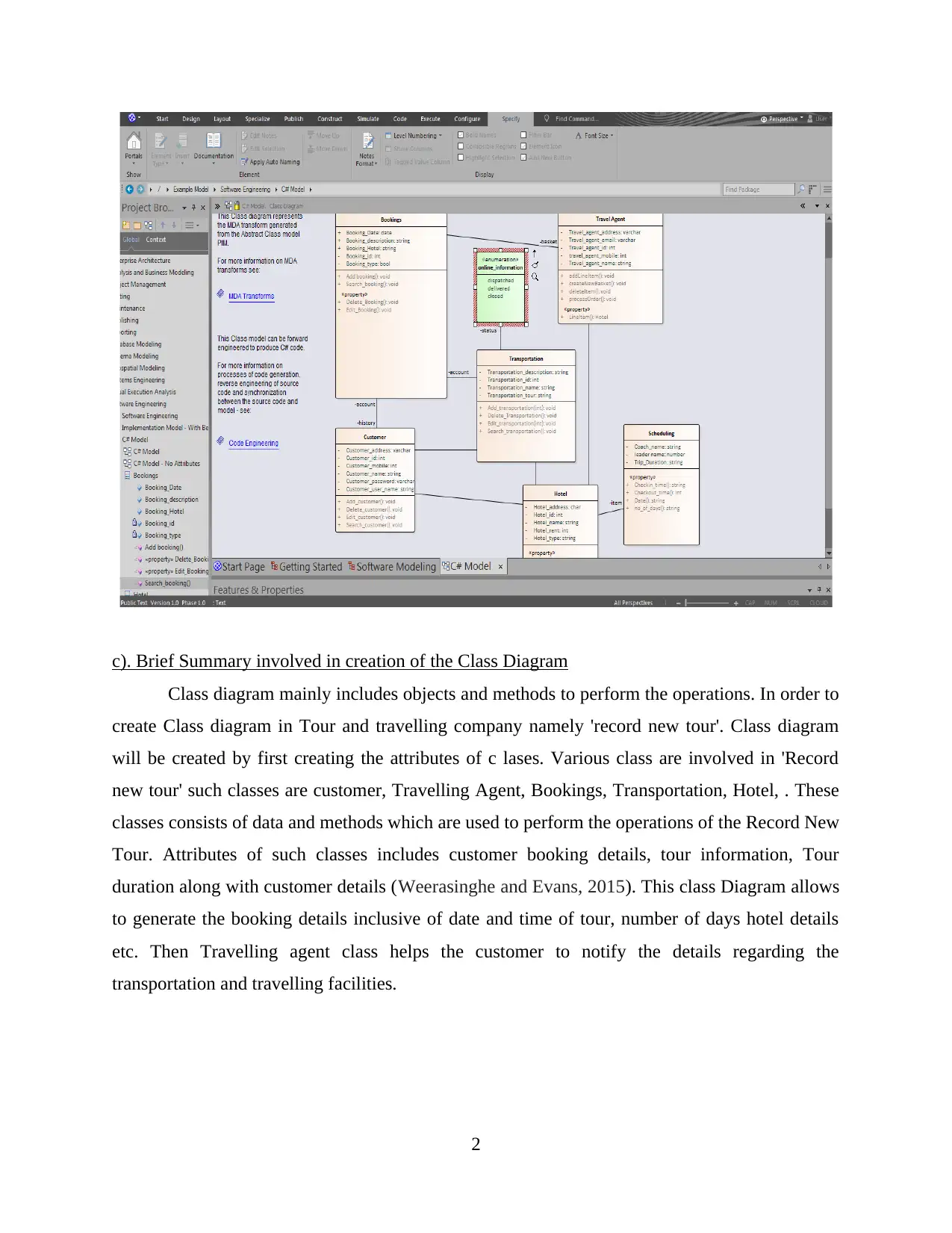
c). Brief Summary involved in creation of the Class Diagram
Class diagram mainly includes objects and methods to perform the operations. In order to
create Class diagram in Tour and travelling company namely 'record new tour'. Class diagram
will be created by first creating the attributes of c lases. Various class are involved in 'Record
new tour' such classes are customer, Travelling Agent, Bookings, Transportation, Hotel, . These
classes consists of data and methods which are used to perform the operations of the Record New
Tour. Attributes of such classes includes customer booking details, tour information, Tour
duration along with customer details (Weerasinghe and Evans, 2015). This class Diagram allows
to generate the booking details inclusive of date and time of tour, number of days hotel details
etc. Then Travelling agent class helps the customer to notify the details regarding the
transportation and travelling facilities.
2
Paraphrase This Document
Need a fresh take? Get an instant paraphrase of this document with our AI Paraphraser
Communication Diagram
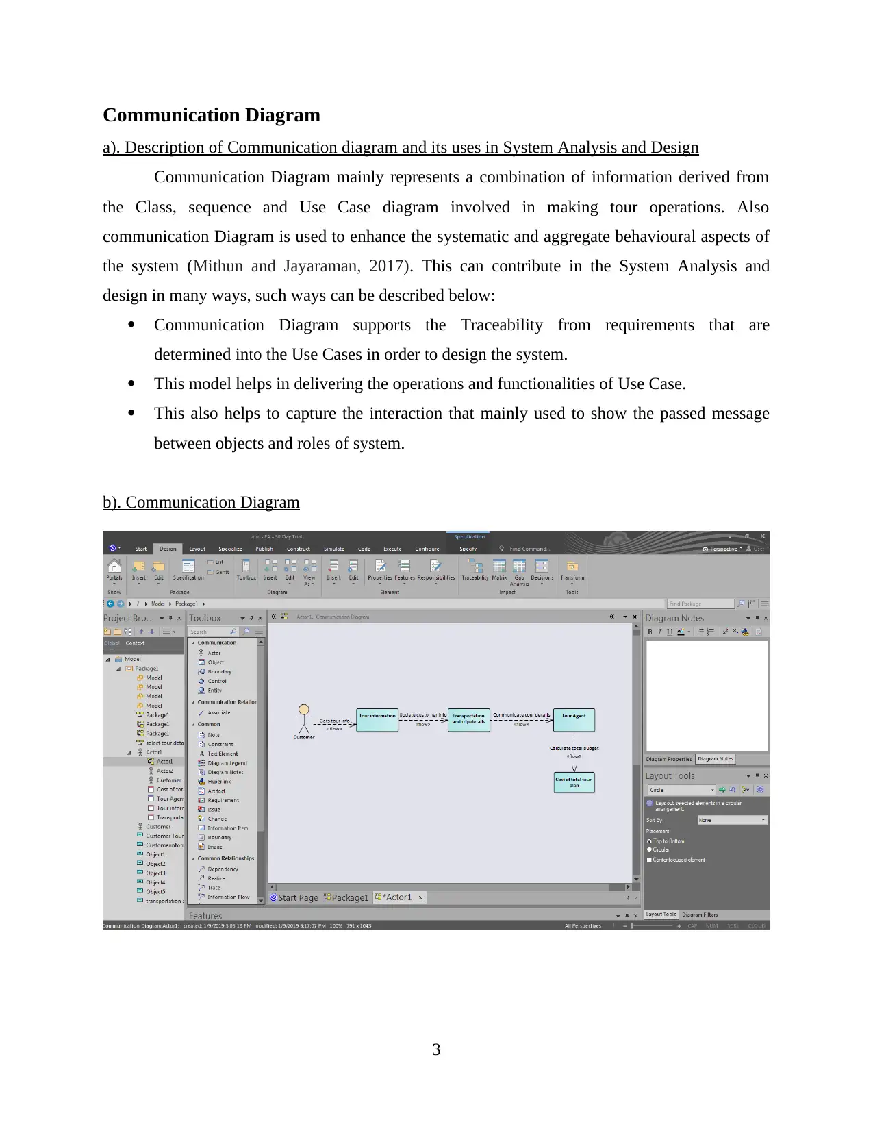
a). Description of Communication diagram and its uses in System Analysis and Design
Communication Diagram mainly represents a combination of information derived from
the Class, sequence and Use Case diagram involved in making tour operations. Also
communication Diagram is used to enhance the systematic and aggregate behavioural aspects of
the system (Mithun and Jayaraman, 2017). This can contribute in the System Analysis and
design in many ways, such ways can be described below:
Communication Diagram supports the Traceability from requirements that are
determined into the Use Cases in order to design the system.
This model helps in delivering the operations and functionalities of Use Case.
This also helps to capture the interaction that mainly used to show the passed message
between objects and roles of system.
b). Communication Diagram
3
c). Brief Summary to describe the decisions made during creation of communication Diagram
Communication Diagram can also be referred as a collaboration Diagram and this helps
in establishing a communication link between all the actors and objects. In this process of
creating a communication Diagram, one has to take help from the Unified modelling languages
in order to create communication link. In this Communication Diagram, developer has to make
the decisions regarding the objects and actors involved in this UML (Ben Abdessalem Karaa,
and et.al., 2016). This is mainly helps the managers in designing an effective system and
Communication Diagram allows the managers to identify the communication link between main
actor and object in order to flow the systematic information. However, no decisions could be
taken in the absence of information and communication is the one that flows through official
channels in the form of actor and object. In 'Record New Tour' actor is customers while
Travelling agents and customer info are the objects.
PART 2
Sequence
a). Description of Sequence Diagram and its uses in System Analysis and Design
This helps in modelling of the flow of logics which are applied in a system in order to
validate the logics. This can be commonly used for Analysis and design purpose. It can be used
for the following purpose in Analysis and design, such uses are as follows:
It is generally used to describe proper order of the system.
It also helps in understanding the system requirements in order to document existing
system or create a new system.
This Diagram basically shows the details of events which is generated by actors in order
to analyse the system from outside.
4
⊘ This is a preview!⊘
Do you want full access?
Subscribe today to unlock all pages.
Trusted by 1+ million students worldwide
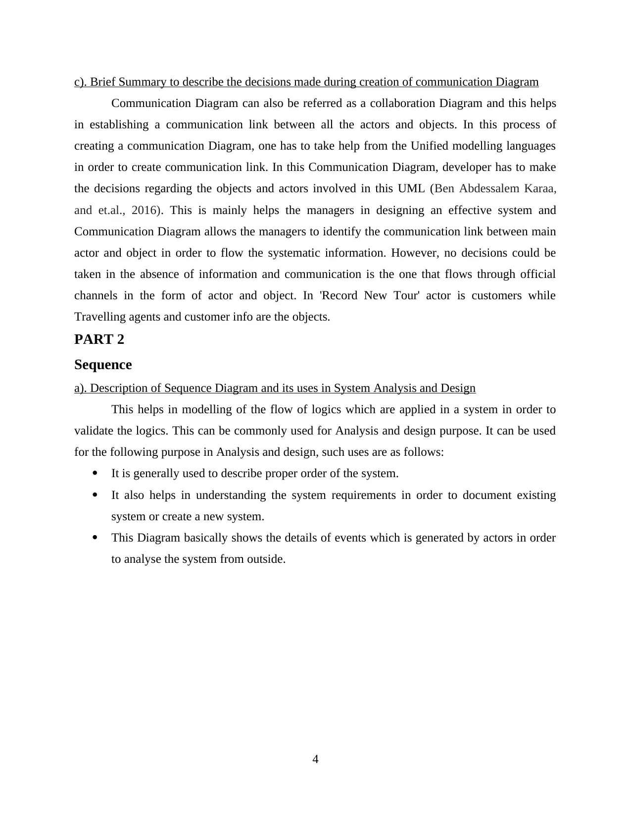
b). UML Sequence diagram of 'Record New Tour'
c).Brief summary to justify the Decision making while Making the UML sequence Diagram.
The UML sequence involved in making the decisions regarding activities and actor
involved in sequential process. This sequence diagram helps in taking the decisions regarding the
information flow in a sequence manner. This sequence diagram helps the managers in taking the
decisions of the booking details and customers who are applying for the specific tour. UML
sequence diagram basically helps in taking the decisions for activities that are being done in
System analysis and design.
5
Paraphrase This Document
Need a fresh take? Get an instant paraphrase of this document with our AI Paraphraser
PART 3
Evaluation
Enterprise Architecture is a designing and visual modelling CASE tool. This tool is used
for construction and designing of software systems, modelling industry based domains,
modelling business processes. It is mostly used by many organizations and businesses, not only
modelling the architecture of their systems but it is also used for implementation of process
models across full application development life cycle. It can be used by organizations to create
UML diagrams, SDLC life cycle models, business process models etc.
Computer aided software engineering (CASE) is software tool that is used for designing
and implementing applications (Miyamoto, 2017). CASE tools are partially inspired by CAD
tools that are used to design hardware products. CASE tool in wide world tour scenario can be
used to design and analyse management software of world wide tour. It can be used to create and
design different UML diagrams like class diagram, communication diagram, sequence diagram
etc. to understand and visualize the design of the system. CASE tool will help to understand and
visualize the design of the software in terms of structure, behaviour and interaction between
functions and operations. It is simply an automation of methodologies for system and software
development. CASE tools can be used at different stages of software development life cycle
( Chaudron, 2017 ). There are many different types of CASE tools that can be used for covering
SDLC life cycle stages which share common information. CASE tool offers various features that
can be used by organizations like check for syntactic correctness, layering, data dictionary
support, check for consistency and completeness, navigation to linked diagrams, requirements
traceability, automatic report generation, performance analysis, systematic simulation.
Role of analyst and designer can be supported by CASE tools as it will give them a
clarity of the object oriented approach they will follow, will help them in rapid application
development, prototyping, joint application development, life cycle of the software and many
more. There are many CASE tools available that can be used by an analyst or designer like
reverse engineering tool, requirement analysis tool, document production tool, structure analysis
tool, test case generation tool, Code generation tool and software design tool. As it has been
already discussed that these tools are used at different stages of SDLC like requirement analysis
tool can be used at requirement stage of SDLC, test case generation tool can be used at testing
stage etc. All these tools can be used by analyst and designer for creation, designing and analysis
6
of the software at different stages of SDLC life cycle. These tools can also be used in building a
prototype of the system while using SDLC prototype model.
UML (Unified modelling language) is a standard language for specifying, constructing,
visualizing and documenting software system artifices. UML diagrams represent two views of
systems or software i.e. dynamic view ( behavioural) and static view (structural). Dynamic view
is used to emphasis dynamic behaviour of the system by showing collaboration and changes in
internal stages of the objects. It mostly includes activity diagram, sequence diagram, state
machine diagram. Static view is used to emphasis static structure of the software or the system
using attributes, objects, relationships and operations. It mostly includes composite structure
diagrams and class diagram.
There are different types of UML modelling that uses different diagrams to represent
structure, behaviour and architecture of the system. UML modelling can help analyst and
designer to understand the static features of the software and the system, understand the
interaction in the software and the system and to represent and understand the overall framework
of the system. It can also be said that UML modelling helps then to understand the overall
blueprint of the system, check whether all the components are in their place or not and
interaction between the users, activity and objects ( Weerasinghe and Evans, 2015 ). All these
different types of modelling consist of different diagrams which helps analyst and designers to
understand the system like structural modelling consist of object, class, deployment, component,
package and composite structure diagrams. Behavioural modelling consist of interaction, activity
and use case diagram. At last architectural modelling consist of both the type of modelling
elements of the system. It consists of package diagram.
Finally it can be said that it is pictorial language that is used to make blueprints of
software or system. It is normally used to model software systems and is not limited within the
boundaries. It is also used to model non software systems like manufacturing unit process flow.
7
⊘ This is a preview!⊘
Do you want full access?
Subscribe today to unlock all pages.
Trusted by 1+ million students worldwide
REFERENCES
Books and Journals
Chaudron, M.R., 2017, May. Empirical studies into UML in practice: pitfalls and prospects.
In Modelling in Software Engineering (MiSE), 2017 IEEE/ACM 9th International
Workshop on (pp. 3-4). IEEE.
Weerasinghe, A. and Evans, B., 2015, June. UML-IT: An ITS to Teach Multiple Modelling
Tasks. In International Conference on Artificial Intelligence in Education (pp. 816-
819). Springer, Cham.
Ben Abdessalem Karaa, W., and et.al., 2016. Automatic builder of class diagram (ABCD): an
application of UML generation from functional requirements. Software: Practice and
Experience. 46(11). pp.1443-1458.
Miyamoto, T., 2017. Synthesizing Pareto efficient intelligible state machines from
communication diagram. IEICE TRANSACTIONS on Information and Systems. 100(6).
pp.1200-1209.
Mithun, M. and Jayaraman, S., 2017, September. Comparison of sequence diagram from
execution against design-time state specification. In Advances in Computing,
Communications and Informatics (ICACCI), 2017 International Conference on (pp.
1387-1392). IEEE.
8
Paraphrase This Document
Need a fresh take? Get an instant paraphrase of this document with our AI Paraphraser

9
1 out of 11
Related Documents


Your All-in-One AI-Powered Toolkit for Academic Success.
+13062052269
info@desklib.com
Available 24*7 on WhatsApp / Email
![[object Object]](/_next/static/media/star-bottom.7253800d.svg)
Unlock your academic potential
Copyright © 2020–2026 A2Z Services. All Rights Reserved. Developed and managed by ZUCOL.