System Analysis and Design: UML Diagrams and Evaluation Report

Verified

Added on  2023/04/21

|9
|1852
|295
Report
AI Summary
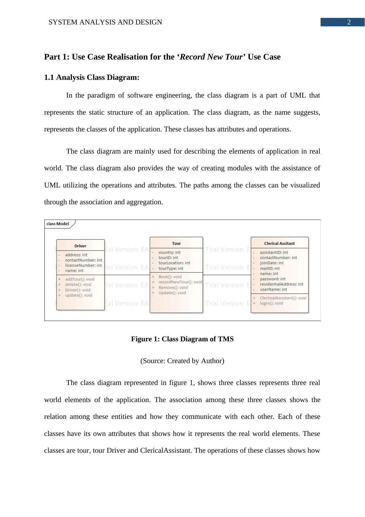
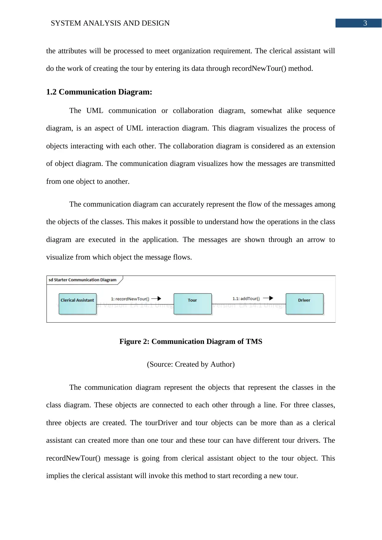
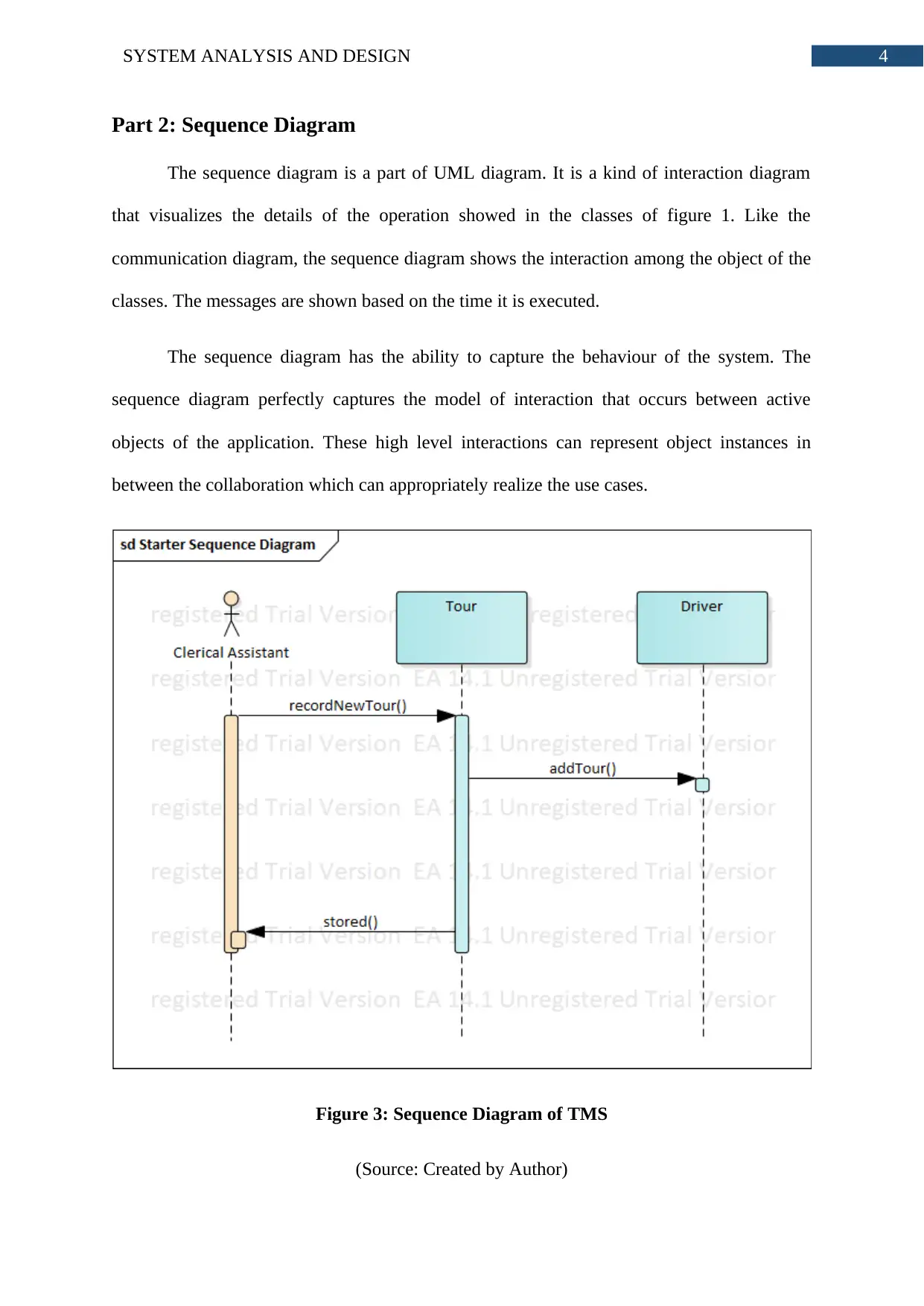
This report presents a comprehensive analysis of system analysis and design, focusing on the application of UML diagrams within the context of the Wide World Tour Management System (TMS). The report begins by detailing the creation and interpretation of an Analysis Class Diagram, illustrating the static structure of the application and the relationships between classes such as Tour, TourDriver, and ClericalAssistant. Following this, a Communication Diagram is presented to visualize the interactions between objects, specifically showcasing the flow of messages during the 'Record New Tour' use case. The report then proceeds to a Sequence Diagram, which elaborates on the temporal order of operations and interactions between objects, including the actor (Clerical Assistant) and the methods involved in recording a new tour. Finally, the report evaluates the use of Computer-Aided Software Engineering (CASE) tools, specifically Enterprise Architect, in the design process, highlighting their role in creating and modifying UML diagrams, and their contribution to understanding the system without needing to focus on coding. The usefulness of the UML models for both structural and behavioral aspects is also discussed.
Document Page
Running head: SYSTEM ANALYSIS AND DESIGN
System Analysis and Design
Name of the Student
Name of the University
Author’s note:
tabler-icon-diamond-filled.svg

Paraphrase This Document

Need a fresh take? Get an instant paraphrase of this document with our AI Paraphraser
Document Page
1SYSTEM ANALYSIS AND DESIGN
Table of Contents
Part 1: Use Case Realisation for the ‘Record New Tour’ Use Case...........................................2
1.1 Analysis Class Diagram:..................................................................................................2
1.2 Communication Diagram:................................................................................................3
Part 2: Sequence Diagram..........................................................................................................4
Part 3: Evaluation.......................................................................................................................5
Bibliography:..............................................................................................................................7
Document Page
2SYSTEM ANALYSIS AND DESIGN
Part 1: Use Case Realisation for the ‘Record New Tour’ Use Case
1.1 Analysis Class Diagram:
In the paradigm of software engineering, the class diagram is a part of UML that
represents the static structure of an application. The class diagram, as the name suggests,
represents the classes of the application. These classes has attributes and operations.
The class diagram are mainly used for describing the elements of application in real
world. The class diagram also provides the way of creating modules with the assistance of
UML utilizing the operations and attributes. The paths among the classes can be visualized
through the association and aggregation.
Figure 1: Class Diagram of TMS
(Source: Created by Author)
The class diagram represented in figure 1, shows three classes represents three real
world elements of the application. The association among these three classes shows the
relation among these entities and how they communicate with each other. Each of these
classes have its own attributes that shows how it represents the real world elements. These
classes are tour, tour Driver and ClericalAssistant. The operations of these classes shows how
Document Page
3SYSTEM ANALYSIS AND DESIGN
the attributes will be processed to meet organization requirement. The clerical assistant will
do the work of creating the tour by entering its data through recordNewTour() method.
1.2 Communication Diagram:
The UML communication or collaboration diagram, somewhat alike sequence
diagram, is an aspect of UML interaction diagram. This diagram visualizes the process of
objects interacting with each other. The collaboration diagram is considered as an extension
of object diagram. The communication diagram visualizes how the messages are transmitted
from one object to another.
The communication diagram can accurately represent the flow of the messages among
the objects of the classes. This makes it possible to understand how the operations in the class
diagram are executed in the application. The messages are shown through an arrow to
visualize from which object the message flows.
Figure 2: Communication Diagram of TMS
(Source: Created by Author)
The communication diagram represent the objects that represent the classes in the
class diagram. These objects are connected to each other through a line. For three classes,
three objects are created. The tourDriver and tour objects can be more than as a clerical
assistant can created more than one tour and these tour can have different tour drivers. The
recordNewTour() message is going from clerical assistant object to the tour object. This
implies the clerical assistant will invoke this method to start recording a new tour.
tabler-icon-diamond-filled.svg

Paraphrase This Document

Need a fresh take? Get an instant paraphrase of this document with our AI Paraphraser
Document Page
4SYSTEM ANALYSIS AND DESIGN
Part 2: Sequence Diagram
The sequence diagram is a part of UML diagram. It is a kind of interaction diagram
that visualizes the details of the operation showed in the classes of figure 1. Like the
communication diagram, the sequence diagram shows the interaction among the object of the
classes. The messages are shown based on the time it is executed.
The sequence diagram has the ability to capture the behaviour of the system. The
sequence diagram perfectly captures the model of interaction that occurs between active
objects of the application. These high level interactions can represent object instances in
between the collaboration which can appropriately realize the use cases.
Figure 3: Sequence Diagram of TMS
(Source: Created by Author)
Document Page
5SYSTEM ANALYSIS AND DESIGN
The sequence diagram has three objects and one of them is an actor. The actor is the
clerical assistant. The clerical assistant starts adding a new tour in the system and the
application initializes the recordNewTour() method. This method calls for the attributes in the
tour class. This tour class then calls the addDriver() method. This method has a parameter
which has driver ID. Based on this ID, the application assigns the driver. After the driver is
assigned, the application replies to the clerical assistant that new tour is stored.
Part 3: Evaluation
The Computer Aided Software Engineering tools or CASE tools are generally used
for supporting the development and maintenance task of software development project. The
CASE tools supports all kind of modelling elements of an application or large system and
various system designs can be done through these CASE tools. The CASE tools are also
capable of automating the SDLC activities. The enterprise architecture, the CASE tool used
in the assignment, has been a greatly important factor in designing three UML diagrams. The
CASE tool has provided all the basic modelling elements that were essential for designing the
diagrams. The Enterprise Architecture has been able to capture both the structural and
behavioural aspects of the Wide World Tour Management System or TMS. The capability of
Enterprise Architecture was not limited to these UML diagrams only, it could allow
designing the database and other parts of the application. The enterprise architect allowed
putting all the elements of the class, communication and sequence diagrams perfectly. The
classes has been done accurately along with showing attributes and operations.
It was easy to modify the UML diagrams after those diagrams were created. The
CASE tool allowed to build the understanding of the system without even considering the
coding aspect. The CASE tool allowed adding new aspects and requirements of the systems
at any stage of the design. The alterations in the name, type of the classes, attributes,
Document Page
6SYSTEM ANALYSIS AND DESIGN
messages or event lifelines were extremely easy. This allowed in putting most of the effort
and concentration on the system analysis and design task not in understanding how the CASE
tool Enterprise Architect is used. The Enterprise Architect provided very easy to use user
interface and user interaction quality. The use case diagram and use case description provided
as a reference for the case study of adding new tour provided an in depth understanding of the
behaviour of the system. This is limited to only adding a new tour operation of the
application. In order to justify the use case to the real case study of Wide World Tour
Management System or TMS, all the aspects of the system needed to be recognized and
analysed. A predefined approach toward the case study of TMS was not appropriate.
Therefore, a tool was need that could increase the possibility of executing the system analysis
part in a customized way. The case tool provided the perfect atmosphere for capturing and
demonstrating the core operations of the system.
The UML models have been utilized for creating both the structural and social
models. Maybe, the greatest preferred standpoint of UML model is that it enables the
designer to model both the structural and conduct model of a framework. This implies
through the UML models just, the designers can dissect and design the inward structure,
messages going through framework components, correspondence, interface necessities,
communication rudiments and the sky is the limit from there. The UML modelling tradition
has such a significant number of models that it can cover every one of the parts of a huge data
framework. The UML is equipped for getting both the static and dynamic parts of a
framework. It is critical to make an UML diagram to catch the fundamental designs of a
framework through which the other complex models can be made.
tabler-icon-diamond-filled.svg

Paraphrase This Document

Need a fresh take? Get an instant paraphrase of this document with our AI Paraphraser
Document Page
7SYSTEM ANALYSIS AND DESIGN
Bibliography:
Abukwaik, H., Naab, M. and Rombach, D., 2015, May. A proactive support for conceptual
interoperability analysis in software systems. In Software Architecture (WICSA), 2015 12th
Working IEEE/IFIP Conference on (pp. 119-122). IEEE.
Alpers, S., Pilipchuk, R., Oberweis, A. and Reussner, R.H., 2018. Identifying Needs for a
Holistic Modelling Approach to Privacy Aspects in Enterprise Software Systems. ICISSP, 18,
pp.74-82.
Gu, F., Zhang, X., Chen, M., Große, D. and Drechsler, R., 2016, March. Quantitative timing
analysis of UML activity diagrams using statistical model checking. In Proceedings of the
2016 Conference on Design, Automation & Test in Europe(pp. 780-785). EDA Consortium.
Leemans, M. and van der Aalst, W.M., 2015, September. Process mining in software
systems: Discovering real-life business transactions and process models from distributed
systems. In 2015 ACM/IEEE 18th International Conference on Model Driven Engineering
Languages and Systems (MODELS) (pp. 44-53). IEEE.\
Nikulchev, E. and Deryugina, O., 2016. Model and Criteria for the Automated Refactoring of
the UML Class Diagrams. International Journal of Advanced Computer Science and
Applications, 7(12), pp.76-79.
Pauker, F., Frühwirth, T., Kittl, B. and Kastner, W., 2016. A systematic approach to OPC UA
information model design. Procedia CIRP, 57, pp.321-326.
Rashid, M., Anwar, M.W., Azam, F. and Kashif, M., 2016. Exploring the platform for
expressing SystemVerilog assertions in model based system engineering. In Information
Science and Applications (ICISA) 2016 (pp. 533-544). Springer, Singapore.
Document Page
8SYSTEM ANALYSIS AND DESIGN
Ruijters, E. and Stoelinga, M., 2015. Fault tree analysis: A survey of the state-of-the-art in
modeling, analysis and tools. Computer science review, 15, pp.29-62.
Singh M, Sharma AK, Saxena R. An UML+ Z framework for validating and verifying the
Static aspect of Safety Critical System. Procedia Computer Science. 2016 Jan 1;85:352-61.
Wichmann, A., Jäger, S., Jungebloud, T., Maschotta, R. and Zimmermann, A., 2016, April.
Specification and execution of system optimization processes with UML activity diagrams.
In Systems Conference (SysCon), 2016 Annual IEEE (pp. 1-7). IEEE.
chevron_up_icon
1 out of 9
circle_padding
hide_on_mobile
zoom_out_icon
[object Object]