System Analysis and Design Project: Body Sculptures Application System

Verified

Added on  2022/10/17

|14
|2238
|405
Project
AI Summary
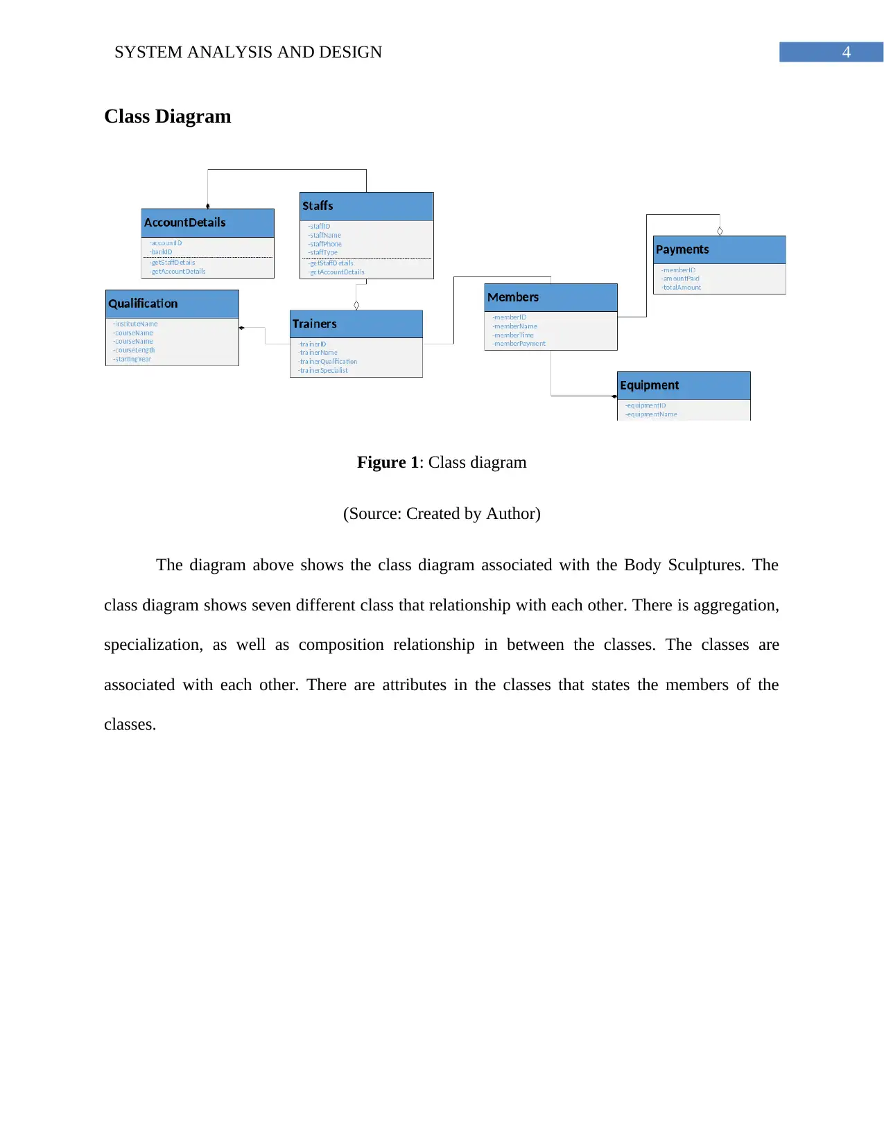
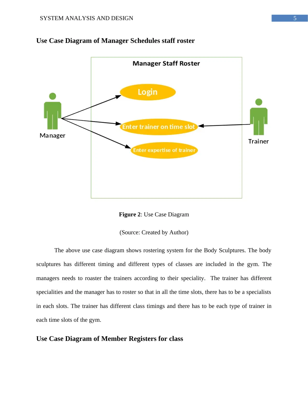
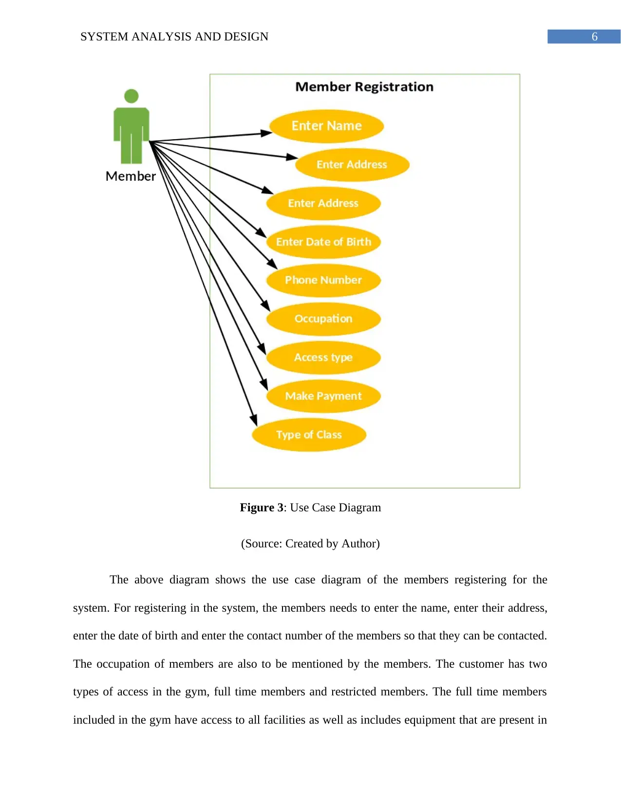
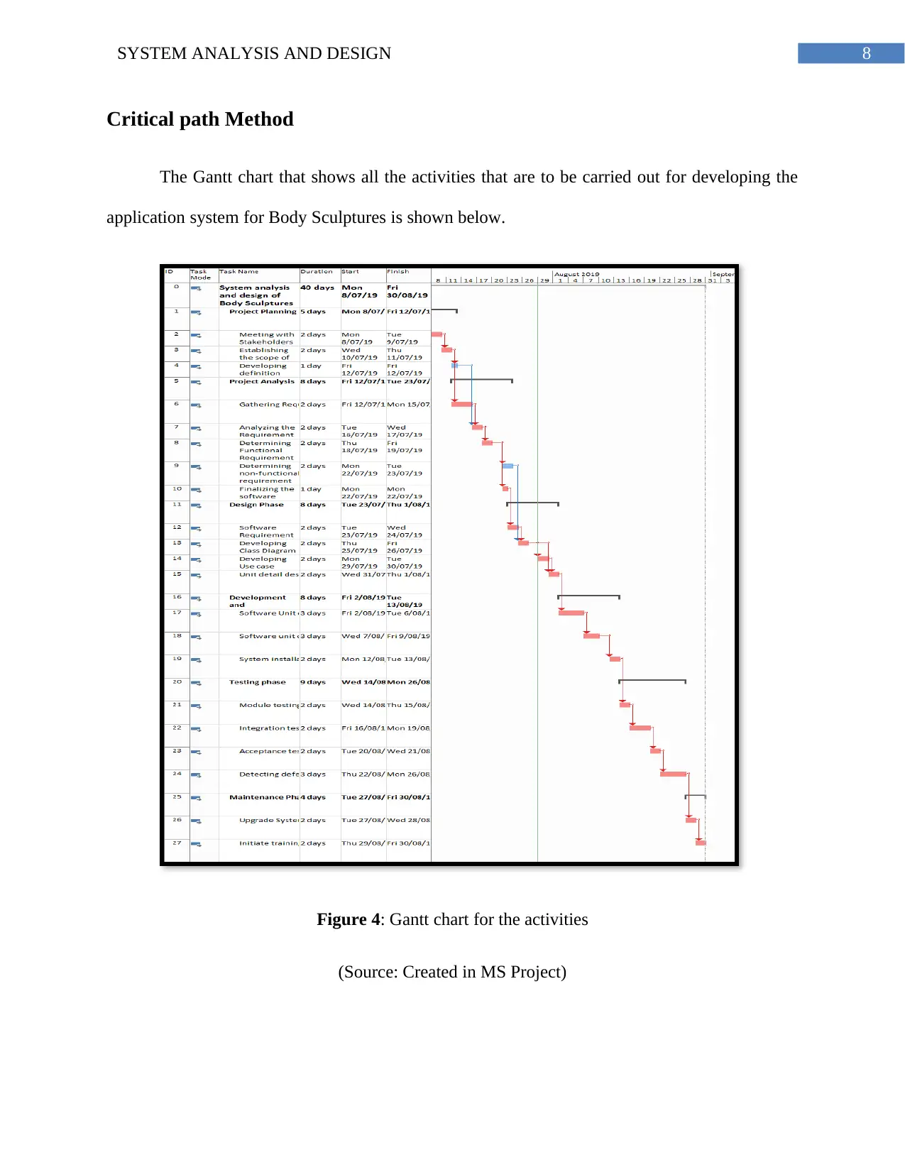
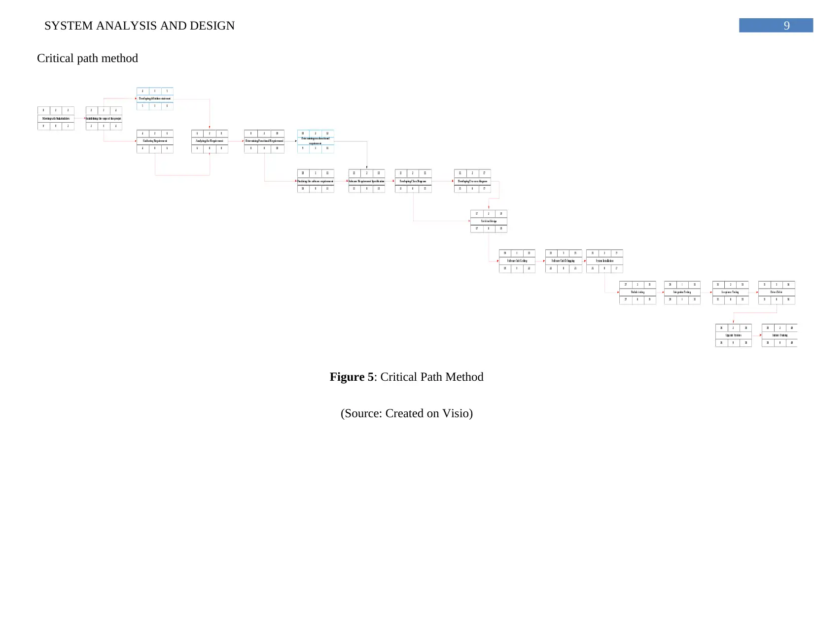
This project provides a comprehensive analysis and design of a system for Body Sculptures, utilizing the System Development Life Cycle (SDLC) methodology. It details the various stages of SDLC, including planning, analysis, design, development, testing, and maintenance. The project incorporates essential diagrams such as class diagrams and use case diagrams to visually represent the system's structure and functionality. Furthermore, it employs project management tools like Gantt charts and the Critical Path Method (CPM) to outline project activities, timelines, and dependencies. The analysis includes the application of formulas for calculating early start, early finish, late start, and late finish times, culminating in the identification of the critical path for project completion. The project also showcases the use of diagrams to illustrate the rostering system for managers and the registration process for members. Overall, the assignment provides a practical application of system analysis and design principles within a real-world business context, offering valuable insights into software development processes and project management techniques.
Document Page
Running head: SYSTEM ANALYSIS AND DESIGN
System Analysis and Design
Name of Student-
Name of University-
Author’s Note-
tabler-icon-diamond-filled.svg

Paraphrase This Document

Need a fresh take? Get an instant paraphrase of this document with our AI Paraphraser
Document Page
1SYSTEM ANALYSIS AND DESIGN
SDLC Processes
The method of system development life cycle enables the users to change a new
developed project to some operational project. This method is an iterative, multi stage process
that is structured in a synchronized way (Onat et al., 2017). This particular process is used for
design or model a framework that includes all technical as well as non-technical activities for
delivering quality system that helps to meet the business expectation or exceed the business
expectation. This process also helps to manage the decision making process. There is system
approach in SDLC method that is needed to describe the processes. This particular method is
basically followed when there is IT project development.
The technology is increasing at a rapid pace and the humans in this technological age are
becoming more dependent on the technology in their daily purposes. The development of
software are becoming more complicated because of the increasing demand and increasing
competition (Kjaer et al., 2016). The process that is involved in services of software
development includes some series of software development processes that are to be followed for
developing the software application. In the SDLC method of developing software, mainly six
steps are involved towards successful completion of developing the application. The six steps
that are followed in SDLC method are explained below:
1. Planning: The main purpose of planning is finding out scope of the problem
associated with the project undertaken and then determine the possible solutions. Without perfect
planning in a project, the project strengths and project weakness of a project are not possible to
determine (Sharma and Misra, 2017). The project flawlessness is initiated by project planning
and helps to affect the progress of the project positively.
Document Page
2SYSTEM ANALYSIS AND DESIGN
2. Analysis: Project analysis sis carried out mainly to analyse the project performance of
the software that is being analysed at different stages. In the analysis process various notes are
made regarding the requirement of the software (Abrahamsson et al., 2017). Analysis is very
important for developing the software project and proceed to the next step. In the analysis phase,
the team undertaking the project considers functional requirements that are required for the
project or developing a solution for the project. In this particular phase, the system analysis and
design takes place and to analyse the needs of all end users so that the expectation of the end
users are satisfied.
3. Design: The third phase in SDLC method is the design phase. This phase details all the
necessary specifications, the operations, as well as the features that helps to satisfy all the
functional requirement included in the new application system. The process that is involved in
services of software development includes some series of software development processes that
are to be followed for developing the software application. This phase is carried out only after
the analysis phase is being completed (Chowdhury et al., 2018). There are many steps that are
included in the designing process that helps to design the architecture of the new software or
application. All possible flaws that might occur while carrying out SDLC method are removed in
the phases by applying a standard for development.
4. Development and Implementation: The development phase is the initial section in
software development (Matharu et al., 2015). Development phase mainly signifies the starting of
the production. In the development stage there is a change and instillation that is being carried
out. In the development phase the data goes to the background of developing the software. Once
the development phase is being completed, the implementation phase starts. In the
implementation phase, the code and the program is written for developing the system (Shylesh,
Document Page
3SYSTEM ANALYSIS AND DESIGN
2017). In the implementation phase, all the data and the components are removed from previous
system and are placed in the new system or the data and components are newly made.
5. Testing: In the testing phase, the programs and the codes are tested for the errors or if
they have any have any bugs or not. In the testing phase of programs as well as the procedures,
the testing is actually carried out by the Quality analyst and by professionals of Quality
Assurance (Lindberg, Berente and Lyytinen, 2015). This helps to determine if the design that is
done for the system development meets initial stages of the business goals.
6. Maintenance: After passing through all the steps mentioned above without facing any
problems, then the system comes in maintenance process. In the maintenance process, the system
will be upgraded from one time to time and adapts all the changes that are new in the technology
(Fitzgerald and Stol, 2017). The testing phase mainly includes tuning of the system with the new
system adaptability and boost the performance of the system, add new capabilities in the system
and helps to meet the additional requirement of the user.
tabler-icon-diamond-filled.svg

Paraphrase This Document

Need a fresh take? Get an instant paraphrase of this document with our AI Paraphraser
Document Page
4SYSTEM ANALYSIS AND DESIGN
Class Diagram
Figure 1: Class diagram
(Source: Created by Author)
The diagram above shows the class diagram associated with the Body Sculptures. The
class diagram shows seven different class that relationship with each other. There is aggregation,
specialization, as well as composition relationship in between the classes. The classes are
associated with each other. There are attributes in the classes that states the members of the
classes.
Document Page
5SYSTEM ANALYSIS AND DESIGN
Use Case Diagram of Manager Schedules staff roster
Figure 2: Use Case Diagram
(Source: Created by Author)
The above use case diagram shows rostering system for the Body Sculptures. The body
sculptures has different timing and different types of classes are included in the gym. The
managers needs to roaster the trainers according to their speciality. The trainer has different
specialities and the manager has to roster so that in all the time slots, there has to be a specialists
in each slots. The trainer has different class timings and there has to be each type of trainer in
each time slots of the gym.
Use Case Diagram of Member Registers for class
Document Page
6SYSTEM ANALYSIS AND DESIGN
Figure 3: Use Case Diagram
(Source: Created by Author)
The above diagram shows the use case diagram of the members registering for the
system. For registering in the system, the members needs to enter the name, enter their address,
enter the date of birth and enter the contact number of the members so that they can be contacted.
The occupation of members are also to be mentioned by the members. The customer has two
types of access in the gym, full time members and restricted members. The full time members
included in the gym have access to all facilities as well as includes equipment that are present in
tabler-icon-diamond-filled.svg

Paraphrase This Document

Need a fresh take? Get an instant paraphrase of this document with our AI Paraphraser
Document Page
7SYSTEM ANALYSIS AND DESIGN
the centre. The restricted members can access to only some of the services as well as resources
that are nominated to them. The members also has to make payment in the basis of membership
they take. The membership card that is provided to the members are done on the payment of
payment and the subscription that are taken by the members. Classes are run by the trainers and
members are to attend the classes at the time allocated for the session.
Document Page
8SYSTEM ANALYSIS AND DESIGN
Critical path Method
The Gantt chart that shows all the activities that are to be carried out for developing the
application system for Body Sculptures is shown below.
Figure 4: Gantt chart for the activities
(Source: Created in MS Project)
Document Page
9SYSTEM ANALYSIS AND DESIGN
Critical path method
Figure 5: Critical Path Method
(Source: Created on Visio)
tabler-icon-diamond-filled.svg

Paraphrase This Document

Need a fresh take? Get an instant paraphrase of this document with our AI Paraphraser
Document Page
10SYSTEM ANALYSIS AND DESIGN
The above diagram states the critical path method that is required for completing the
application system for Body Sculptures. The CPM includes sequential activities that includes the
starting of the project and ending of the project (Brhel et al., 2015). The CPM method states the
scheduling activities that are required for completing the project. CPM method includes
preparation of the schedule and includes resource planning. The CPM is the longest stretch
including the activities as well as the total time needed for managing the time.
The above diagram that is state the total completion of time for the project is 40 days and
the path of activities that are shown in red shows the critical path of the project. There are two
activities in the project that does not comes under the critical path. The critical path shown above
shows the early start, early finish, late start, and late finish of the project. The diagram also
shows the slack of each activities. The formulas that are considered for calculating the project are
stated below.
EF = Early start of first activity + duration of the activity
ES = Early start of first activity (0) or early finish of previous activity
LS = Early finish of the activity - duration of the activity
LF = Early start of previous activity
Slack = Early Start –Late Start
All the above formulas are used for calculating the early start, early finish, late start and
late finish of the activities.
Document Page
11SYSTEM ANALYSIS AND DESIGN
The critical path is determined when the slack of a particular activity is zero that is if the
difference between early start and early finish is zero then the activity is known to be in critical
path and all those activities are to be included and are to be completed on time.
chevron_up_icon
1 out of 14
circle_padding
hide_on_mobile
zoom_out_icon
[object Object]