Report: System Analysis and Design - UML Diagrams and Evaluation
VerifiedAdded on 2021/01/02
|12
|1919
|200
Report
AI Summary
This report provides a comprehensive analysis of System Analysis and Design (SAD), focusing on the application of UML diagrams within the context of a tour management system. The report is divided into three parts, with the first part detailing the uses and construction of class and communication diagrams, including their application in the 'Record New Tour' scenario. It explains the structure and uses of class diagrams, highlighting their role in representing the static structure of a system and inter-relationships between classes. The second part explores sequence diagrams, explaining their use in defining the flow of logic within a system and their application in 'Record New Tour'. The third part evaluates the Enterprise Architect tool, highlighting its features and benefits for software design and UML diagram creation. The report concludes by discussing the role of a system analyst and referencing relevant sources.
System Analysis and Design
Paraphrase This Document
Need a fresh take? Get an instant paraphrase of this document with our AI Paraphraser
Table of Contents
PART 1............................................................................................................................................1
Class Diagram..............................................................................................................................1
Communication Diagram.............................................................................................................1
PART 2............................................................................................................................................2
Sequence Diagram.......................................................................................................................2
PART 3............................................................................................................................................2
Evaluation....................................................................................................................................2
REFERENCES ...............................................................................................................................5
PART 1
Class Diagram
a). Uses of the Analysis Class diagram in System Analysis and Design
This can also be termed as a Descendent of Entity-Relationship diagram which basically
helpful in describing the static structure of the model. UML Class Diagram is mainly used to
show the classes of the system which are involved in designing the functions of the system.
These functions are generally enclosed within a particular structure and also helps in performing
a particular attribute or action (Boussellaa, and Abed, 2015). It also helps in representing the
inter-relationship, their operations and also the attributes of different classes. The class Diagram
helps in accessing various things such as:
It helps in exploring the main concept of the domain in the form of domain model.
It also helps in analysing the requirements in the form of analysis model. The class diagram depicts the detailed design of object oriented or object-based designing
concept.
b). Class diagram for 'Record New Tour'
1
⊘ This is a preview!⊘
Do you want full access?
Subscribe today to unlock all pages.
Trusted by 1+ million students worldwide
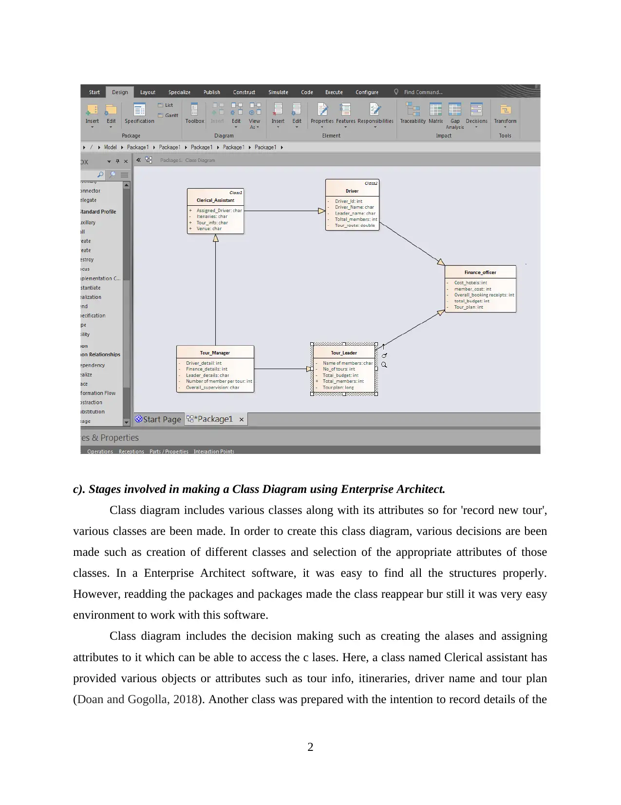
c). Stages involved in making a Class Diagram using Enterprise Architect.
Class diagram includes various classes along with its attributes so for 'record new tour',
various classes are been made. In order to create this class diagram, various decisions are been
made such as creation of different classes and selection of the appropriate attributes of those
classes. In a Enterprise Architect software, it was easy to find all the structures properly.
However, readding the packages and packages made the class reappear bur still it was very easy
environment to work with this software.
Class diagram includes the decision making such as creating the alases and assigning
attributes to it which can be able to access the c lases. Here, a class named Clerical assistant has
provided various objects or attributes such as tour info, itineraries, driver name and tour plan
(Doan and Gogolla, 2018). Another class was prepared with the intention to record details of the
2
Paraphrase This Document
Need a fresh take? Get an instant paraphrase of this document with our AI Paraphraser
trip and plan the budget named as finance officer. All the trips are allotted a proper leaders and
leader class contains the information about the details of the members.
Communication Diagram
a). Communication Diagram and its various uses in SAD
Communication diagram was basically introduced in Unified Modelling Language 2.0.
this diagram is mainly used to describe the interactions of two or more things in the System. The
Communication diagram can be further categorised into three parts such as:
Objects: It may be called as a Participants that are involved in performing activities.
The communication Link: This allows the flow of the message from one object to
another.
A message: It can be termed as the communicable message which is transformed from
one object to another via communication link.
Also, this diagram is used to show the same information as a sequence diagram but it may be
more difficult to read comparatively. It may lay emphasizes on the objects whereas sequence
diagram focuses on the Time Ordering of a message (Fernández-Sáez And et.al., 2015). This will
also helps to determine the path in which one object is linked with another.
b). Communication Diagram using Enterprise Architect tool.
3
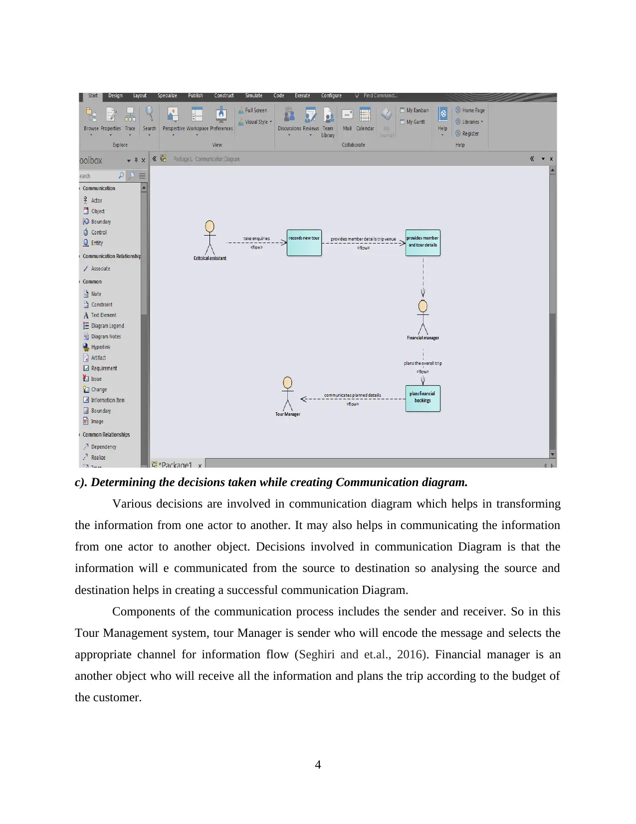
c). Determining the decisions taken while creating Communication diagram.
Various decisions are involved in communication diagram which helps in transforming
the information from one actor to another. It may also helps in communicating the information
from one actor to another object. Decisions involved in communication Diagram is that the
information will e communicated from the source to destination so analysing the source and
destination helps in creating a successful communication Diagram.
Components of the communication process includes the sender and receiver. So in this
Tour Management system, tour Manager is sender who will encode the message and selects the
appropriate channel for information flow (Seghiri and et.al., 2016). Financial manager is an
another object who will receive all the information and plans the trip according to the budget of
the customer.
4
⊘ This is a preview!⊘
Do you want full access?
Subscribe today to unlock all pages.
Trusted by 1+ million students worldwide
PART 2
Sequence Diagram
a). Description of Sequence Diagram and its various uses in SAD
Unified Modelling Language is mainly helps in defining the flow of logic within the
system in a visual manner. This also enables to document and validate the the logics of
programming the system. This can also be considered as one of the most popular diagram that
mainly focuses in identifying the behaviour of the model within the system. In order to develop a
modern business application, one of the most preferable design is sequence diagram along with
class and physical Data Models. Sequence Diagram are generally used to model different types
of services such as:
Usage scenarios: This helps in describing the various potential ways in which the system
is being used. The logic of the usage scenario may be a part of use case. This is also helps
in describing the basic course of action.
The Logics of the methods: Sequence Diagram is mainly used to explore the logics of the
complexed operations, functions or procedure (Sellami and et.al., 2015). Sequence
Diagram can also be called as a highly detailed diagram that also represents the Visual
object code. The Logic of Services: it is effectively high-level method which may be invoked by a
large variety of methods.
b). Sequence Diagram for 'Record new tour'
5
Paraphrase This Document
Need a fresh take? Get an instant paraphrase of this document with our AI Paraphraser
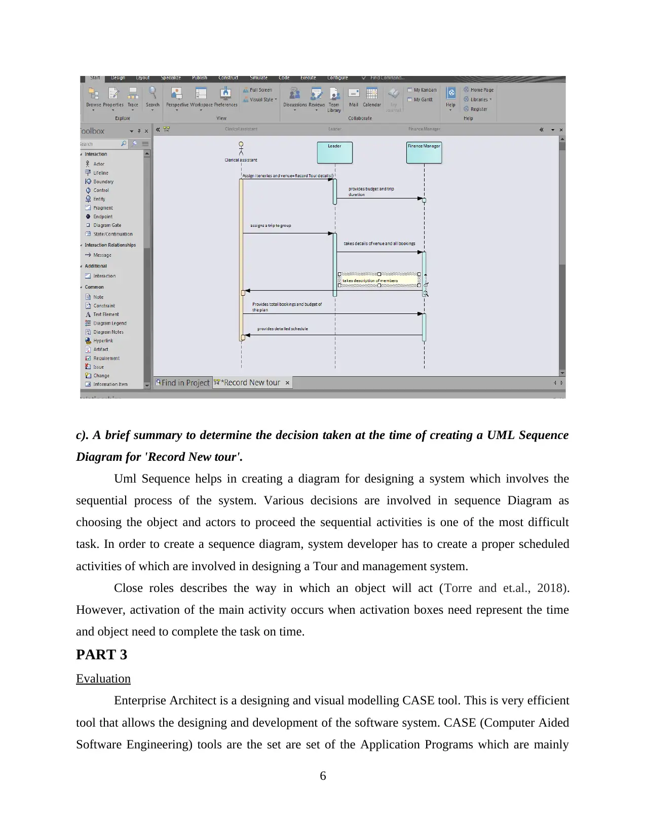
c). A brief summary to determine the decision taken at the time of creating a UML Sequence
Diagram for 'Record New tour'.
Uml Sequence helps in creating a diagram for designing a system which involves the
sequential process of the system. Various decisions are involved in sequence Diagram as
choosing the object and actors to proceed the sequential activities is one of the most difficult
task. In order to create a sequence diagram, system developer has to create a proper scheduled
activities of which are involved in designing a Tour and management system.
Close roles describes the way in which an object will act (Torre and et.al., 2018).
However, activation of the main activity occurs when activation boxes need represent the time
and object need to complete the task on time.
PART 3
Evaluation
Enterprise Architect is a designing and visual modelling CASE tool. This is very efficient
tool that allows the designing and development of the software system. CASE (Computer Aided
Software Engineering) tools are the set are set of the Application Programs which are mainly
6
used to function the SDLC activities of the system. These tools are generally used by various
software developers and engineers in order to develop a software for the system. These tools are
also used by different organisations in order to implement the process model for the development
of application life-cycle along with the modelling of architecture in the system.
Enterprise architect Tool is used by World wide Tour Management system in order to
design a system that helps the organisation in increasing their operational as well as business
efficiency to record new Tour. These CASE tools are partially inspired by CAD tools that are
used to design hardware products. It can also be used in creating different UML diagrams for the
development of the software and designs. This is used to design the applications that helps in
world Tour Management company to develop different modules using UML diagrams in System
Architect. Such UML diagram may includes various diagrams such as Class, communication,
Sequence, Activity etc. CASE tool is also helpful in visualizing the design of the software. Ot
may be vary according to the structure, behaviour and interaction between the functional and
operational tasks. System and software development may includes various kinds of methods and
the stages which contributes towards the development of the software can be called as the SDLC
phases (System development Life cycle).
CASE tool offers an excellent array of features that are used to support the development
and business community through its Automated diagram support Features. Various popular
features that are used to develop the system and analysis design (Torre and et.al., 2018). Such
features are Syntactic correctness, Data dictionary support, completeness and consistency,
Requirement traceability, system simulation, performance Analysis etc.
System Analysts acts as a Outside consultant to World wide Tour Management System
and also supports experts within the business. Role of Analyst in developing and designing a
system software includes problem solving skills, communication skills etc. also the Analyst need
to be ethical with users and customers. The Job of the system Analyst may contains the
requirements Analysis, process design and programming. So CASE tools provides various
efficient techniques to analyst in order to perform efficient operations hence these tools supports
the functional efficiency of the Analyst as it helps in designing and developing the system
software design (Constructing UML Diagram., 2016).
UML modelling supports the Analysts as it provides different types of architectural
designs to support their the designing and development of the system. UML provides various
7
⊘ This is a preview!⊘
Do you want full access?
Subscribe today to unlock all pages.
Trusted by 1+ million students worldwide

diagrams in order to implement the architecture of the the system. Such diagrams includes the
following class diagram, Sequence Diagram, activity diagram, communication Diagram etc.
8
following class diagram, Sequence Diagram, activity diagram, communication Diagram etc.
8
Paraphrase This Document
Need a fresh take? Get an instant paraphrase of this document with our AI Paraphraser
REFERENCES
Books and journals
Boussellaa, A. and Abed, M., 2015, October. Information system design for reverse logistics
management using UML. In Industrial Engineering and Systems Management
(IESM), 2015 International Conference on (pp. 1230-1239). IEEE.
Doan, K.H. and Gogolla, M., 2018, June. Logical Reasoning with Object Diagrams in a UML
and OCL Tool. In International Conference on Theory and Application of
Diagrams (pp. 774-778). Springer, Cham.
Fernández-Sáez, A.M. And et.al., 2015. Are Forward Designed or Reverse-Engineered UML
diagrams more helpful for code maintenance?: A family of experiments. Information
and Software Technology. 57. pp.644-663.
Seghiri, R. and et.al., 2016, January. An executable model driven framework for enterprise
architecture application to the Smart Grids context. In System Sciences (HICSS),
2016 49th Hawaii International Conference on (pp. 4546-4555). IEEE.
Sellami, A. and et.al., 2015. A measurement method for sizing the structure of UML sequence
diagrams. Information and Software Technology. 59. pp.222-232.
Torre, D. and et.al., 2018. A systematic identification of consistency rules for UML
diagrams. Journal of Systems and Software.
Online
Constructing UML Diagram. 2016. [online] Available Through : <
https://sourcemaking.com/uml/modeling-it-systems/interaction-view/constructing-
communication-diagrams>
9

10
⊘ This is a preview!⊘
Do you want full access?
Subscribe today to unlock all pages.
Trusted by 1+ million students worldwide
1 out of 12
Related Documents


Your All-in-One AI-Powered Toolkit for Academic Success.
+13062052269
info@desklib.com
Available 24*7 on WhatsApp / Email
![[object Object]](/_next/static/media/star-bottom.7253800d.svg)
Unlock your academic potential
Copyright © 2020–2026 A2Z Services. All Rights Reserved. Developed and managed by ZUCOL.