System Analysis and Design: Modelling Assignment for IMAT5205 Module
VerifiedAdded on 2023/04/21
|12
|2551
|83
Report
AI Summary
This report presents a detailed analysis of a system design project, focusing on the 'Record New Tour' use case within a Wide World Tour Management System. The analysis utilizes Unified Modeling Language (UML) diagrams, including class, communication, and sequence diagrams, to model the system's structure and behavior. The class diagram identifies classes, attributes, and operations, while the communication diagram illustrates object interactions and message sequences. The sequence diagram further elaborates on the message flow and object lifelines. The report also evaluates the use of the Enterprise Architect CASE tool for generating these diagrams, highlighting its role in supporting the system analysis and design process. The report emphasizes the effective application of UML diagrams in capturing the structural and behavioral patterns of the system, facilitating a clear understanding of the application's elements and their interactions. The author has demonstrated the ability to translate business requirements into technical specifications, using the CASE tool to streamline the modeling process and ensure a well-structured system design.

Running head: SYSTEM ANALYSIS AND DESIGN
System Analysis and Design
Name of the Student
Name of the University
Author’s note:
System Analysis and Design
Name of the Student
Name of the University
Author’s note:
Paraphrase This Document
Need a fresh take? Get an instant paraphrase of this document with our AI Paraphraser

1SYSTEM ANALYSIS AND DESIGN
Table of Contents
Part 1: Use Case Realisation for the ‘Record New Tour’ Use Case...........................................2
1.1 Analysis Class Diagram:..................................................................................................2
1.2 Communication Diagram:................................................................................................3
Part 2: Sequence Diagram..........................................................................................................4
Part 3: Evaluation.......................................................................................................................6
Bibliography:..............................................................................................................................8

2SYSTEM ANALYSIS AND DESIGN
Part 1: Use Case Realisation for the ‘Record New Tour’ Use Case
1.1 Analysis Class Diagram:
Unified modelling language (UML) can be divided into various versions and
class diagram can be included among them. Class diagram is usually developed in
order to identify classes of attributes, operations and applications of every class. Class
diagram is generally static in nature.
Class diagram is utilized in the process of system analysis in order to describe as well
as identify the vocabulary of the application. Various diagrams like communication
diagram, sequence diagram and some more diagrams are developed on the basis of
class diagrams. Class diagram consists of various operations that are assisting in
nature when it comes to describing the way system would process.
Figure 1: Wide World Tour Management SystemClass Diagram
⊘ This is a preview!⊘
Do you want full access?
Subscribe today to unlock all pages.
Trusted by 1+ million students worldwide

3SYSTEM ANALYSIS AND DESIGN
(Source: Created by Author)
As per the figure 1 that has been provided above, three classes are present in class
diagram. According to the description of ‘Record New Tour’, both the classes would be
enough in order to create a new tour record. The two classes had depicted the driver’s
vocabulary and tour section of application. Tour class consists of various attributes like
tourCategory, tourID, tourStartDate, tourEndDate, tourStartTime and tourLocation. The
tourID can be defined as a specific attribute which stores a unique value for any data set that
is entered in the class. The tourID can be utilized in order to identify the rows of information
in a separate manner. This sort of attributes is situated in different classes like the one in the
driver class is called as driverID, in case of the clerical assistant class it is called caID. Every
class have their particular set of operations. Every operation is public for the purpose that the
application would be able to utilize the operations in an effective manner at necessary places.
1.2 Communication Diagram:
System object management is considered as an important part of a specific application
that is object oriented. The collaboration diagram gives support to developer while drawing a
diagram for the purpose of showing object management. Numbering patterns are used in
order to showcase the sequence of messages. When the number increases, the next message
in the queue is called. The messages can be defined as the operations that have been defined
in every class.
The communication time has been drawn in order to identify the flow of various
messages in the provided application with respect to the sequence of time. The diagram
supports in creating as well as identifying the structural management for the messages’ flow
in the URL domain.
Paraphrase This Document
Need a fresh take? Get an instant paraphrase of this document with our AI Paraphraser

4SYSTEM ANALYSIS AND DESIGN
Figure 2: Communication Diagram of Wide World Tour Management System
(Source: Created by Author)
Clerical assistant would be responsible in initializing the operation of recording a data
of new tour with the help of recordNewTour(), this has been mentioned through its object.
Class consists of the recordNewTour() method, the clerical assistant would be the object that
would be called at first. After starting the operation, system would help in collecting data
regarding the tour object’s class. System would require an input for the attributes that would
be available in tour class. At first the details of the tour are confirmed, after that the system
would assign a specific driver for the tour. The objects of various classes are represented or
understood through rectangles. The rectangles that have been provided are usually connected
with the help of a line. Every line consists of a message with a specific direction that denotes
the object from where message is going.
Part 2: Sequence Diagram
Sequence diagram is one of the most popular UML tool. It consists of objects, lifeline,
messages, elements and many more. The operations present in the classes can be considered
as messages present in a specific sequence diagram. System diagram is used in capturing
system behaviour. The reason of sequence diagram is capable of tracking the calling of the
object that can be denoted as the messages in a sequence diagram. Use case diagrams can be
considered as the basic of sequence diagram and not the class diagram in case the description
of the provided case is provided properly.
5SYSTEM ANALYSIS AND DESIGN
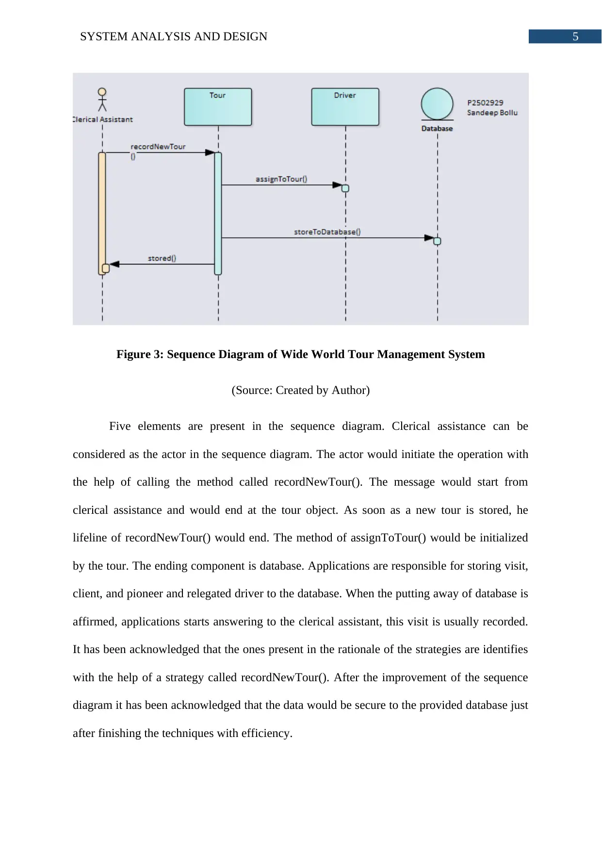
Figure 3: Sequence Diagram of Wide World Tour Management System
(Source: Created by Author)
Five elements are present in the sequence diagram. Clerical assistance can be
considered as the actor in the sequence diagram. The actor would initiate the operation with
the help of calling the method called recordNewTour(). The message would start from
clerical assistance and would end at the tour object. As soon as a new tour is stored, he
lifeline of recordNewTour() would end. The method of assignToTour() would be initialized
by the tour. The ending component is database. Applications are responsible for storing visit,
client, and pioneer and relegated driver to the database. When the putting away of database is
affirmed, applications starts answering to the clerical assistant, this visit is usually recorded.
It has been acknowledged that the ones present in the rationale of the strategies are identifies
with the help of a strategy called recordNewTour(). After the improvement of the sequence
diagram it has been acknowledged that the data would be secure to the provided database just
after finishing the techniques with efficiency.
⊘ This is a preview!⊘
Do you want full access?
Subscribe today to unlock all pages.
Trusted by 1+ million students worldwide
6SYSTEM ANALYSIS AND DESIGN
Part 3: Evaluation
Enterprise architect is considered as the CASE tool that has been used in the report.
EA toll is used for generating communication, sequence and class diagrams. Case tool
helps in supporting more than the diagrams mentioned. The tools are allowed to
support the communication technology and information project that has been
undertaken by any organization. The EA case tool or enterprise architect can be
considered as a set of specialized software application. These application units help in
evaluating the business and technical requirements of a specific organization like
Wide World Tour Management System.
Enterprise Architect Case Tool provides simple environment and modification in
techniques after the framework is examined and structured. The illustrations were perfectly
made after some happenings of shifting the innermost fragments of application in various
UML diagrams. Class diagram was made at first. Few pars of sequence diagrams are made in
the light of discoveries in the concept of class diagram. Part diagram represents the sequence
in which messages are sent in the application that had been proposed. The creators had
effectively adjusted business prerequisites to necessities that have been specialized. Using the
case instrument, the assessment of UML diagrams have been done.
The basic help that the creators and examiner of framework would get from case
apparatus is the entire spotlight on the proposed application’s architecture. The case
apparatus of enterprise architecture enables a simple procedure for coordinating crisp
necessities in the use case of ‘include new visit’. The architects might help in concentrating
on the structure of UML diagrams; this has been opposed to agonize on the way the case
instrument is used. This was considered as very critical because the creators were provided
with additional chance to halt and plot the diagrams instead of verdict out regarding
enterprise architecture. The instrument case of EA has an easy to use module of user
Paraphrase This Document
Need a fresh take? Get an instant paraphrase of this document with our AI Paraphraser

7SYSTEM ANALYSIS AND DESIGN
communication which benefits in authorizing the development of illustrations in an operative
manner. Generating the class diagram is simple and the last diagram was very detailed.
Including various attributes and the characterization of operations was very simple. The case
apparatus provides unpretentious alterations. The case apparatus provides simple methods for
building interface for a part diagram a well a sequence diagram. All the diagrams were made
with precision so that basic as well as dynamic parts of framework can be caught in a
flawless manner. It provided an ideal environment for catching as well as planning of the bits
of knowledge of business procedure.
The UML or Unified Modelling Language Diagrams are very crucial for system
analyst as various types of the UML diagrams can collect the structural or behavioural
patterns of Wide World Tour Management System. The first task of the report was to create
the class diagram to capture the required classes and elements of classes to record a new tour.
As the class diagram is a structural model, it greatly assisted in finding the data set and
operations that will process those data set. The class diagram provided the base for moving
forward to identifying the sequence in which the Wide World Tour Management System will
execute its operations.The communication diagram was the first step toward it. The
communication diagram provided the understanding of how the objects of the classes will
interact with other and in which time sequence. This is very important as the application must
call operations in a sequence. Otherwise, the application may fail to provide critical data to
one operation after it starts. The sequence diagram helped in understanding the message
sequence in a much depth manner. The sequence diagram was able to provide the
understanding of lifeline of each message.
The utilization of the UML diagrams has really shown how the structural and
behavioural patterns of Wide World Tour Management System. It was very easy to capture
the elements of the application through the UML diagrams. From the elements of each class

8SYSTEM ANALYSIS AND DESIGN
to the utilization of individual elements of the classes are perfectly understood through the
UML diagrams.
to the utilization of individual elements of the classes are perfectly understood through the
UML diagrams.
⊘ This is a preview!⊘
Do you want full access?
Subscribe today to unlock all pages.
Trusted by 1+ million students worldwide

9SYSTEM ANALYSIS AND DESIGN
Bibliography:
Baumann, P., Hahn, T. and Hubbuch, J., 2015. High‐throughput micro‐scale cultivations and
chromatography modeling: Powerful tools for integrated process development.
Biotechnology and bioengineering, 112(10), pp.2123-2133.
Bryman, A. and Bell, E., 2015. Business research methods. Oxford University Press, USA.
Cengarle, M.V., Grönninger, H. and Rumpe, B., 2014. System model semantics of class
diagrams. arXiv preprint arXiv:1409.6635.
Clark, W.C., Tomich, T.P., Van Noordwijk, M., Guston, D., Catacutan, D., Dickson, N.M.
and McNie, E., 2016. Boundary work for sustainable development: Natural resource
management at the Consultative Group on International Agricultural Research (CGIAR).
Proceedings of the National Academy of Sciences, 113(17), pp.4615-4622.
Da Silva, A.R., 2015. Model-driven engineering: A survey supported by the unified
conceptual model. Computer Languages, Systems & Structures, 43, pp.139-155.
Dabbagh, M. and Lee, S.P., 2014. An approach for integrating the prioritization of functional
and nonfunctional requirements. The Scientific World Journal, 2014.
Deeba, F., Kun, S., Shaikh, M., Dharejo, F.A., Hayat, S. and Suwansrikham, P., 2018, April.
Data transformation of UML diagram by using model driven architecture. In 2018 IEEE 3rd
International Conference on Cloud Computing and Big Data Analysis (ICCCBDA) (pp. 300-
303). IEEE.
Dumais, S., Cutrell, E., Cadiz, J.J., Jancke, G., Sarin, R. and Robbins, D.C., 2016, January.
Stuff I've seen: a system for personal information retrieval and re-use. In ACM SIGIR Forum
(Vol. 49, No. 2, pp. 28-35). ACM.
Paraphrase This Document
Need a fresh take? Get an instant paraphrase of this document with our AI Paraphraser

10SYSTEM ANALYSIS AND DESIGN
Eckhardt, J., Vogelsang, A. and Fernández, D.M., 2016. Are" Non-functional" Requirements
really Non-functional? An Investigation of Non-functional Requirements in Practice. In
Software Engineering (ICSE), 2016 IEEE/ACM 38th International Conference on (pp. 832-
842). IEEE.
Ilieva-Obretenovaa, M., 2016. Information System Functions for SmartGrid Management.
Sociology, 6(2), pp.96-103.
Khan, S., Babar, M., Khan, F., Arif, F. and Tahir, M., 2016. Collaboration Methodology for
Integrating Non-Functional Requirements in Architecture. the Journal of Applied
Environmental and Biological Sciences (JAEBS), 6, pp.63-67.
Koller, M., Vadlja, D., Braunegg, G., Atlić, A. and Horvat, P., 2017. Formal-and high-
structured kinetic process modelling and footprint area analysis of binary imaged cells: Tools
to understand and optimize multistage-continuous PHA biosynthesis. The EuroBiotech
Journal, 1(3), pp.203-211.
Lazar, J., Feng, J.H. and Hochheiser, H., 2017. Research methods in human-computer
interaction. Morgan Kaufmann.
Rahman, M. and Ripon, S., 2014. Elicitation and modeling non-functional requirements-a
POS case study. arXiv preprint arXiv:1403.1936.
Ricci, F., Rokach, L. and Shapira, B., 2015. Recommender systems: introduction and
challenges. In Recommender systems handbook (pp. 1-34). Springer, Boston, MA.
Stanton, N.A., Salmon, P.M., Rafferty, L.A., Walker, G.H., Baber, C. and Jenkins, D.P.,
2017. Human factors methods: a practical guide for engineering and design. CRC Press.

11SYSTEM ANALYSIS AND DESIGN
Thum, T., Kastner, C., Benduhn, F., Meinicke, J., Saake, G. and Leich, T., 2014. FeatureIDE:
An extensible framework for feature-oriented software development. Science of Computer
Programming, 79, pp.70-85.
Wichmann, A., Jäger, S., Jungebloud, T., Maschotta, R. and Zimmermann, A., 2016, April.
Specification and execution of system optimization processes with UML activity diagrams.
In Systems Conference (SysCon), 2016 Annual IEEE (pp. 1-7). IEEE.
⊘ This is a preview!⊘
Do you want full access?
Subscribe today to unlock all pages.
Trusted by 1+ million students worldwide
1 out of 12
Related Documents


Your All-in-One AI-Powered Toolkit for Academic Success.
+13062052269
info@desklib.com
Available 24*7 on WhatsApp / Email
![[object Object]](/_next/static/media/star-bottom.7253800d.svg)
Unlock your academic potential
Copyright © 2020–2026 A2Z Services. All Rights Reserved. Developed and managed by ZUCOL.