IMAT5205: System Analysis and Design Report on Tour Management System
VerifiedAdded on 2023/04/20
|11
|2173
|196
Report
AI Summary
This report provides a detailed system analysis and design for a tour management system, covering use case realization for the 'Record New Tour' use case. It includes an analysis class diagram, demonstrating the concepts and attributes of the system, along with a communication diagram illustrating the interactions between actors and objects. A sequence diagram further visualizes the message flow within the system. The report also evaluates the system using CASE tools, highlighting their benefits in system development, such as reduced development time, cost reduction, and support for various functionalities like requirement tracing and system layering. The report concludes with a bibliography of relevant sources.
Running head: SYSTEM ANALYSIS AND DESIGN
SYSTEM ANALYSIS AND DESIGN
Name of the student
Name of the university
Author Note
SYSTEM ANALYSIS AND DESIGN
Name of the student
Name of the university
Author Note
Paraphrase This Document
Need a fresh take? Get an instant paraphrase of this document with our AI Paraphraser
1
SYSTEM ANALYSIS AND DESIGN
Table of Contents
Part 1. Use Case Realisation for the ‘Record New Tour’ Use Case.......................................................2
Analysis Class Diagram.....................................................................................................................2
Communication diagram...................................................................................................................3
Part2: Sequence Diagram......................................................................................................................4
Part 3: Evaluation..................................................................................................................................6
Bibliography..........................................................................................................................................9
2
SYSTEM ANALYSIS AND DESIGN
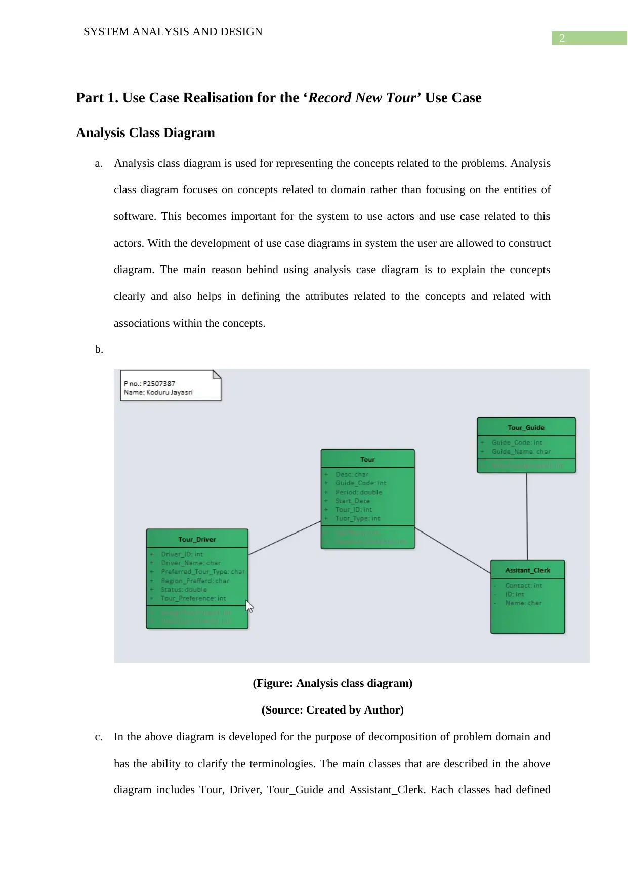
Part 1. Use Case Realisation for the ‘Record New Tour’ Use Case
Analysis Class Diagram
a. Analysis class diagram is used for representing the concepts related to the problems. Analysis
class diagram focuses on concepts related to domain rather than focusing on the entities of
software. This becomes important for the system to use actors and use case related to this
actors. With the development of use case diagrams in system the user are allowed to construct
diagram. The main reason behind using analysis case diagram is to explain the concepts
clearly and also helps in defining the attributes related to the concepts and related with
associations within the concepts.
b.
(Figure: Analysis class diagram)
(Source: Created by Author)
c. In the above diagram is developed for the purpose of decomposition of problem domain and
has the ability to clarify the terminologies. The main classes that are described in the above
diagram includes Tour, Driver, Tour_Guide and Assistant_Clerk. Each classes had defined
SYSTEM ANALYSIS AND DESIGN
Part 1. Use Case Realisation for the ‘Record New Tour’ Use Case
Analysis Class Diagram
a. Analysis class diagram is used for representing the concepts related to the problems. Analysis
class diagram focuses on concepts related to domain rather than focusing on the entities of
software. This becomes important for the system to use actors and use case related to this
actors. With the development of use case diagrams in system the user are allowed to construct
diagram. The main reason behind using analysis case diagram is to explain the concepts
clearly and also helps in defining the attributes related to the concepts and related with
associations within the concepts.
b.
(Figure: Analysis class diagram)
(Source: Created by Author)
c. In the above diagram is developed for the purpose of decomposition of problem domain and
has the ability to clarify the terminologies. The main classes that are described in the above
diagram includes Tour, Driver, Tour_Guide and Assistant_Clerk. Each classes had defined
⊘ This is a preview!⊘
Do you want full access?
Subscribe today to unlock all pages.
Trusted by 1+ million students worldwide
3
SYSTEM ANALYSIS AND DESIGN
with certain entities. The main entities of Driver class are Driver_ID, Driver_Name,
Preferred_Tour_Type, Status, Tour_Preference. Status entity of Driver class helps in checking
whether driver is available or not. Status of drivers can be checked with in the system by
using ViewTourDrivers(). Apart from this the Tour class is used to store several details
related to tour. In this class there are two methods that are used to add details about tour. The
Assistant_Clerk class is able to store the details with the method. The other class present in
the system is Tour_Guide that contains the leader name and id number. Once the system
identifies a free driver with the use of method ViewTourDrivers() , the driver is assigned to
lead the tour.
Communication diagram
a. The benefit of having a communication diagram is that it is used for providing extension to
the object diagram and helps the system to display the messages sent from one point to
another. Apart from this, with the help of communication diagram the messages associated
with each objects can be exchanged and also gets displayed. This diagrams are also known as
collaboration diagrams. This focuses on maintaining a proper relationship between the objects
and provides an interactive illustration similar to the sequence diagrams. The diagrams are
hence used to display the objects and the association developed between them.
Paraphrase This Document
Need a fresh take? Get an instant paraphrase of this document with our AI Paraphraser
4
SYSTEM ANALYSIS AND DESIGN
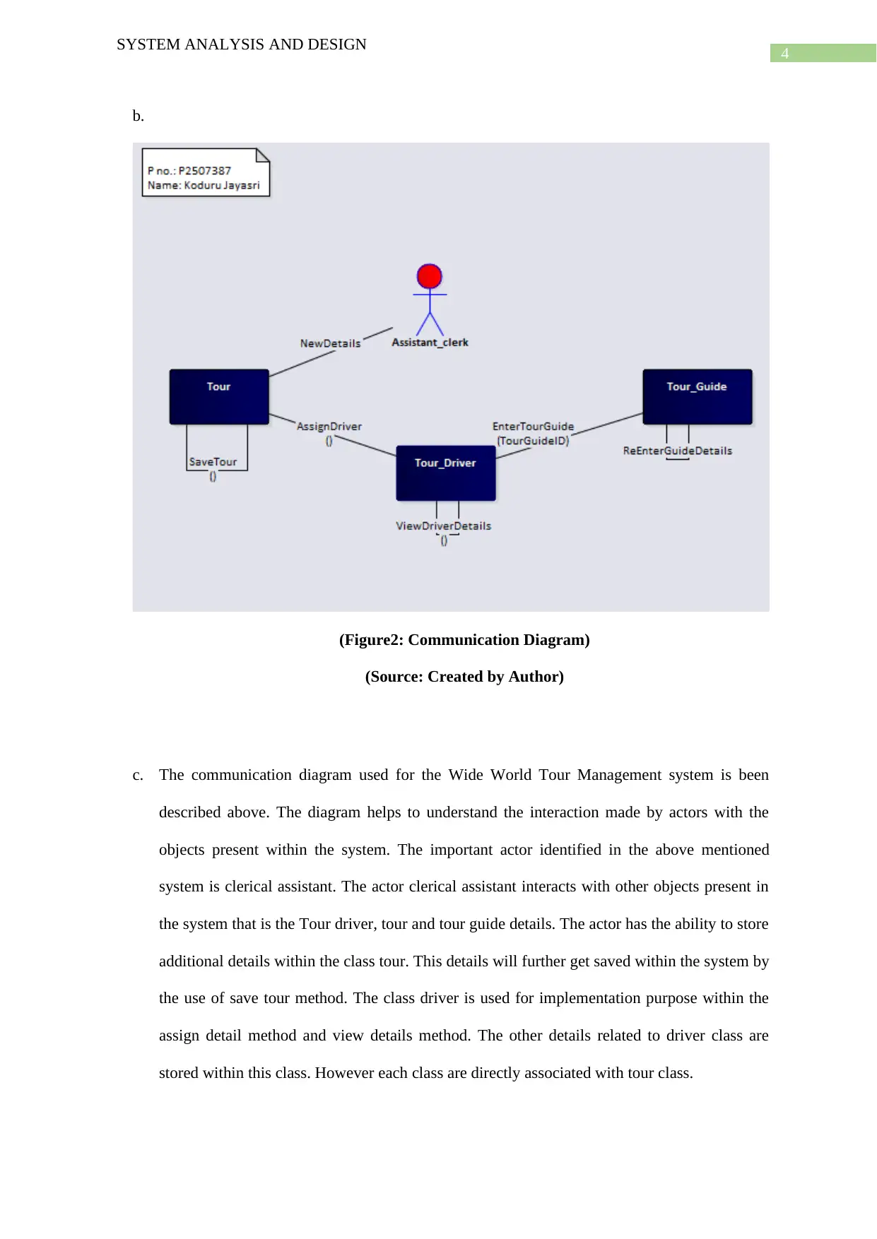
b.
(Figure2: Communication Diagram)
(Source: Created by Author)
c. The communication diagram used for the Wide World Tour Management system is been
described above. The diagram helps to understand the interaction made by actors with the
objects present within the system. The important actor identified in the above mentioned
system is clerical assistant. The actor clerical assistant interacts with other objects present in
the system that is the Tour driver, tour and tour guide details. The actor has the ability to store
additional details within the class tour. This details will further get saved within the system by
the use of save tour method. The class driver is used for implementation purpose within the
assign detail method and view details method. The other details related to driver class are
stored within this class. However each class are directly associated with tour class.
SYSTEM ANALYSIS AND DESIGN
b.
(Figure2: Communication Diagram)
(Source: Created by Author)
c. The communication diagram used for the Wide World Tour Management system is been
described above. The diagram helps to understand the interaction made by actors with the
objects present within the system. The important actor identified in the above mentioned
system is clerical assistant. The actor clerical assistant interacts with other objects present in
the system that is the Tour driver, tour and tour guide details. The actor has the ability to store
additional details within the class tour. This details will further get saved within the system by
the use of save tour method. The class driver is used for implementation purpose within the
assign detail method and view details method. The other details related to driver class are
stored within this class. However each class are directly associated with tour class.
5
SYSTEM ANALYSIS AND DESIGN
Part2: Sequence Diagram
a. The use of sequence diagram is depicting the interaction going on within different objects.
The flow within the message is being presented in the diagram. This messages are illustrated
in the diagram. The messages delivered are used to describe the communication and process
taking place within the system. The flow of messages and communications taking place
within the system has been depicted effectively for better understanding. Interactive diagrams
are further used to classify the sequence diagram. The purpose of using this is that it helps in
providing a better virtualization of the developed business while presenting the developing
system by the designers. Developers has the capability to identify the objects within the
system and the actors involved in the system.
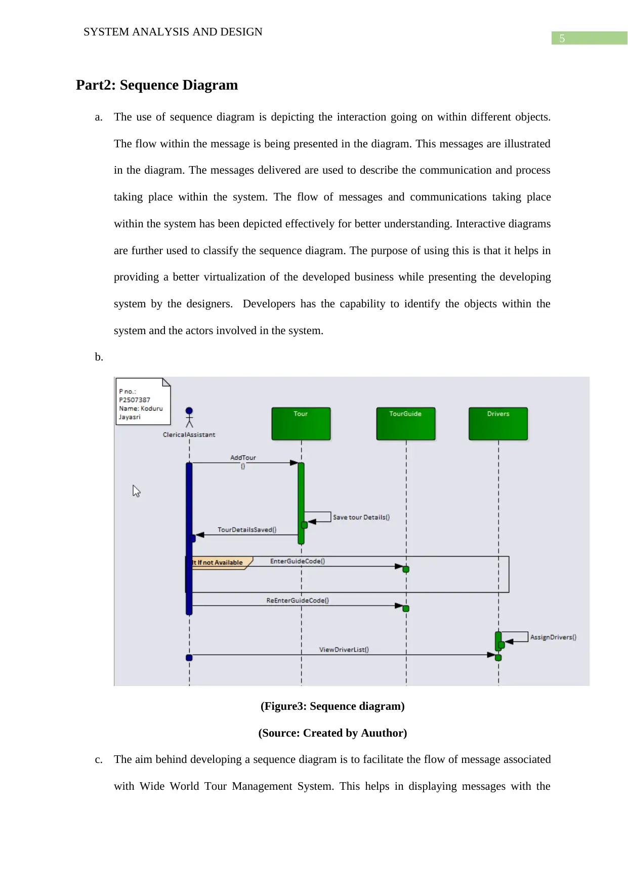
b.
(Figure3: Sequence diagram)
(Source: Created by Auuthor)
c. The aim behind developing a sequence diagram is to facilitate the flow of message associated
with Wide World Tour Management System. This helps in displaying messages with the
SYSTEM ANALYSIS AND DESIGN
Part2: Sequence Diagram
a. The use of sequence diagram is depicting the interaction going on within different objects.
The flow within the message is being presented in the diagram. This messages are illustrated
in the diagram. The messages delivered are used to describe the communication and process
taking place within the system. The flow of messages and communications taking place
within the system has been depicted effectively for better understanding. Interactive diagrams
are further used to classify the sequence diagram. The purpose of using this is that it helps in
providing a better virtualization of the developed business while presenting the developing
system by the designers. Developers has the capability to identify the objects within the
system and the actors involved in the system.
b.
(Figure3: Sequence diagram)
(Source: Created by Auuthor)
c. The aim behind developing a sequence diagram is to facilitate the flow of message associated
with Wide World Tour Management System. This helps in displaying messages with the
⊘ This is a preview!⊘
Do you want full access?
Subscribe today to unlock all pages.
Trusted by 1+ million students worldwide
6
SYSTEM ANALYSIS AND DESIGN
other elements associated with Wide World Tour Management System. The actor of the
system is Clerical assistant. This is responsible for interacting with other objects present
within the system. The system includes Drivers, Tours and Tour Guide as the object. The
main role of this actor is to add details related to tour, saving them for future interactions
within the system. Once the tour gets added to system the driver list is being displayed by the
system and the driver’s details with their availability can be viewed and the driver gets
allocated to specific tour. Moreover the details of driver includes guide number that gets
linked with every tour started by them.
Part 3: Evaluation
Enterprise architecture is the CASE tool use in developing the systems within this report.
Case tools are the abbreviation of Computer Aided Software Engineering technologies. This tool
helps in providing a brief description about the diverse type o functionalities used within the system.
The benefit of using a case tool is that it helps in providing support towards the description used in
this system. Each description also includes proper illustration for better visualization of the system
and helps the designer to develop a system after efficiently analysing the requirements.
The Computer Aided Software Engineering technologies will help in providing a better
assistance towards the developed software for Wide World Tour Management System. The benefit
achieved while using Computer Aided Software Engineering technologies tool is that it minimizes the
development time and also reduces the cost incorporated while developing a system. This develops a
system after analysing the organizations requirements. There are several more features offered by
Computer Aided Software Engineering technologies tools that are beneficial for system analyst. This
includes:
CASE tools provides the feature for tracing the requirements within the system
System layering is done with CASE tools
CASE tool provides data dictionary option for the system
CASE tool allows checking the syntax developed in the system
Paraphrase This Document
Need a fresh take? Get an instant paraphrase of this document with our AI Paraphraser

7
SYSTEM ANALYSIS AND DESIGN
Consistency and completeness can be maintained
CASE tool helps in aiding the problems
Performance of the system can be analysed with the use of CASE tools
Report for the developed system gets automatically generated with the use of CASE tools
Computer Aided Software engineering technologies tools are useful for system analyst and
helps in efficiently developing the system. The Computer Aided Software Engineering technologies
aims at providing better supports that are computer based and helps in developing the software
process within the system. This also facilitates proper analysis and support at the development time of
system and at the time of integration. With the implementation of this procedure the developer can
display the integrated system in front of their customer. From the point of view of an analyst it will
enhance the functions used in the system and encompasses the functions efficiently for better results.
The aim is to improve the functionality from each aspect of the system.
Computer Aided Software engineering tool facilitates the system by improving the
organization feature. This are done systematically in a stepwise manner. This can be identified by
analysing the steps taken by an analyst at the development phase of the software for the desired
organization. With the help of different tools available in Computer Aided Software Engineering
technologies, the developer can integrate every single part of the system and this will be beneficial for
the developers. The developed system will be able to maintain the system properly. The main job of
system developers are to develop a process that will successfully design the system and analysing the
software for further enhancement. The activities that are aided with the tools provided by Computer
Aided Software Engineering are programming and data designing. It is not important to have a
particular developer for all the purposes taking place within the system. Sometimes different
developers are assigned for different activities. In such system designers are either dependent on
design or on the assigned developers. Feasibility study is among the activities that are important for
system. There are several other system development activities that plays major role while developing
a system. Computer Aided Software engineering tools also provides maintenance and helps the
system analyst to develop a proper implementation plan once the system is developed.

8
SYSTEM ANALYSIS AND DESIGN
There are multiple level of knowledge available for enhancing the working of analyst. These
layers of knowledge helps the analyst to allocate the knowledge regarding the developed system to
other members of the system. The staffs associated with the system should ne knowledgeable enough
to handle the situation and also should have the ability of self-learning. This will help the developers
to provide better efforts on development of a system. This knowledge will be useful for the developers
as it will reduce the complexities developed while working within a network which is used for the
purpose of system development. The knowledge developed will also help to understand the
consistency and completeness are defined by the system. With these knowledge developer and analyst
can perform work efficiently and will be able to determine each functionality from different aspect.
⊘ This is a preview!⊘
Do you want full access?
Subscribe today to unlock all pages.
Trusted by 1+ million students worldwide
9
SYSTEM ANALYSIS AND DESIGN
Bibliography
Belter, J.T., Segil, J.L., Dollar, A.M. and Weir, R.F., 2013. Mechanical design and performance
specifications of anthropomorphic prosthetic hands: a review. J Rehabil Res Dev, 50(5), pp.599-618.
Figliola, R.S. and Beasley, D., 2015. Theory and design for mechanical measurements. John Wiley &
Sons.
Knowles, C., 2014. Flip-flop: A Journey Through Globalisation's Backroads. Pluto.
Kumar, B. and Singh, K., 2015. Testing uml designs using class, sequence and activity
diagrams. International Journal for Innovative Research in Science and Technology, 2(3), pp.71-81.
Kundu, D., Samanta, D. and Mall, R., 2013. Automatic code generation from unified modelling
language sequence diagrams. IET Software, 7(1), pp.12-28.
Pan, D., Ruan, X., Bao, C., Li, W. and Wang, X., 2014. Capacitor-current-feedback active damping
with reduced computation delay for improving robustness of LCL-type grid-connected inverter. IEEE
Transactions on Power Electronics, 29(7), pp.3414-3427.
Panthi, V. and Mohapatra, D.P., 2013. Automatic test case generation using sequence diagram.
In Proceedings of International Conference on Advances in Computing (pp. 277-284). Springer, New
Delhi.
Petre, M., 2013, May. UML in practice. In Proceedings of the 2013 International Conference on
Software Engineering (pp. 722-731). IEEE Press.
Rosenblatt, H.J., 2013. Systems analysis and design. Cengage Learning.
Storr, A. and Jarvis, D.H. eds., 2013. Software Engineering for Manufacturing Systems: Methods and
CASE Tools. Springer.
Zhao, Z., Lai, J.S. and Cho, Y., 2013. Dual-mode double-carrier-based sinusoidal pulse width
modulation inverter with adaptive smooth transition control between modes. IEEE Transactions on
Industrial Electronics, 60(5), pp.2094-2103.
Paraphrase This Document
Need a fresh take? Get an instant paraphrase of this document with our AI Paraphraser

10
SYSTEM ANALYSIS AND DESIGN
Zhou, J., Reniers, G. and Khakzad, N., 2016. Application of event sequence diagram to evaluate
emergency response actions during fire-induced domino effects. Reliability Engineering & System
Safety, 150, pp.202-209.
SYSTEM ANALYSIS AND DESIGN
Zhou, J., Reniers, G. and Khakzad, N., 2016. Application of event sequence diagram to evaluate
emergency response actions during fire-induced domino effects. Reliability Engineering & System
Safety, 150, pp.202-209.
1 out of 11
Related Documents


Your All-in-One AI-Powered Toolkit for Academic Success.
+13062052269
info@desklib.com
Available 24*7 on WhatsApp / Email
![[object Object]](/_next/static/media/star-bottom.7253800d.svg)
Unlock your academic potential
Copyright © 2020–2026 A2Z Services. All Rights Reserved. Developed and managed by ZUCOL.