IMAT5205: System Analysis and Design Report on Modelling Techniques
VerifiedAdded on 2023/04/23
|10
|1968
|329
Report
AI Summary
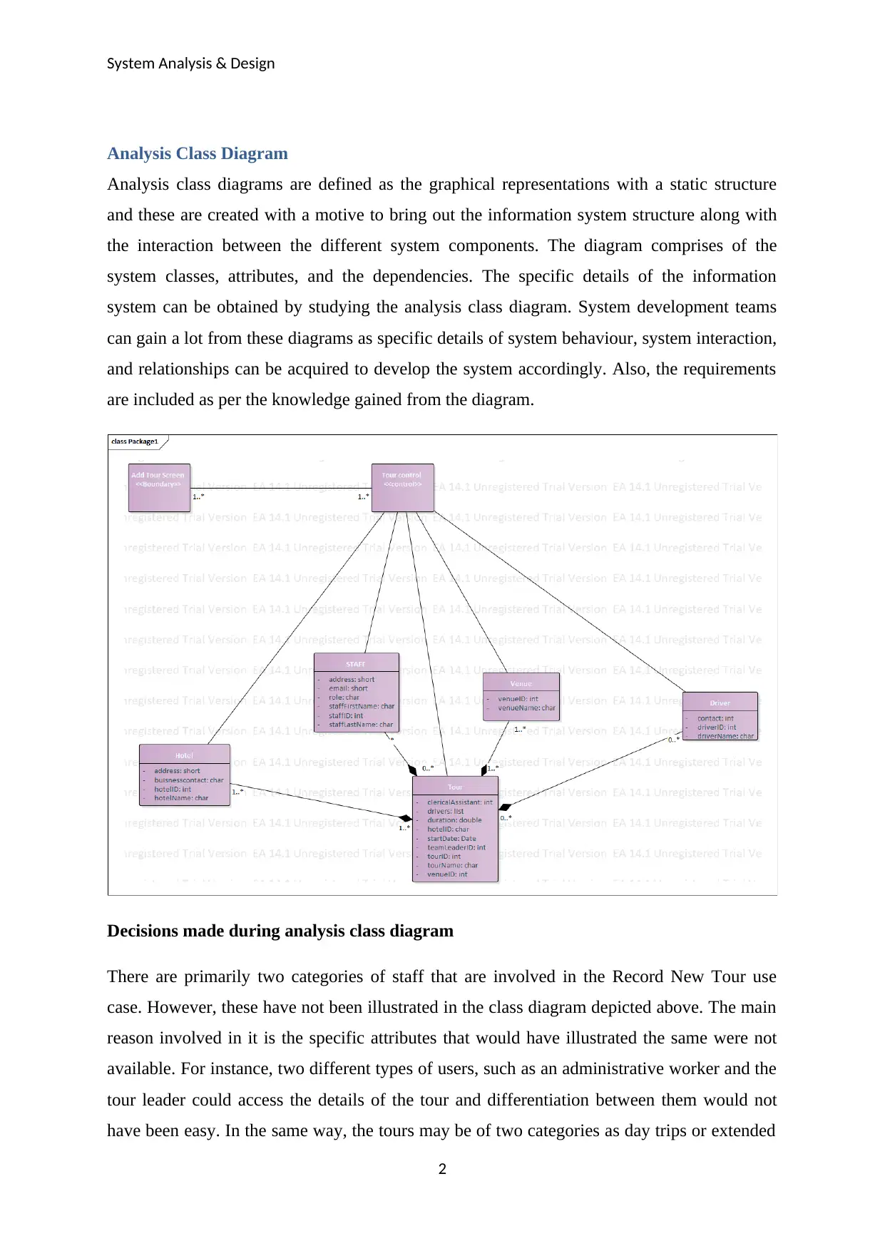
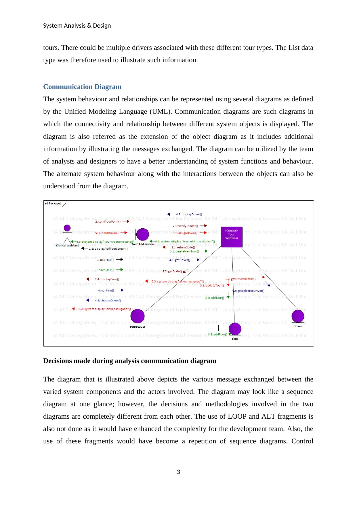
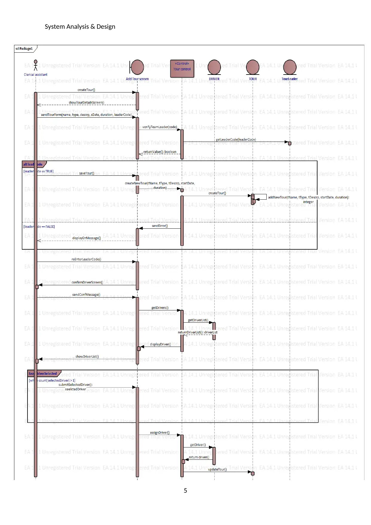
This report provides a comprehensive analysis of system analysis and design, focusing on the application of UML diagrams and CASE tools within the context of the Wide World Tour Management System. It begins with an exploration of analysis class diagrams, detailing their structure and purpose in representing system components and their interactions. The report then delves into communication diagrams, illustrating system behavior and relationships, and sequence diagrams, which model events and processes. It also examines the role and relevance of Computer-Aided Software Engineering (CASE) tools in automating software development activities, particularly within the Wide World Tour Management System. The report highlights the importance of CASE tools in automating the development activities. The report also discusses the role of analysts and designers in utilizing CASE tools and UML to define system requirements, model system behavior, and ensure effective system design. The report also includes how the use of UML diagrams can be done to determine the details of the actors involved along with the information of the actions being performed by each, which can be used in controlling access and permissions.

System Analysis & Design
1/17/2019
1/17/2019
Secure Best Marks with AI Grader
Need help grading? Try our AI Grader for instant feedback on your assignments.

System Analysis & Design
Table of Contents
Analysis Class Diagram.........................................................................................................................2
Communication Diagram......................................................................................................................2
Sequence Diagrams...............................................................................................................................2
CASE Tools...........................................................................................................................................2
Wide World Tour Management System – Relevance of CASE Tools...............................................3
Role of Analyst/Designer – Use of CASE Tools...............................................................................3
Role of Analyst/Designer – Use & Support of UML.........................................................................4
References.............................................................................................................................................5
1

System Analysis & Design
Analysis Class Diagram
Analysis class diagrams are defined as the graphical representations with a static structure
and these are created with a motive to bring out the information system structure along with
the interaction between the different system components. The diagram comprises of the
system classes, attributes, and the dependencies. The specific details of the information
system can be obtained by studying the analysis class diagram. System development teams
can gain a lot from these diagrams as specific details of system behaviour, system interaction,
and relationships can be acquired to develop the system accordingly. Also, the requirements
are included as per the knowledge gained from the diagram.
Decisions made during analysis class diagram
There are primarily two categories of staff that are involved in the Record New Tour use
case. However, these have not been illustrated in the class diagram depicted above. The main
reason involved in it is the specific attributes that would have illustrated the same were not
available. For instance, two different types of users, such as an administrative worker and the
tour leader could access the details of the tour and differentiation between them would not
have been easy. In the same way, the tours may be of two categories as day trips or extended
2

System Analysis & Design
tours. There could be multiple drivers associated with these different tour types. The List data
type was therefore used to illustrate such information.
Communication Diagram
The system behaviour and relationships can be represented using several diagrams as defined
by the Unified Modeling Language (UML). Communication diagrams are such diagrams in
which the connectivity and relationship between different system objects is displayed. The
diagram is also referred as the extension of the object diagram as it includes additional
information by illustrating the messages exchanged. The diagram can be utilized by the team
of analysts and designers to have a better understanding of system functions and behaviour.
The alternate system behaviour along with the interactions between the objects can also be
understood from the diagram.
Decisions made during analysis communication diagram
The diagram that is illustrated above depicts the various message exchanged between the
varied system components and the actors involved. The diagram may look like a sequence
diagram at one glance; however, the decisions and methodologies involved in the two
diagrams are completely different from each other. The use of LOOP and ALT fragments is
also not done as it would have enhanced the complexity for the development team. Also, the
use of these fragments would have become a repetition of sequence diagrams. Control
3
Secure Best Marks with AI Grader
Need help grading? Try our AI Grader for instant feedback on your assignments.

System Analysis & Design
activity involved is the tour controller which will make sure that the leaders and drivers are
adequately allocated to a specific tour.
Sequence Diagrams
The other name for sequence diagrams is event diagrams and these are included for event
modelling for the systems. The details and information of the events are illustrated with the
aid of the horizontal and vertical lines. System processes and objects can be specified using
the vertical lines while the messages exchanged in the system are depicted using the
horizontal lines. There are various phases involved in the software development life cycle and
this diagram is relevant in these phases along with the resources that are involved in these
phases (Misbhauddin and Alshayeb, 2013) .
4

System Analysis & Design
5
5

System Analysis & Design
Decisions made during analysis sequence diagram
The messages and actions that are exchanged between the system actors and the system is
depicted by this diagram. The use case brings out the creation of a new tour and the allocation
of the tour leader to the tour. The availability and validity of the tour leader was necessary
before allocating the leader to the tour. The use of ALT fragment was done to acquire this
information. The understanding of the availability and unavailability of the tour leader was
made clear using the fragment. The analysis of the drivers and their availability was made
using the loop fragment.
CASE Tools
Computer Aided Software Engineering (CASE) is the domain of the tools which are utilized
for designing and implementing the applications. These tools have been developed using
Computer Aided Design (CAD) tools as the base. The automation of the project processes
and operations is carried out with the use of the CASE tools. The simplification of a lot many
software development activities can be easily done using these tools.
Wide World Tour Management System – Relevance of CASE Tools
Wide World Tours made a decision to automate the business operations by implementing an
information system called Tour Management System (TMS) in their architecture. The
primary functionality of the information system would be to manage the tours that are
booked, allocate tour leaders and drivers to the tour, and likewise. The system needs to be
developed and there are a lot many processes that are involved in the development and
implementation process for the information system. The system requirements are a mix of
functional and non-functional aspects and specifications. The use of the CASE tools can be
done to these systems in order to automate the development activities.
One such tool that may be used is the Enterprise Architect tool which may be utilized for
advanced design and analysis of the system. Apart from this, there are also various other tools
that may be utilized. The use of Enterprise Architect and other CASE tools may be done to
develop a list of the system requirements and specifications using different standards, such as
Unified Modeling Language (UML), Business Process Model & Notation (BPMN), and
others. The primary feature of these tools is dynamic model simulation which may be used to
6
Paraphrase This Document
Need a fresh take? Get an instant paraphrase of this document with our AI Paraphraser

System Analysis & Design
gain a better understanding of the system modelling and interactions (Leggate, 2013). The
analysis and verification of the functional and non-functional system requirements can also
be done with the aid of the CASE tools and methods. The background details of the TMS will
be made clear by using the CASE tools which will assist the analysts, designers, developers,
and other resources in their activities. The specific system information will be made clear
with the aid of these tools. Also, the illustration of the relationship matrix, hierarchy
diagrams, etc. will be done using the tool.
Role of Analyst/Designer – Use of CASE Tools
There is an extremely significant role that the System Analysts have in the projects. The
project initiation, planning, and analysis rely heavily on the skills and abilities of the system
analysts.
CASE tools will be used throughout the lifecycle of the software development and the
benefits associated will be provided to the team of analysts as well. The tools will be applied
to identify and utilize the data sources which will enhance the relevance of information and
will reduce the complexities involved in the requirements validation. One of the major issues
that are involved in requirements analysis is data replication. The elimination of all of such
problems will also be done through the involvement of the CASE tools along with the
reduction in complexities and enhancement of efficiencies. The requirements will also be
classified in different categories, such as functional, non-functional, user, and likewise. The
categorization will be simplified with the aid of the tools (Daradkeh, 2017).
The application of these tools will provide block structure which will make it easier to model
the system. There may also be the use of refinement techniques that may be done for
enhancing the system modularity. It is certain that there will be certain alterations that will be
required in the TMS. These changes and alterations will be made using the CASE tools. The
adequate execution of the system analysis phase will also assist the other resources and teams
to easily acquire the information and apply the same for execution of the project activities.
Role of Analyst/Designer – Use & Support of UML
Unified Modeling Language is a standard that is applied in the processes of analysis and
design in the system to bring out the specific details, relationships, and behaviour of the
system. There are various diagrams that have been defined under UML, such as analysis class
diagrams, sequence diagrams, communication diagrams, etc. that may be used by the analysts
to get a hold of the system relationships and dependencies. The system orientation is also
7

System Analysis & Design
enhanced using the UML diagrams and guidelines. For example, communication diagram can
be utilized by the team of analysts and designers to have a better understanding of system
functions and behaviour. The alternate system behaviour along with the interactions between
the objects can also be understood from the diagram (de Marcos, Flores Morador and Javier,
2013).
There are a lot many users that are involved in a particular system and the user control and
permission is carried out by the team of the system analysts. It is the role of the analysts to
determine the permission that shall be granted to the users so that adequate access control is
applied. The use of UML can be done to determine the details of the actors involved along
with the information of the actions being performed by each. The same may be used in
controlling the access and permissions. The sequence and activity diagrams are used to
control the system flow and the details of dependency is acquired using these diagrams
(Turan, 2015). The categorization of the different requirements is also easily done using the
UML diagrams which makes the process of modelling and analysis easy.
8

System Analysis & Design
References
Daradkeh, M. (2017). A preliminary study of user acceptance and adoption of data
visualisation tools for decision support in business organisations. International Journal of
Business Information Systems, 26(3), p.297.
de Marcos, L., Flores Morador, F. and Javier, J. (2013). Modeling with Plato: The Unified
Modeling Language in a Cultural Context. SSRN Electronic Journal.
Leggate, R. (2013). Computer-aided software engineering — turning the corner. Computer-
Aided Engineering Journal, 1(1), p.9.
Misbhauddin, M. and Alshayeb, M. (2013). Extending the UML use case metamodel with
behavioral information to facilitate model analysis and interchange. Software & Systems
Modeling, 14(2), pp.813-838.
Turan, M. (2015). Integrating Software Metrics with UML Class Diagrams. Lecture Notes on
Software Engineering, 3(3), pp.220-224.
9
1 out of 10
Related Documents

Your All-in-One AI-Powered Toolkit for Academic Success.
+13062052269
info@desklib.com
Available 24*7 on WhatsApp / Email
Unlock your academic potential
© 2024 | Zucol Services PVT LTD | All rights reserved.