ATMC ICT700 Systems Analysis and Design Report for OZES Company

Verified

Added on  2023/03/30

|15
|2213
|386
Report
AI Summary
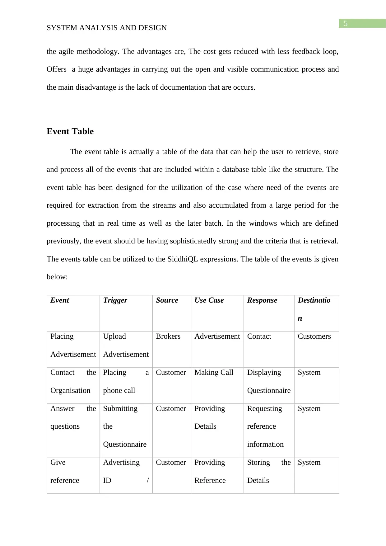
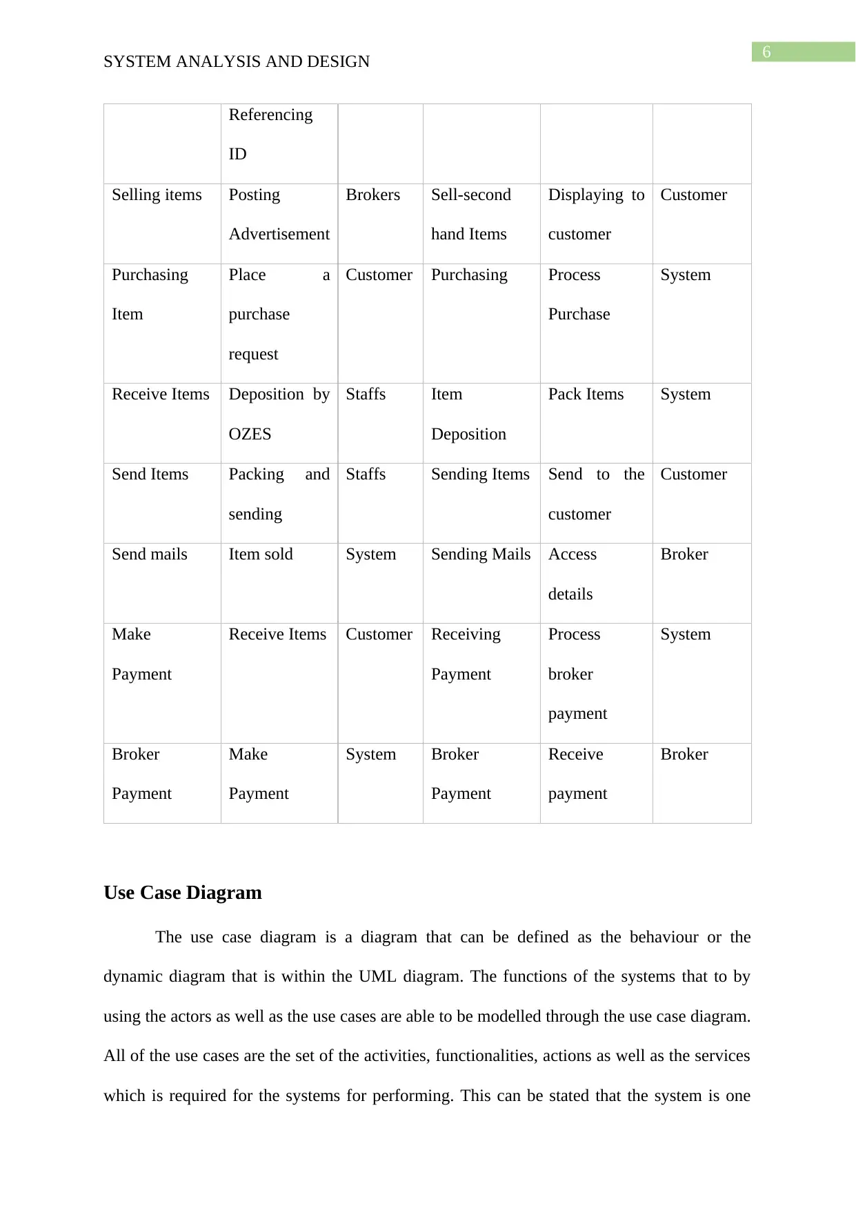
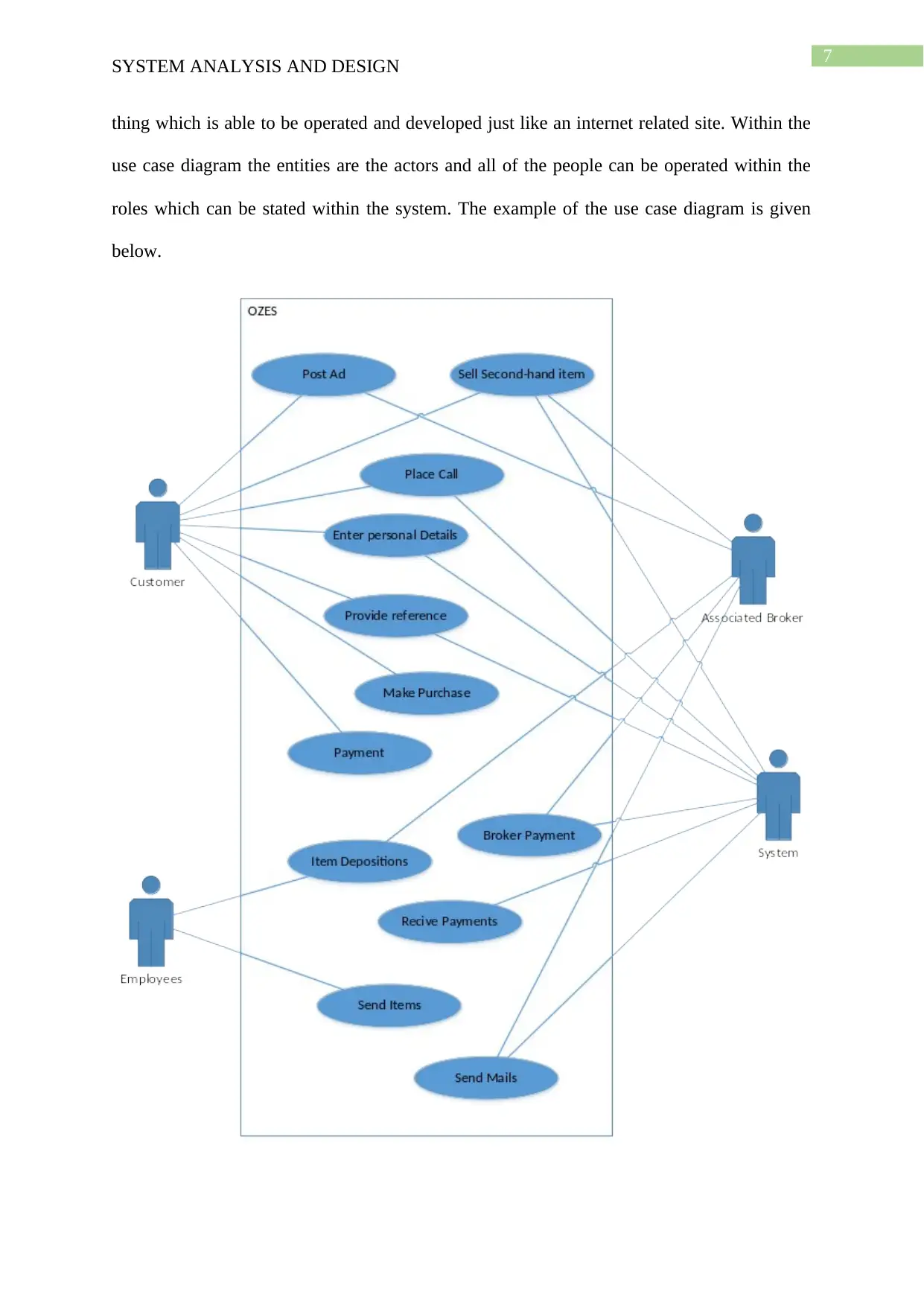
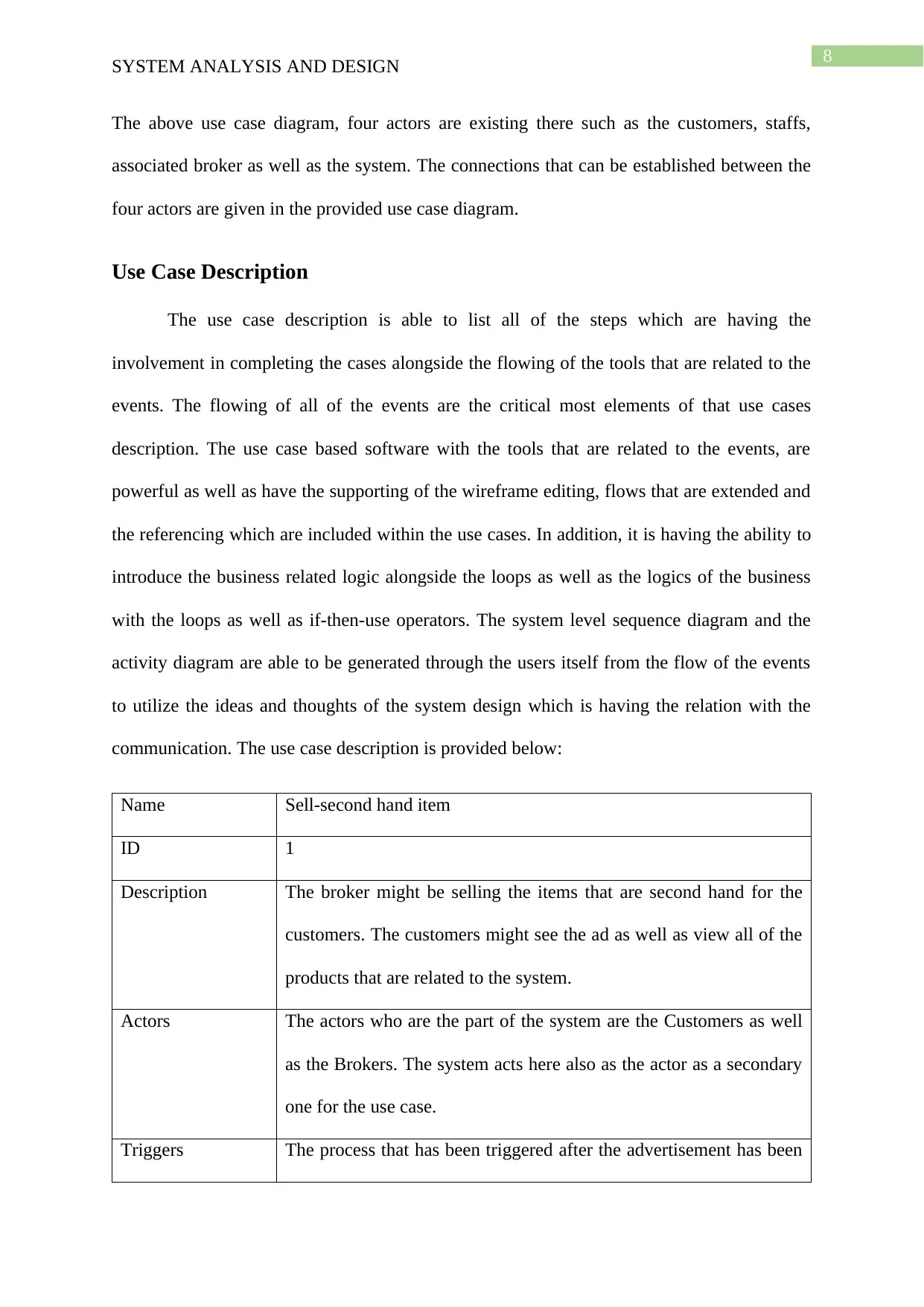
This report presents a system analysis and design for the OZES Company, focusing on the application of various methodologies and tools. The methodology section details Extreme Programming (XP), Scrum, and Feature Driven Development (FDD), outlining their advantages and disadvantages. Event tables, use case diagrams, and use case descriptions are provided to illustrate system functionalities and interactions. Furthermore, the report includes domain model and design class diagrams to visualize the system's structure and components. A memo to the CEO of OZES addresses the adoption of User-Centred Design (UCD) and Human-Computer Interaction (HCI) to improve customer relationship management. The report emphasizes the importance of UCD in meeting user requirements and structuring effective HCI within the organization. The use case based software with the tools that are related to the events, are powerful as well as have the supporting of the wireframe editing, flows that are extended and the referencing which are included within the use cases. In addition, it is having the ability to introduce the business related logic alongside the loops as well as the logics of the business with the loops as well as if-then-use operators. The report concludes with a discussion on how these elements contribute to a well-designed and user-focused system for OZES.
Document Page
Running head: SYSTEM ANALYSIS AND DESIGN
System Analysis and Design
Name of the Student:
Name of the University:
Author Note
tabler-icon-diamond-filled.svg

Paraphrase This Document

Need a fresh take? Get an instant paraphrase of this document with our AI Paraphraser
Document Page
1
SYSTEM ANALYSIS AND DESIGN
Executive summary:
The purpose of this paper is to provide a methodology and memo for the OZES Company.
Document Page
2
SYSTEM ANALYSIS AND DESIGN
Table of Contents
Methodology:.............................................................................................................................4
Extreme programming (XP):......................................................................................................4
Event Table................................................................................................................................5
Use Case Diagram......................................................................................................................7
Use Case Description.................................................................................................................9
Domain Model Class Diagram.................................................................................................10
Design Class Diagram..............................................................................................................11
Bibliography.............................................................................................................................13
Document Page
3
SYSTEM ANALYSIS AND DESIGN
Methodology:
The main idea that is associated with the development of agile methodology is to determine
the several convoluted methods that can be sued for the purpose of pervading the software
development process. The method mainly focuses on determining the satisfaction that is
gained from the customers, focuses on developing the project based on the agile
methodology, and follows different project management criteria for generating the project.
Extreme programming (XP):
This is mainly described as one of the major factors for determining the project process. This
is one of the foremost agile technologies that focus on describing the effective high degree
participation along with different parties. This involves the developers and customers
effectively for the purpose of having effective software exchange. The developer also
includes generating the upgraded software along with the performance that will be able to
bring new innovation for the customers associated with the products. Apart from this the
customers also focuses on development of the process by focusing on the development
features that are offered with the software product. With the help of feedbacks it becomes
easy to manage the customer development process and also helps in understanding the basic
needs associated with each customers for better development process. The methodology
mainly focuses on five values that are the communication, respect, simplicity, feedback and
courage. These values will have a better control over the OZES for countering the issues
within the current business scenario. The methodologies have certain advantages and
disadvantages that are described below:
Advantages
The major advantages with these methodologies are as follows:
tabler-icon-diamond-filled.svg

Paraphrase This Document

Need a fresh take? Get an instant paraphrase of this document with our AI Paraphraser
Document Page
4
SYSTEM ANALYSIS AND DESIGN
ï‚· The processing time does not get wasted and provides a faster working environment
as compared to the other deployment processes.
ï‚· The cost gets reduced with less feedback loop
ï‚· Offers a huge advantages in carrying out the open and visible communication process
ï‚· Eliminates the bugs and reduces the chances of failure
Disadvantages
ï‚· It becomes difficult to manage the constant changes
ï‚· Lack of documentation occurs
ï‚· It becomes difficult to locate when the customer is away from the XP programs
Scrum:
This methodology of the agile comprises with the development that is the complicated most.
Such as the extreme programming the owner of an item must collaborate with the IT as well
as the development tem for the harness that is collective. The developer also includes
generating the upgraded software along with the performance that will be able to bring new
innovation for the customers associated with the products. Apart from this the customers also
focuses on development of the process by focusing on the development features that are
offered with the software product. The main advantage of this is Effective use of cost as well
as the time is ensured here. The disadvantage is the Lack of a perfect end date sometimes for
creating the scope creep.
Feature driven development:
The method that has been discusses as the FDD methodology turns this model in the
various builds at the iteration that are fortnight. The method mainly focuses on determining
the satisfaction that is gained from the customers, focuses on developing the project based on
Document Page
5
SYSTEM ANALYSIS AND DESIGN
the agile methodology. The advantages are, The cost gets reduced with less feedback loop,
Offers a huge advantages in carrying out the open and visible communication process and
the main disadvantage is the lack of documentation that are occurs.
Event Table
The event table is actually a table of the data that can help the user to retrieve, store
and process all of the events that are included within a database table like the structure. The
event table has been designed for the utilization of the case where need of the events are
required for extraction from the streams and also accumulated from a large period for the
processing that in real time as well as the later batch. In the windows which are defined
previously, the event should be having sophisticatedly strong and the criteria that is retrieval.
The events table can be utilized to the SiddhiQL expressions. The table of the events is given
below:
Event Trigger Source Use Case Response Destinatio
n
Placing
Advertisement
Upload
Advertisement
Brokers Advertisement Contact Customers
Contact the
Organisation
Placing a
phone call
Customer Making Call Displaying
Questionnaire
System
Answer the
questions
Submitting
the
Questionnaire
Customer Providing
Details
Requesting
reference
information
System
Give
reference
Advertising
ID /
Customer Providing
Reference
Storing the
Details
System
Document Page
6
SYSTEM ANALYSIS AND DESIGN
Referencing
ID
Selling items Posting
Advertisement
Brokers Sell-second
hand Items
Displaying to
customer
Customer
Purchasing
Item
Place a
purchase
request
Customer Purchasing Process
Purchase
System
Receive Items Deposition by
OZES
Staffs Item
Deposition
Pack Items System
Send Items Packing and
sending
Staffs Sending Items Send to the
customer
Customer
Send mails Item sold System Sending Mails Access
details
Broker
Make
Payment
Receive Items Customer Receiving
Payment
Process
broker
payment
System
Broker
Payment
Make
Payment
System Broker
Payment
Receive
payment
Broker
Use Case Diagram
The use case diagram is a diagram that can be defined as the behaviour or the
dynamic diagram that is within the UML diagram. The functions of the systems that to by
using the actors as well as the use cases are able to be modelled through the use case diagram.
All of the use cases are the set of the activities, functionalities, actions as well as the services
which is required for the systems for performing. This can be stated that the system is one
tabler-icon-diamond-filled.svg

Paraphrase This Document

Need a fresh take? Get an instant paraphrase of this document with our AI Paraphraser
Document Page
7
SYSTEM ANALYSIS AND DESIGN
thing which is able to be operated and developed just like an internet related site. Within the
use case diagram the entities are the actors and all of the people can be operated within the
roles which can be stated within the system. The example of the use case diagram is given
below.
Document Page
8
SYSTEM ANALYSIS AND DESIGN
The above use case diagram, four actors are existing there such as the customers, staffs,
associated broker as well as the system. The connections that can be established between the
four actors are given in the provided use case diagram.
Use Case Description
The use case description is able to list all of the steps which are having the
involvement in completing the cases alongside the flowing of the tools that are related to the
events. The flowing of all of the events are the critical most elements of that use cases
description. The use case based software with the tools that are related to the events, are
powerful as well as have the supporting of the wireframe editing, flows that are extended and
the referencing which are included within the use cases. In addition, it is having the ability to
introduce the business related logic alongside the loops as well as the logics of the business
with the loops as well as if-then-use operators. The system level sequence diagram and the
activity diagram are able to be generated through the users itself from the flow of the events
to utilize the ideas and thoughts of the system design which is having the relation with the
communication. The use case description is provided below:
Name Sell-second hand item
ID 1
Description The broker might be selling the items that are second hand for the
customers. The customers might see the ad as well as view all of the
products that are related to the system.
Actors The actors who are the part of the system are the Customers as well
as the Brokers. The system acts here also as the actor as a secondary
one for the use case.
Triggers The process that has been triggered after the advertisement has been
Document Page
9
SYSTEM ANALYSIS AND DESIGN
posted by the broker.
Pre-condition Advertisement
Post-condition Make Purchase
Flow of process Actor System
1. Sending advertisement
2. Sell Second-hand item
3. Making Purchase
1. Posting Advertisement
2. Displaying item to the
customer
3. Selling Item
Exceptions Exceptions are able to take place whether the advertisement have not
reach out to the consumer...
Domain Model Class Diagram
The domain model class diagram is one of the most conceptual of such domain in the
software engineering. The domain model class diagram is one such system which is having a
relation with the abstractions that have the ability for describing all of the aspects of the
knowledge sphere which has been selected. For getting the solution of the issues as well as
the problems the domain model can be utilized. The domain model class diagram is the
representative of all of the concepts which have a meaning that is related to the real world
problems as well as the pertinent for that domain that are needed for being implemented
within the software. The domain class diagram is given below.
tabler-icon-diamond-filled.svg

Paraphrase This Document

Need a fresh take? Get an instant paraphrase of this document with our AI Paraphraser
Document Page
10
SYSTEM ANALYSIS AND DESIGN
Design Class Diagram
The completion of the diagram that known as the interaction for the use cases
realisation, the possibility is there for the identification of the specifications of the software
classes which are able to participate in the solution for the software. The design class diagram
have been generally created with the interaction diagrams. The example of the design class
diagram is as following.
Document Page
11
SYSTEM ANALYSIS AND DESIGN
In this diagram the phone number, broker id, payment and date has been taken as integer and
on the other side the address, broker name and the detail are defined as the string.
Memo
To: CEO, OZES
From: Enterprise Software Developer
CC: CEO, Enterprise Software Developer
Date: August 30, 2024
Re: Evaluation of UCD and HCI
Adopting a User Centred Design (UCD) approach
Background:
chevron_up_icon
1 out of 15
circle_padding
hide_on_mobile
zoom_out_icon
[object Object]