System Analysis and Design Report: Semester 2 System Design Project

Verified

Added on  2023/04/25

|14
|1643
|170
Report
AI Summary
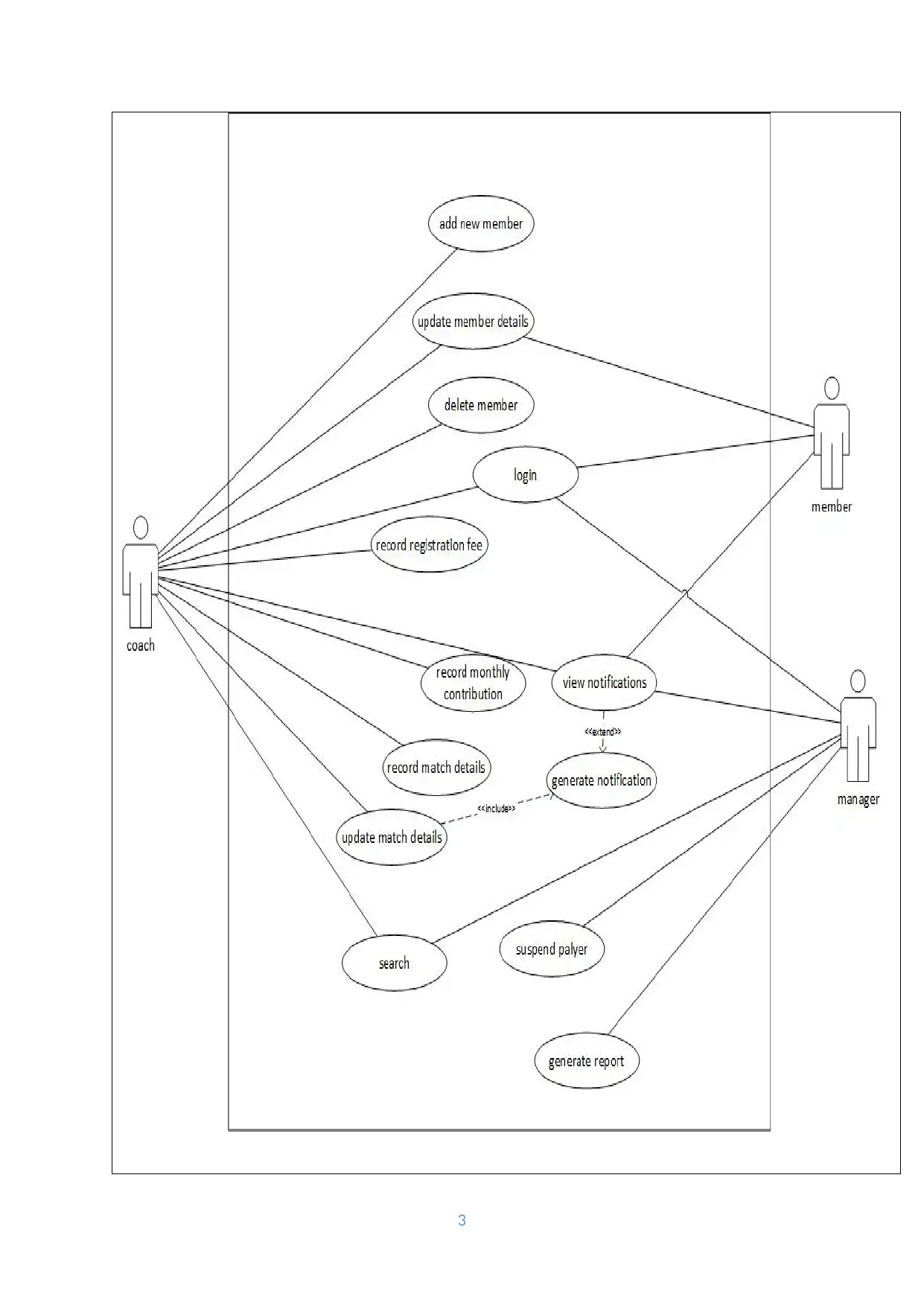
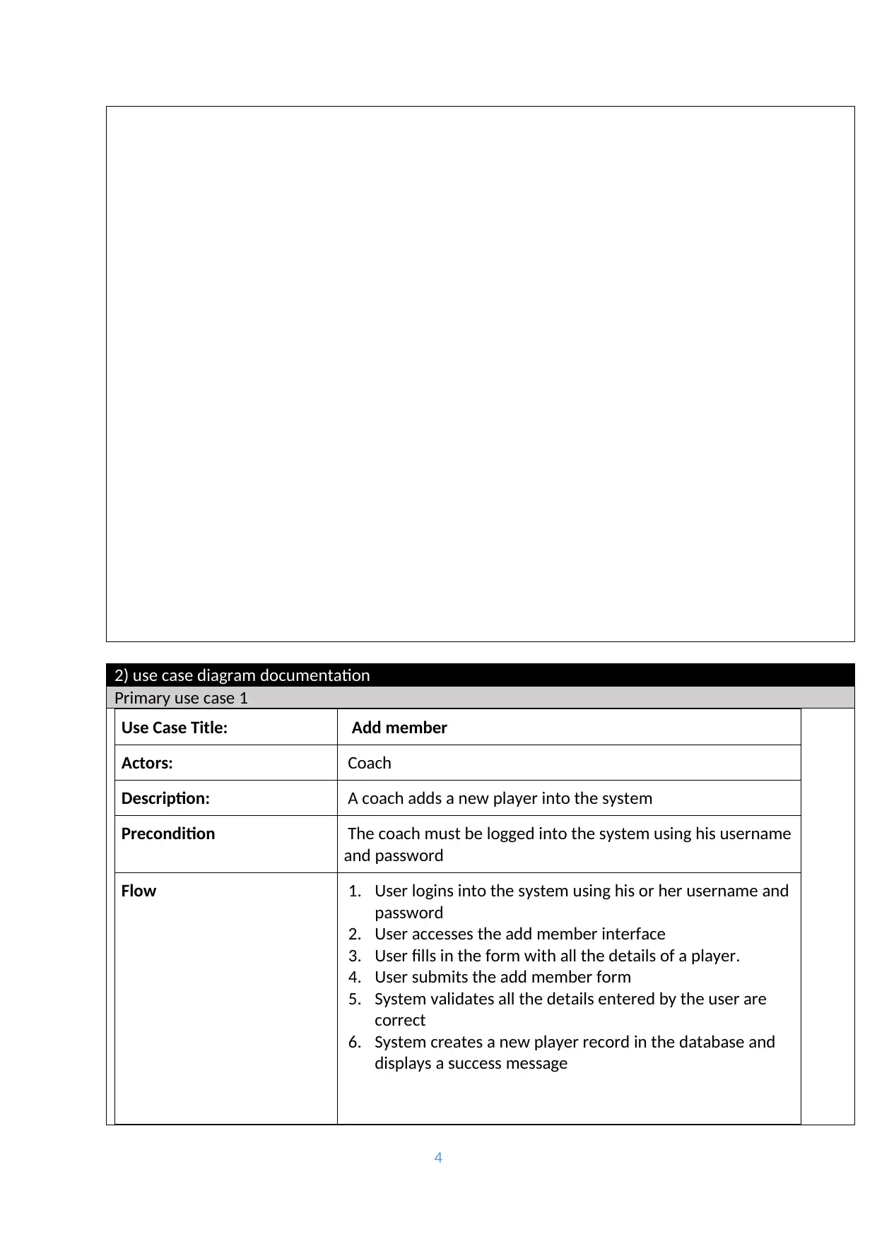
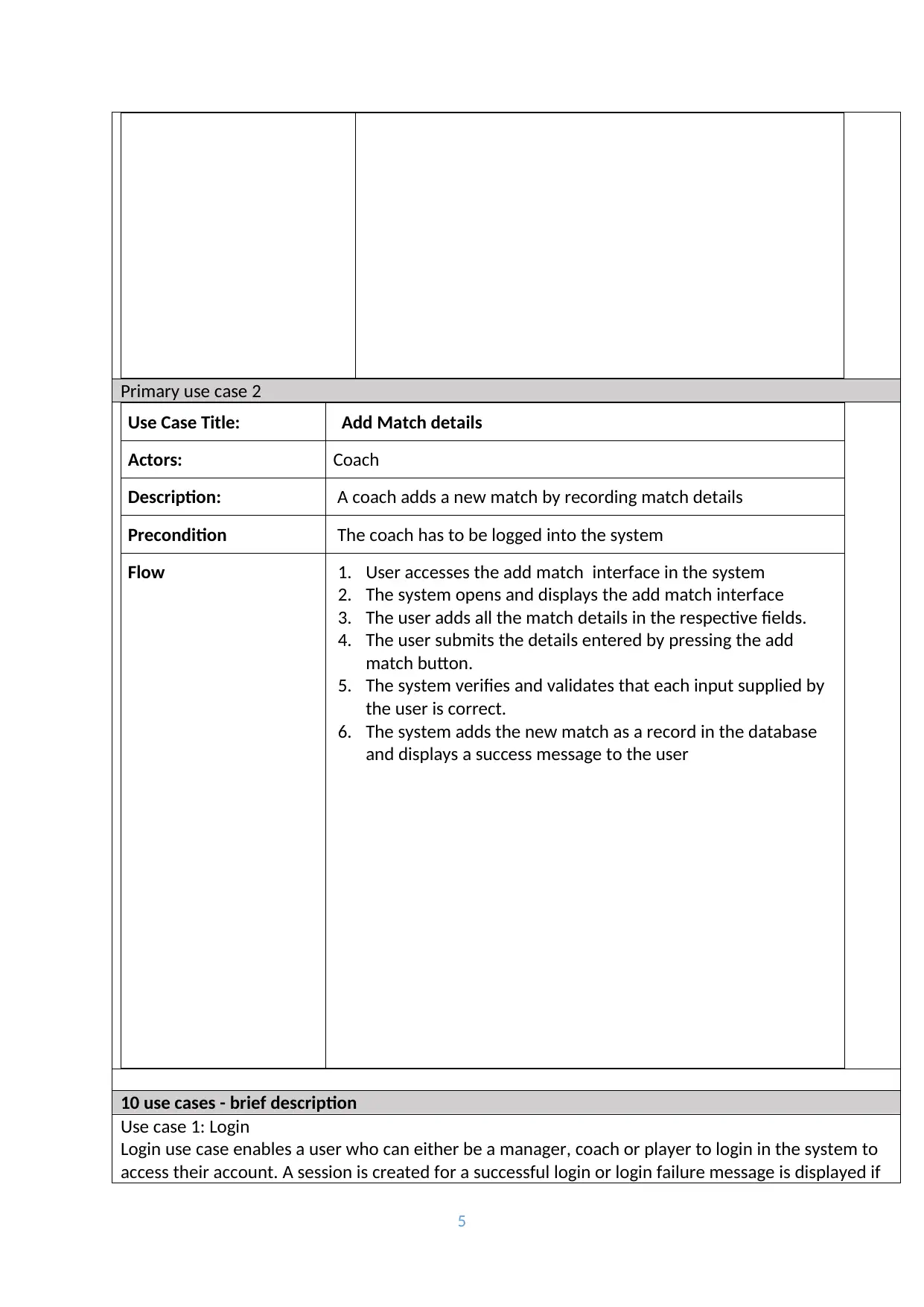
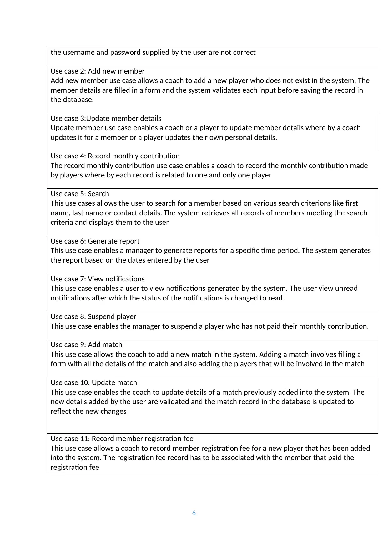
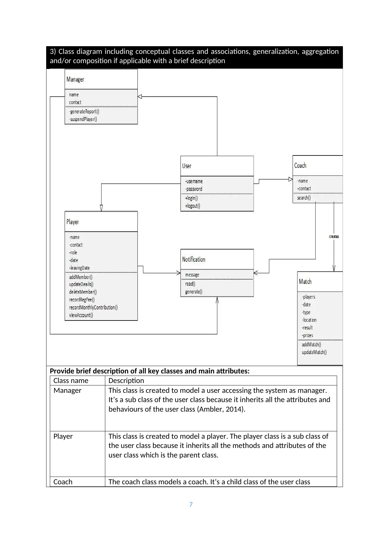
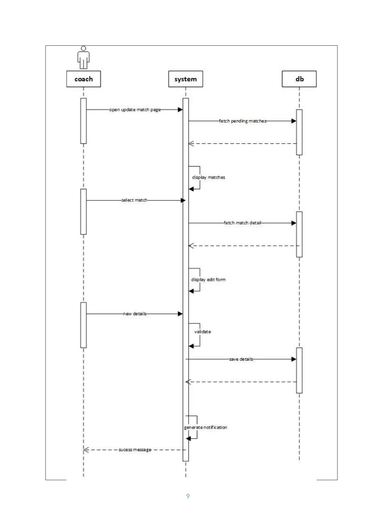
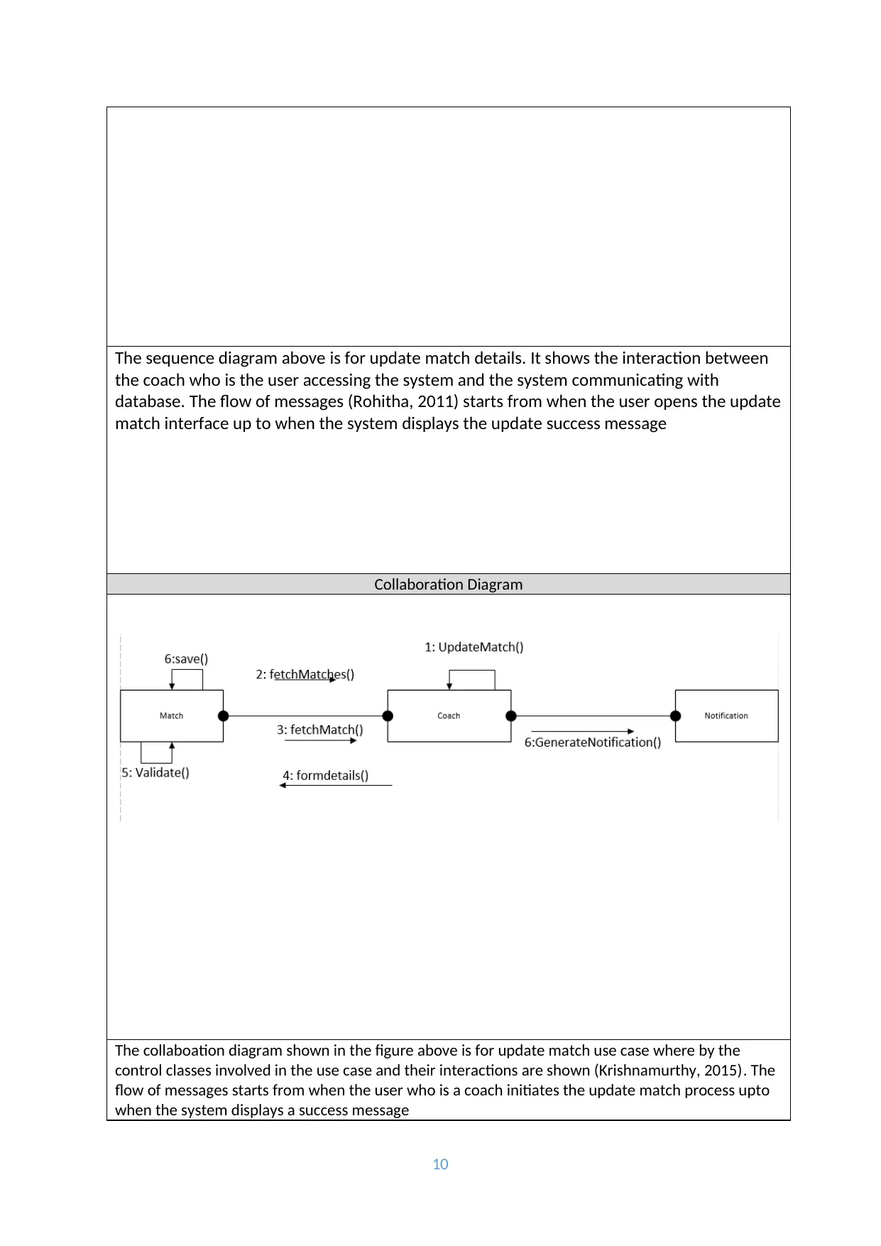
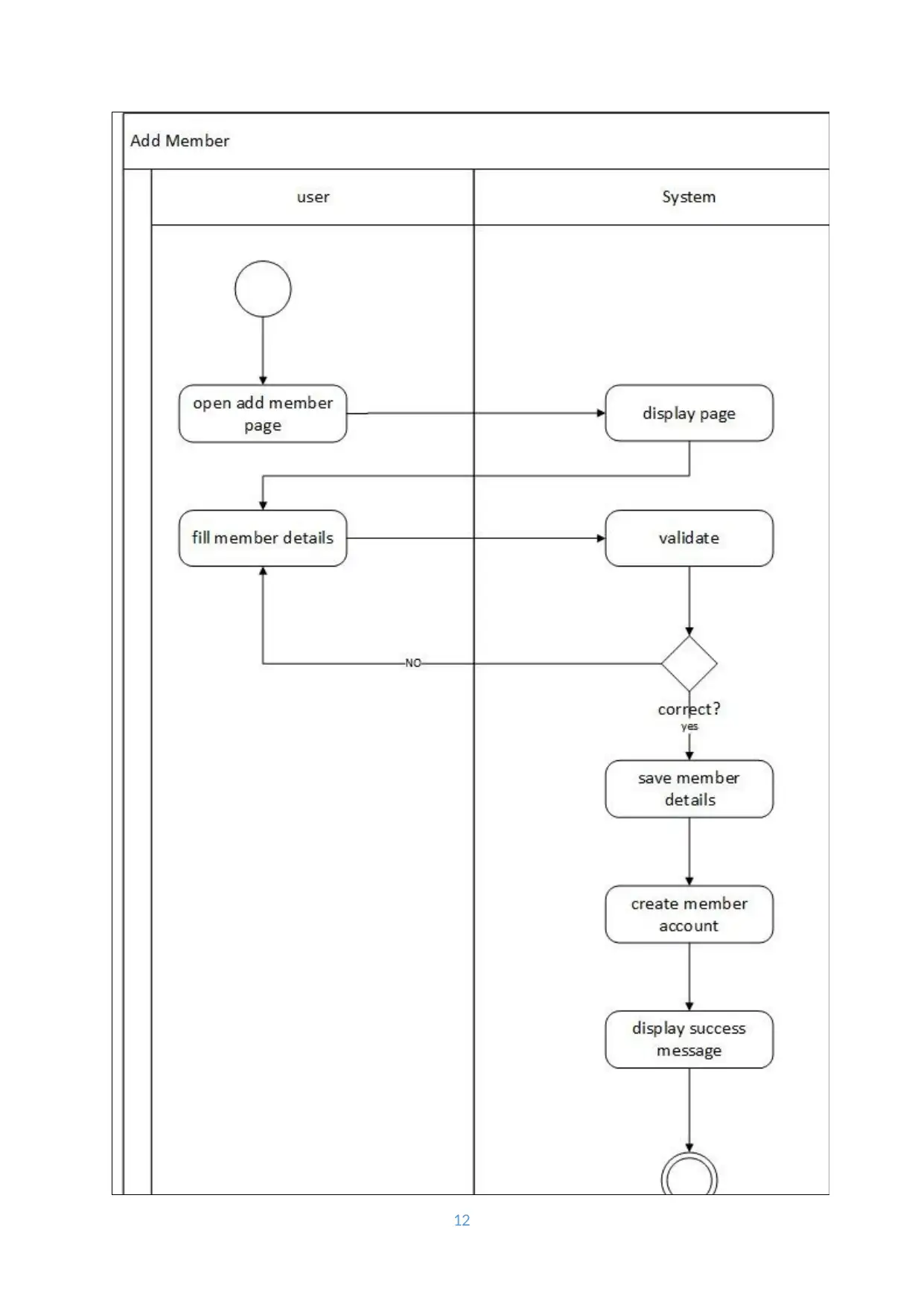
This report provides a comprehensive analysis and design of a system, detailing the functional requirements and utilizing UML diagrams for representation. It includes a use case diagram outlining system functionalities such as user login, member management, match management, and report generation. Detailed use case descriptions are provided for adding a member and adding match details, followed by brief descriptions of ten use cases including login, adding/updating member details, recording contributions, search, report generation, and managing matches and notifications. A class diagram illustrates the system's static structure with key classes like Manager, Player, Coach, User, Notification, and Match, along with their attributes and relationships. Furthermore, the report includes interaction diagrams, specifically sequence and collaboration diagrams for updating match details, showing the flow of messages between the user, system, and database. A flowchart/activity diagram visually represents the logic flow for adding a new member. The appendix summarizes the UML diagrams used and their purpose, referencing relevant literature for system modeling techniques. Desklib provides this and many other solved assignments for students.
tabler-icon-diamond-filled.svg

Contribute Materials

Your contribution can guide someone’s learning journey. Share your documents today.
Document Page
System Analysis and Design Solution Template
Academic year and term: 2017/2018 – Semester-2, Year 1
Module title: System Analysis and Design
Module code: QAC020C154S
Module Convener: Hassan Baajour
Module Tutor: PLEASE ENTER YOUR TUTOR NAME HERE
Student Id: PLEASE ENTER YOUR STUDENT ID HERE
Deadline: 16-07-18 (no later than 2pm)
Coursework 1: System Design
1
tabler-icon-diamond-filled.svg

Secure Best Marks with AI Grader

Need help grading? Try our AI Grader for instant feedback on your assignments.
Document Page
Use case diagram
1.1 Functional requirements
Users should be able to login into the system.
A user should be able to add a new member not existing in the system.
A user should be able to update details of a member that has already been added in the
system.
A user should be able to delete details of a member added in the system.
A user should be able to record a member’s registration fee.
A user should be able to record member’s monthly contribution
A user should be able to suspend a player who does not paid monthly contribution.
A user should be able to dismiss a player who has not paid monthly subscriptions for three
consecutive months.
A user of the system should be able to add a match and record its details including the players
that played in that match.
A user should be able to update match details that has already been added to the system.
A user should be able to search for a member using the system.
A user of the system should be able to generate different type of reports.
A user should be able to view notifications generated by the system.
1.2 use case diagram
2
Document Page
3
Document Page
2) use case diagram documentation
Primary use case 1
Use Case Title: Add member
Actors: Coach
Description: A coach adds a new player into the system
Precondition The coach must be logged into the system using his username
and password
Flow 1. User logins into the system using his or her username and
password
2. User accesses the add member interface
3. User fills in the form with all the details of a player.
4. User submits the add member form
5. System validates all the details entered by the user are
correct
6. System creates a new player record in the database and
displays a success message
4
tabler-icon-diamond-filled.svg

Secure Best Marks with AI Grader

Need help grading? Try our AI Grader for instant feedback on your assignments.
Document Page
Primary use case 2
Use Case Title: Add Match details
Actors: Coach
Description: A coach adds a new match by recording match details
Precondition The coach has to be logged into the system
Flow 1. User accesses the add match interface in the system
2. The system opens and displays the add match interface
3. The user adds all the match details in the respective fields.
4. The user submits the details entered by pressing the add
match button.
5. The system verifies and validates that each input supplied by
the user is correct.
6. The system adds the new match as a record in the database
and displays a success message to the user
10 use cases - brief description
Use case 1: Login
Login use case enables a user who can either be a manager, coach or player to login in the system to
access their account. A session is created for a successful login or login failure message is displayed if
5
Document Page
the username and password supplied by the user are not correct
Use case 2: Add new member
Add new member use case allows a coach to add a new player who does not exist in the system. The
member details are filled in a form and the system validates each input before saving the record in
the database.
Use case 3:Update member details
Update member use case enables a coach or a player to update member details where by a coach
updates it for a member or a player updates their own personal details.
Use case 4: Record monthly contribution
The record monthly contribution use case enables a coach to record the monthly contribution made
by players where by each record is related to one and only one player
Use case 5: Search
This use cases allows the user to search for a member based on various search criterions like first
name, last name or contact details. The system retrieves all records of members meeting the search
criteria and displays them to the user
Use case 6: Generate report
This use case enables a manager to generate reports for a specific time period. The system generates
the report based on the dates entered by the user
Use case 7: View notifications
This use case enables a user to view notifications generated by the system. The user view unread
notifications after which the status of the notifications is changed to read.
Use case 8: Suspend player
This use case enables the manager to suspend a player who has not paid their monthly contribution.
Use case 9: Add match
This use case allows the coach to add a new match in the system. Adding a match involves filling a
form with all the details of the match and also adding the players that will be involved in the match
Use case 10: Update match
This use case enables the coach to update details of a match previously added into the system. The
new details added by the user are validated and the match record in the database is updated to
reflect the new changes
Use case 11: Record member registration fee
This use case allows a coach to record member registration fee for a new player that has been added
into the system. The registration fee record has to be associated with the member that paid the
registration fee
6
Document Page
3) Class diagram including conceptual classes and associations, generalization, aggregation
and/or composition if applicable with a brief description
Provide brief description of all key classes and main attributes:
Class name Description
Manager This class is created to model a user accessing the system as manager.
It’s a sub class of the user class because it inherits all the attributes and
behaviours of the user class (Ambler, 2014).
Player This class is created to model a player. The player class is a sub class of
the user class because it inherits all the methods and attributes of the
user class which is the parent class.
Coach The coach class models a coach. It’s a child class of the user class
7
tabler-icon-diamond-filled.svg

Paraphrase This Document

Need a fresh take? Get an instant paraphrase of this document with our AI Paraphraser
Document Page
because it inherits all the attributes and behaviours of the user class.
User This class models a system user who can either a player, coach or
manager. It’s the parent class of the manager, player and coach classes.
Notification This class models a notification generated by the system. The attribute
of this class is the message attribute of type string
Match The match class models a match played by players. The match
attributes are players which is an array list consisting of the players
playing the match, date, location, type, results and prizes
4) Interaction diagram
Sequence Diagram
Update match sequence diagram
8
Document Page
9
Document Page
The sequence diagram above is for update match details. It shows the interaction between
the coach who is the user accessing the system and the system communicating with
database. The flow of messages (Rohitha, 2011) starts from when the user opens the update
match interface up to when the system displays the update success message
Collaboration Diagram
The collaboation diagram shown in the figure above is for update match use case where by the
control classes involved in the use case and their interactions are shown (Krishnamurthy, 2015). The
flow of messages starts from when the user who is a coach initiates the update match process upto
when the system displays a success message
10
tabler-icon-diamond-filled.svg

Secure Best Marks with AI Grader

Need help grading? Try our AI Grader for instant feedback on your assignments.
Document Page
Flowchart/Activity Diagram
11
Document Page
12
Document Page
The flow chart above shows the logic flow for add new member primary use case. The flow of logic is
between the system and the user. The user starts the process when he or she opens the add
member page upto when the system displays a success message to the user
Appendix
To model the proposed system using UML different diagras have been used. The use case diagram is
based on the functional requirements of the system. Based on the use case diagrams, detailed use
case descriptions are derived for the primary use cases of the system. The detailed use case
descriptions are then used to model the static and behavioral structure of the system using a class
diagram. Interaction diagrams including sequence diagram and collabroation diagram are used to
show a more details of the behavioral structure of the system
References
Ambler, S.W., 2014. UML 2 Class Diagrams: An Agile Introduction. Agile Modelling. Available at:
http://www.agilemodeling.com/artifacts/classDiagram.htm [Accessed March 18, 2019].
Krishnamurthy, G.A., 2015. CASE Tools. umsl. Available at:
http://www.umsl.edu/~sauterv/analysis/F08papers/View.html [Accessed March 18, 2019].
Rohitha, 2011. The Basics & the Purpose of Sequence Diagrams ~ Part 1. creately blog. Available at:
http://creately.com/blog/diagrams/the-basics-the-purpose-of-sequence-diagrams-part-1/ [Accessed
March 18, 2019].
13
tabler-icon-diamond-filled.svg

Paraphrase This Document

Need a fresh take? Get an instant paraphrase of this document with our AI Paraphraser
Document Page
14
chevron_up_icon
1 out of 14
circle_padding
hide_on_mobile
zoom_out_icon
logo.png

Your All-in-One AI-Powered Toolkit for Academic Success.

Available 24*7 on WhatsApp / Email

[object Object]