IMAT5205 - System Analysis and Design: Modeling Report 2018-19
VerifiedAdded on 2023/04/20
|13
|2037
|377
Report
AI Summary
This report provides a system analysis and design overview, focusing on UML diagrams and CASE tools. It includes an analysis class diagram defining the structure and relationships between classes within a system, a communication diagram illustrating object interactions and message flows, and a sequence diagram showing the timeline of message exchanges between classes. The report also discusses the role and effectiveness of Computer-Aided Software Engineering (CASE) technologies in software development, particularly in the tourism industry, highlighting their benefits in increasing productivity, reducing maintenance costs, and improving project management. The document emphasizes the use of CASE tools for developing maintainable, high-quality applications and enhancing the overall software development process. Desklib provides access to this document and many more resources for students.

Running head: SYSTEM ANALYSIS AND DESIGN
System Analysis and Design
Name of the Student
Name of the University
Author Note
System Analysis and Design
Name of the Student
Name of the University
Author Note
Paraphrase This Document
Need a fresh take? Get an instant paraphrase of this document with our AI Paraphraser
1System Analysis and Design
Table of Contents
Analysis Class Diagram.............................................................................................................2
a) Class Diagram Definition................................................................................................2
b) Class Diagram.................................................................................................................2
c) Summary.........................................................................................................................2
Communication diagram:...........................................................................................................3
a) Definition........................................................................................................................3
b) Diagram...........................................................................................................................3
c) Summary.........................................................................................................................4
Sequence Diagram.....................................................................................................................5
a) Definition........................................................................................................................5
Diagram..................................................................................................................................5
b) Summary.........................................................................................................................5
Task 3:........................................................................................................................................7
References:...............................................................................................................................11
2System Analysis and Design
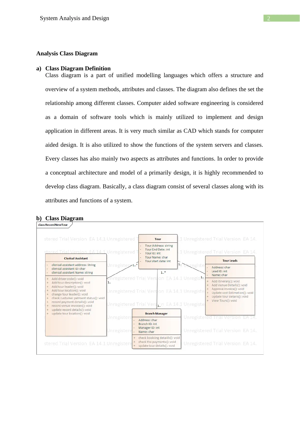
Analysis Class Diagram
a) Class Diagram Definition
Class diagram is a part of unified modelling languages which offers a structure and
overview of a system methods, attributes and classes. The diagram also defines the set the
relationship among different classes. Computer aided software engineering is considered
as a domain of software tools which is mainly utilized to implement and design
application in different areas. It is very much similar as CAD which stands for computer
aided design. It is also utilized to show the functions of the system servers and classes.
Every classes has also mainly two aspects as attributes and functions. In order to provide
a conceptual architecture and model of a primarily design, it is highly recommended to
develop class diagram. Basically, a class diagram consist of several classes along with its
attributes and functions of a system.
b) Class Diagram
⊘ This is a preview!⊘
Do you want full access?
Subscribe today to unlock all pages.
Trusted by 1+ million students worldwide
3System Analysis and Design
c) Summary
The above diagram shows the classes of the TMS system. In this diagram three classes are
identified as Clerical assistant, tour leaders along with branch manager and tour. These are
the main three actors responsible for record a tour. The initiation process can be start by both
clerical assistant and branch manager as they both could add tour and other tour details. The
clerical assistant has several attributes as clerical assistant name, clerical assistant ID, clerical
assistant address. Additionally, the class has several functions like add driver code, add tour
description, add tour leader, add tour location, update tour leader, Check customer payment
details, record payment details, record venue invoices, update record details and update tour
location. The clerical assistant class forms one to many relation with the class tour which also
has one to one relation with the tour leads. The branch class has a one to many relation with
the tour class well.
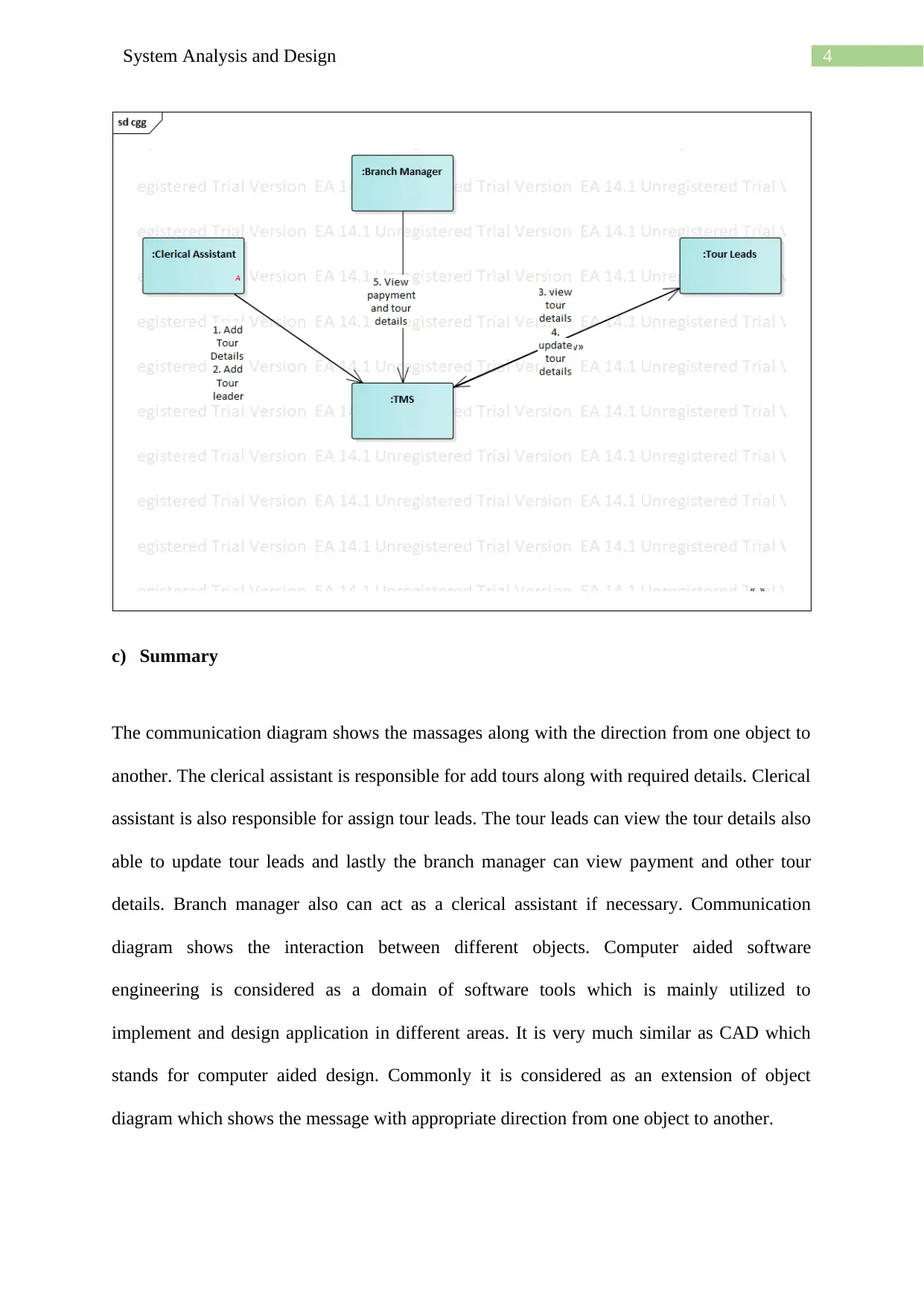
Communication diagram:
a) Definition
Communication diagram shows the interaction between different objects. Commonly it is
considered as an extension of object diagram which shows message with appropriate
direction from one object to another. It has been helping in the developemnt of the system in
appositive manner that [provide high efficiency rate to the output. It also model alternative
scenarios within the operations that associates with different collaboration of different
objects. It also support the identification of objects, and their attributes and operations that
participate in use cases.
b) Diagram
c) Summary
The above diagram shows the classes of the TMS system. In this diagram three classes are
identified as Clerical assistant, tour leaders along with branch manager and tour. These are
the main three actors responsible for record a tour. The initiation process can be start by both
clerical assistant and branch manager as they both could add tour and other tour details. The
clerical assistant has several attributes as clerical assistant name, clerical assistant ID, clerical
assistant address. Additionally, the class has several functions like add driver code, add tour
description, add tour leader, add tour location, update tour leader, Check customer payment
details, record payment details, record venue invoices, update record details and update tour
location. The clerical assistant class forms one to many relation with the class tour which also
has one to one relation with the tour leads. The branch class has a one to many relation with
the tour class well.
Communication diagram:
a) Definition
Communication diagram shows the interaction between different objects. Commonly it is
considered as an extension of object diagram which shows message with appropriate
direction from one object to another. It has been helping in the developemnt of the system in
appositive manner that [provide high efficiency rate to the output. It also model alternative
scenarios within the operations that associates with different collaboration of different
objects. It also support the identification of objects, and their attributes and operations that
participate in use cases.
b) Diagram
Paraphrase This Document
Need a fresh take? Get an instant paraphrase of this document with our AI Paraphraser
4System Analysis and Design
c) Summary
The communication diagram shows the massages along with the direction from one object to
another. The clerical assistant is responsible for add tours along with required details. Clerical
assistant is also responsible for assign tour leads. The tour leads can view the tour details also
able to update tour leads and lastly the branch manager can view payment and other tour
details. Branch manager also can act as a clerical assistant if necessary. Communication
diagram shows the interaction between different objects. Computer aided software
engineering is considered as a domain of software tools which is mainly utilized to
implement and design application in different areas. It is very much similar as CAD which
stands for computer aided design. Commonly it is considered as an extension of object
diagram which shows the message with appropriate direction from one object to another.
5System Analysis and Design
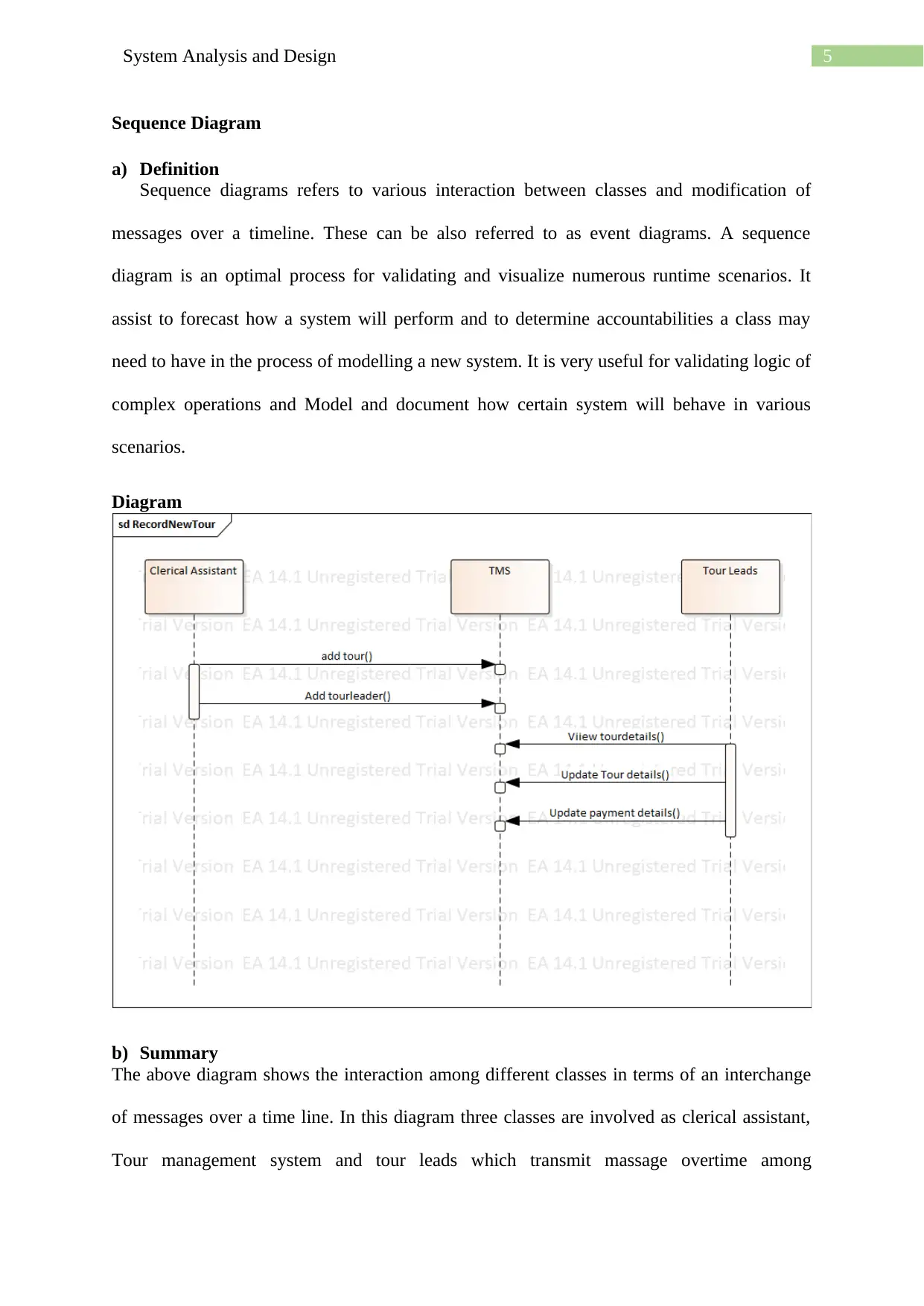
Sequence Diagram
a) Definition
Sequence diagrams refers to various interaction between classes and modification of
messages over a timeline. These can be also referred to as event diagrams. A sequence
diagram is an optimal process for validating and visualize numerous runtime scenarios. It
assist to forecast how a system will perform and to determine accountabilities a class may
need to have in the process of modelling a new system. It is very useful for validating logic of
complex operations and Model and document how certain system will behave in various
scenarios.
Diagram
b) Summary
The above diagram shows the interaction among different classes in terms of an interchange
of messages over a time line. In this diagram three classes are involved as clerical assistant,
Tour management system and tour leads which transmit massage overtime among
⊘ This is a preview!⊘
Do you want full access?
Subscribe today to unlock all pages.
Trusted by 1+ million students worldwide

6System Analysis and Design
themselves. A sequence diagram is an optimal process to validate and visualize numerous
runtime scenarios. These can assist to forecast how a system will perform and to determine
accountabilities a class may need to have in the process of modelling a new system.
themselves. A sequence diagram is an optimal process to validate and visualize numerous
runtime scenarios. These can assist to forecast how a system will perform and to determine
accountabilities a class may need to have in the process of modelling a new system.
Paraphrase This Document
Need a fresh take? Get an instant paraphrase of this document with our AI Paraphraser
7System Analysis and Design
Task 3:
Computer-Aided Software Engineering (CASE) technologies refers to tools which,
offer automated support for production of software. The aim of presenting CASE tools is
decrease of cost and time for development of software and the improvement of the excellence
of systems developed. The CASE tool market is expansionary grow thing day by day as the
requirement of such tools is necessary. Tourism is also considered as one of the world’s
largest economic activity. In many countries it is a leading business and the most substantial
approach to offer work worldwide. CASE tool is used by numerous industry including the
tourism industry. In this industry mainly three analysis tools are used for Computable General
Equilibrium models, Travel Competitiveness Index and Tourism Satellite Accounts by the
tour planners and destination managers. The effectiveness of such tools in e-learning is
optimal and assist the managers to excute suitable tours by gaining and evaluating useful
insights. Such tools can be also used together to offer competitive advantage and understand
the economical contribution of any certain location or environment However, the usefulness
of such tools cannot assist the estimation manager with policy formula. Even though the
practices to use such tolls in tourism has been around and still progressing (Bashroush et al.
2017 ).
Computer aided software engineering is considered as a domain of software tools which is
mainly utilized to implement and design application in different areas. It is very much similar
as CAD which stands for computer aided design. It is widely used for developing
maintainable, high quality and defect frre application as necessary in different domain. It is
also often considered to associate with the development of the automated tools in software
engineering used in the earlier development process (Kruser et al. 2015). It supports in
Development of test cases, Development of functional and process description, development
8System Analysis and Design
of functional and process description, development of top-level design, establishing a
relationship between requirements and models, relation of data flow and entity models.
CASE are mainly developed to upgrade and enhance the adoption of computing system
which is very significant for computer based programs that mostly used by business. The
dependency on this tools is also increasing because of the assistant to increase in the growth
and take effective strategy for advancement. The main reasons for developing the CASE tool
is followed:
The development speed increased while developing the software.
Efficiently transfer information among the tools.
Manipulate and create documentation
Develop design and enhanced analysis
Optimum utilization of existed information.
Enrich data flow and graphical techniques.
Save time while reducing the testing and coding time.
Quick installation
Several sectors uses CASE tools for certain reasons which are followed:
Increase Productivity:
Mainly, the tourism sectors uses such tools to automate several key tasks which assist to
increase the system management process including the development of such system. Hence,
increase productivity.
Reduce the maintenance cost:
Such tools assist to maintain the system very effectively in terms of effort and cost.
⊘ This is a preview!⊘
Do you want full access?
Subscribe today to unlock all pages.
Trusted by 1+ million students worldwide
9System Analysis and Design
Project Management:
As it assist to automate several tasks, hence improve the management standard of a project or
tour.
Documentation:
Generally, The documentation of quality at various stages rely on several stages which are
also depends on different individuals. In the different stages of development process the
CASE tools enhance the quality of the documentation also improve the quality of the system.
Testing:
CASE tools assist in enlightening the process of testing while automate, simplified and
checking the maintenance.
Rapid Application Development:
To increase the quality and speed of system development organizations use CASE tools.
To facilitate single design methodology:
CASE tools assist the organization to normalize the development process. It also simplifies
development of coordination. Additionally, Incorporation turn out to be easy as common
methodology is adopted.
Basically, the CASE tools are used to
Construct systems that are sustainable cause of appropriate control of configuration
item that support traceability necessities.
Deduce the time of development as it assist to avoid reuse, repetitions and assist
standardization.
Paraphrase This Document
Need a fresh take? Get an instant paraphrase of this document with our AI Paraphraser

10System Analysis and Design
Develop enhanced quality projects while supported by the coordination and
consistency.
Develop better quality documentation.
Develop enhanced quality projects while supported by the coordination and
consistency.
Develop better quality documentation.
11System Analysis and Design
References:
Bashroush, R., Garba, M., Rabiser, R., Groher, I. and Botterweck, G., 2017. Case tool
support for variability management in software product lines. ACM Computing Surveys
(CSUR), 50(1), p.14.
Kruser, J.M., Nabozny, M.J., Steffens, N.M., Brasel, K.J., Campbell, T.C., Gaines, M.E. and
Schwarze, M.L., 2015. “Best Case/Worst Case”: Qualitative Evaluation of a Novel
Communication Tool for Difficult in‐the‐Moment Surgical Decisions. Journal of the
American Geriatrics Society, 63(9), pp.1805-1811.
Weng, S.F., Kai, J., Neil, H.A., Humphries, S.E. and Qureshi, N., 2015. Improving
identification of familial hypercholesterolaemia in primary care: derivation and validation of
the familial hypercholesterolaemia case ascertainment tool (FAMCAT). Atherosclerosis,
238(2), pp.336-343.
Sellami, A., Hakim, H., Abran, A. and Ben-Abdallah, H., 2015. A measurement method for
sizing the structure of UML sequence diagrams. Information and Software Technology, 59,
pp.222-232.
Fernández-Sáez, A.M., Genero, M., Chaudron, M.R., Caivano, D. and Ramos, I., 2015. Are
Forward Designed or Reverse-Engineered UML diagrams more helpful for code
maintenance?: A family of experiments. Information and Software Technology, 57, pp.644-
663.
⊘ This is a preview!⊘
Do you want full access?
Subscribe today to unlock all pages.
Trusted by 1+ million students worldwide
1 out of 13
Related Documents


Your All-in-One AI-Powered Toolkit for Academic Success.
+13062052269
info@desklib.com
Available 24*7 on WhatsApp / Email
![[object Object]](/_next/static/media/star-bottom.7253800d.svg)
Unlock your academic potential
Copyright © 2020–2026 A2Z Services. All Rights Reserved. Developed and managed by ZUCOL.