Yachts Australia: System Analysis and Design Report (BCO2041)
VerifiedAdded on 2022/12/19
|16
|1946
|283
Report
AI Summary
This report presents a comprehensive system analysis and design for Yachts Australia, focusing on creating a management system to streamline day-to-day operations. The report details the integration of different organizational units through entity relations, emphasizing the use of strategic approaches for system effectiveness and efficiency. It covers various phases, starting with project specifications, and includes acquisition strategies, architectural design, hardware and software specifications, interface design, user interface flow, wireframe diagrams, structure charts, and program specifications. The Agile Methodology is highlighted for its ability to ensure interactiveness and iterations. The report also discusses the importance of user interface design for maximizing system usability and effectiveness, along with hardware and software requirements. The analysis provides insights into the design and implementation of a system tailored to meet Yachts Australia's specific needs, with a focus on testing and validation to ensure the final product meets all requirements.
SYSTEM ANALYSIS AND DESIGN 1
Affiliate Information
Affiliate Information
Paraphrase This Document
Need a fresh take? Get an instant paraphrase of this document with our AI Paraphraser

SYSTEM ANALYSIS AND DESIGN 2
SYSTEM ANALYSIS AND DESIGN 3
Executive Summary
The core purpose that drives this project is in order to realize a management system that helps in the
day to day activities involved in Yacht Australia business company. The different units of the
organization are merged and related to each other through entity relations that form up a functional
system. the are various techniques used in the designing and implementation are well stated in the
report.
The success of the system is fully dependent on the strategic approaches take, they in turn help in
ensuring that the system is effective and efficient. The various phases are well stated in the report, the
initial phase having the specifications of the project. The project below is focused on ensuring that the
end product is able to cater and realize the Yachts company’s requirements.
⊘ This is a preview!⊘
Do you want full access?
Subscribe today to unlock all pages.

Trusted by 1+ million students worldwide
SYSTEM ANALYSIS AND DESIGN 4
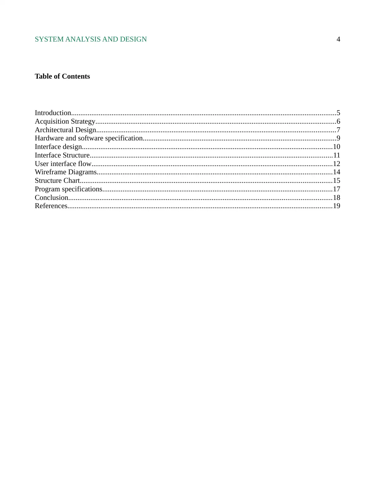
Table of Contents
Introduction................................................................................................................................................5
Acquisition Strategy...................................................................................................................................6
Architectural Design..................................................................................................................................7
Hardware and software specification.........................................................................................................9
Interface design........................................................................................................................................10
Interface Structure....................................................................................................................................11
User interface flow...................................................................................................................................12
Wireframe Diagrams................................................................................................................................14
Structure Chart.........................................................................................................................................15
Program specifications.............................................................................................................................17
Conclusion...............................................................................................................................................18
References................................................................................................................................................19
Paraphrase This Document
Need a fresh take? Get an instant paraphrase of this document with our AI Paraphraser
SYSTEM ANALYSIS AND DESIGN 5
Introduction
The effectiveness and efficiency of a system are determined by its ability to meet the requirement of the
company, its effectiveness will be fully dependent on the methodologies and techniques that will be
deployed in the designing and implementation phase. There are both hardware and software
requirements for the realization of the project.
The best methodology used to realize an interactive and iterative system by the users is the Agile
Methodology. However, its ability to ensure interactiveness and iterations is dependent on how ell the
phases have been stated, thus determining the entire procedure in the development of the system.
The specific functionalities in the system project are both from the hardware and software tools
requirement. In order to smooth line their functionality, it is necessary that the hardware and software
logistics are laid out well (Glover, Sarma and Overbye, 2012). The user will interact with the system on
a computer through a user interface.
In order for the maximum use of the system, it is mandatory to ensure that the user interface of the
system is appealing and easy to understand. This phase has to be attendant to before commencing the
development phases.
SYSTEM ANALYSIS AND DESIGN 6
Acquisition Strategy
This is a collection of the schemes and plans that are designed and defined as a section of the business
activities, this is usually at the initial development phase. Thorugh the outlined schemes, the
management and technical protocols on how to realize the objectives are stated.
The following is a list of the various approaches that are deployed in the phase of system development
and implementation (Whitten, Bentley and Dittman, 2010.).
Requirements acquisition – this is the starting pahs and the activities involved in this stage
include identifying and gathering all the tools and equipment that will be used in the design and
implementation. This may vary on both the hardware and software tools.
Interface design – this is the process of designing an intermediary system that the user of the
system will use to work with the system. There is a feature of dynamicity and adaptability that
need to be portrayed by the User Interface.
Implementation – this is the state that involves the majority of developing and creating the
actual system. the development of the system is done with the use of the tools gathered at the
requirement acquisition stage. After this phase is complete, the system is taken to the Test face.
Testing – this is the stage where the competence or requirements are tested. It may also be
referred to as the validation stage, this is because it determines the success of the design and
implementation phases. After the test is successful it is taken to the deployment phase.
Deployment - this is the final phase on with the system is handed to the user’s through a public
domain. From there, the users can fully interact and use the system.
⊘ This is a preview!⊘
Do you want full access?
Subscribe today to unlock all pages.

Trusted by 1+ million students worldwide
SYSTEM ANALYSIS AND DESIGN 7
Architectural Design
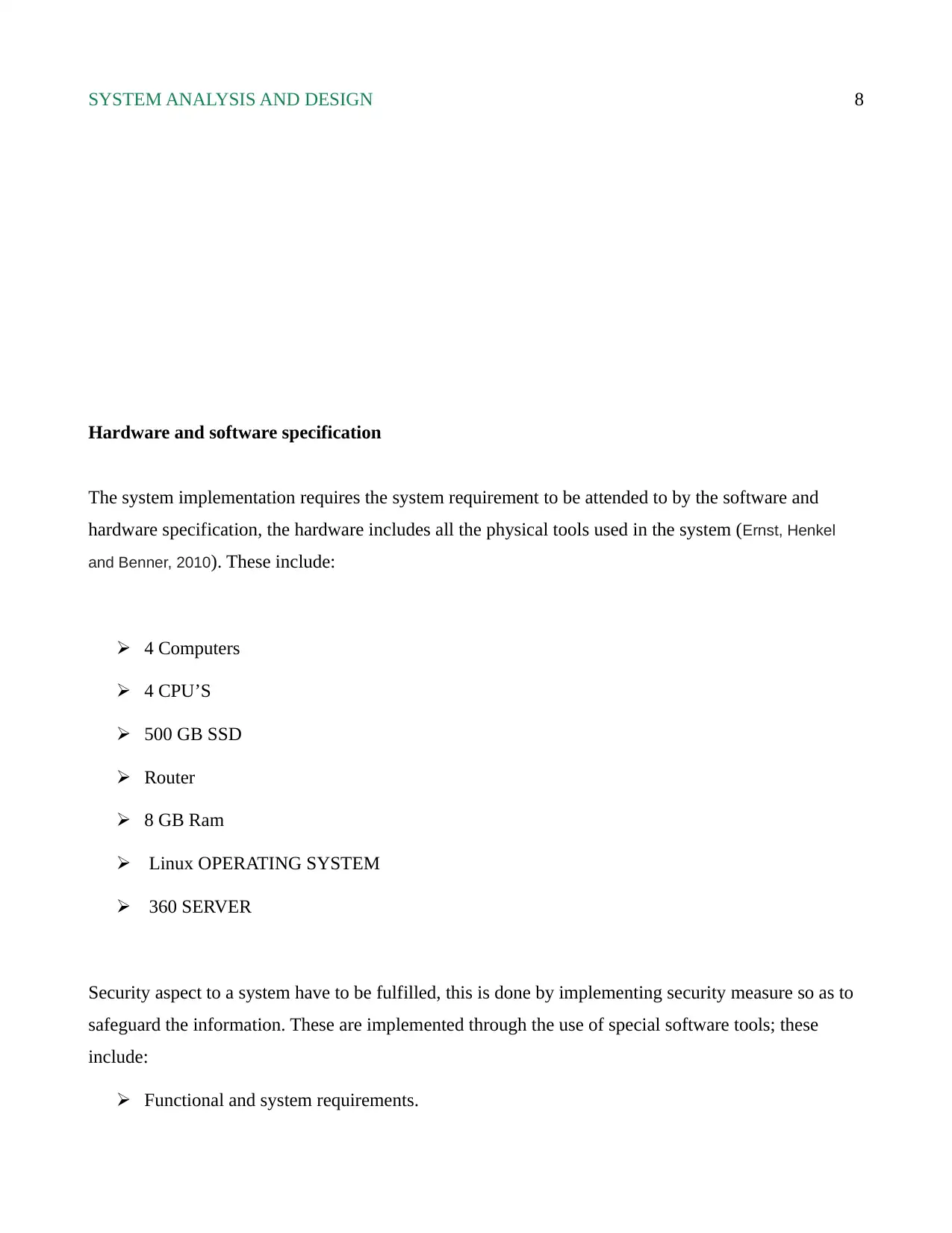
The architectural design comprises of the form and structures that are used to develop a system. it is
also defined as the blueprint of a system because it outlines the structural representation of the system.
The architecture design is also used as a communication tool between the development and the design
team. The architecture design is well suited to the requirement of the system (Granadeiro, Duarte, Correia
and Leal, 2013).
Paraphrase This Document
Need a fresh take? Get an instant paraphrase of this document with our AI Paraphraser
SYSTEM ANALYSIS AND DESIGN 8
Hardware and software specification
The system implementation requires the system requirement to be attended to by the software and
hardware specification, the hardware includes all the physical tools used in the system (Ernst, Henkel
and Benner, 2010). These include:
4 Computers
4 CPU’S
500 GB SSD
Router
8 GB Ram
Linux OPERATING SYSTEM
360 SERVER
Security aspect to a system have to be fulfilled, this is done by implementing security measure so as to
safeguard the information. These are implemented through the use of special software tools; these
include:
Functional and system requirements.
SYSTEM ANALYSIS AND DESIGN 9
System qualities
System use cases.
Constraints and assumptions.
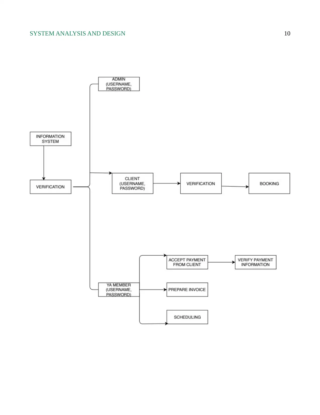
Interface design
This is the intermediary between the system component and the user. A system that is made up of a
good user interface makes it easy for the user to use the system effectively. In order to maximize the
success of the system, the user interface has to be simple and appealing.
The interface designing phase is the commencing phase before designing and implementation of the
system. this is because the interface is used as a guideline for the development phase. This can be done
with the use of various design tools such as Adobe and photoshop.
These software tools are normally used to develop the interrelationship between the components of the
system and the user of the system.
The guiding goal for the interface designer is to ensure that the user interface is easy and very
appealing to the user's eyes. This is by ensuring that the user interface offers a great feel and experience
to the user.
In addition, the user interface aspect makes it act as a responsive channel that allows communication
between the components and the users. This makes it easier to interact and maximize system resources.
Interface Structure
⊘ This is a preview!⊘
Do you want full access?
Subscribe today to unlock all pages.

Trusted by 1+ million students worldwide
SYSTEM ANALYSIS AND DESIGN 10
Paraphrase This Document
Need a fresh take? Get an instant paraphrase of this document with our AI Paraphraser
SYSTEM ANALYSIS AND DESIGN 11
User interface flow
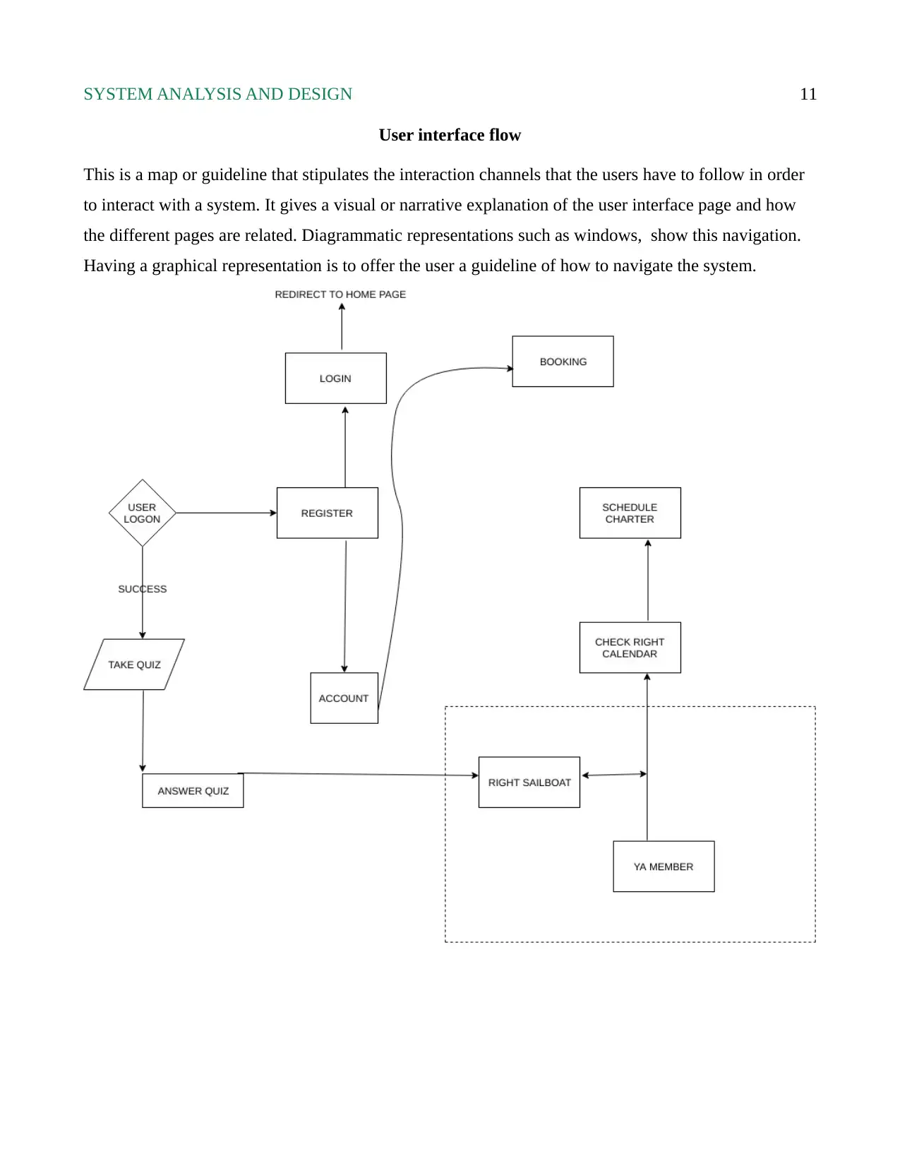
This is a map or guideline that stipulates the interaction channels that the users have to follow in order
to interact with a system. It gives a visual or narrative explanation of the user interface page and how
the different pages are related. Diagrammatic representations such as windows, show this navigation.
Having a graphical representation is to offer the user a guideline of how to navigate the system.
SYSTEM ANALYSIS AND DESIGN 12
Wireframe Diagrams
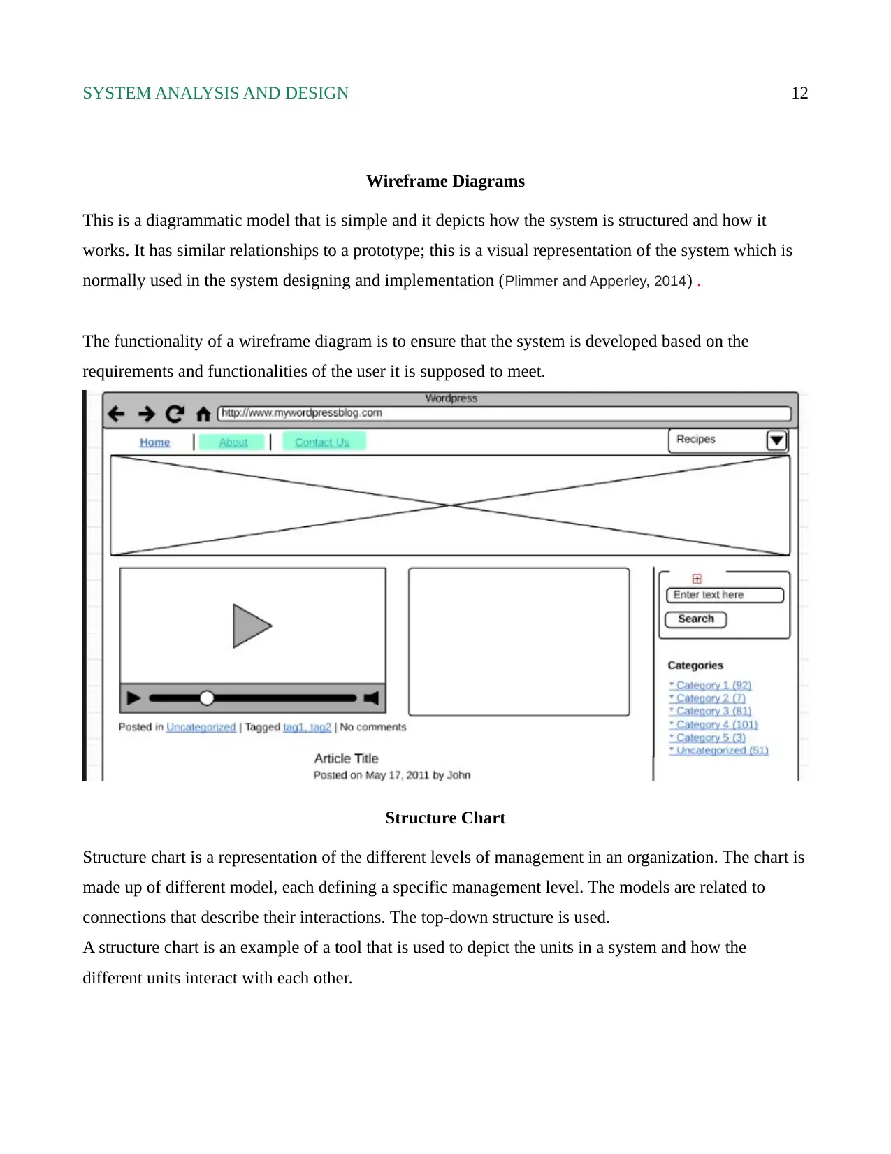
This is a diagrammatic model that is simple and it depicts how the system is structured and how it
works. It has similar relationships to a prototype; this is a visual representation of the system which is
normally used in the system designing and implementation (Plimmer and Apperley, 2014) .
The functionality of a wireframe diagram is to ensure that the system is developed based on the
requirements and functionalities of the user it is supposed to meet.
Structure Chart
Structure chart is a representation of the different levels of management in an organization. The chart is
made up of different model, each defining a specific management level. The models are related to
connections that describe their interactions. The top-down structure is used.
A structure chart is an example of a tool that is used to depict the units in a system and how the
different units interact with each other.
⊘ This is a preview!⊘
Do you want full access?
Subscribe today to unlock all pages.

Trusted by 1+ million students worldwide
1 out of 16
Related Documents
Your All-in-One AI-Powered Toolkit for Academic Success.
+13062052269
info@desklib.com
Available 24*7 on WhatsApp / Email
![[object Object]](/_next/static/media/star-bottom.7253800d.svg)
Unlock your academic potential
Copyright © 2020–2026 A2Z Services. All Rights Reserved. Developed and managed by ZUCOL.


