System Design and Analysis of i-Dine Information System Project
VerifiedAdded on 2023/04/22
|14
|2339
|233
Project
AI Summary
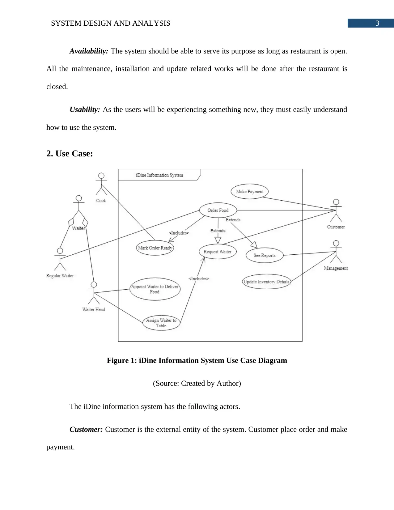
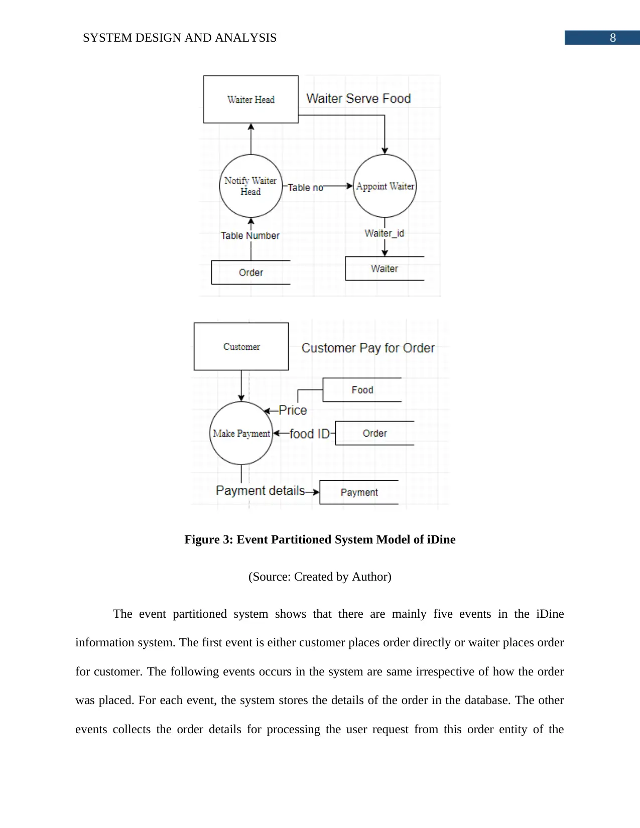
This assignment provides a comprehensive system design and analysis of the i-Dine information system. It begins by outlining both functional and non-functional requirements, crucial for the system's operation and security. A detailed use case diagram illustrates the interactions between actors like customers, waiters, and management. The domain model class diagram depicts the structural relationships between classes such as food, orders, and payments. Event partitioned system models are used to show the events within the system. The assignment then explores the SDLC model activities, including environment selection, application component design, user interface design, database design, and software development. The document concludes with a bibliography of cited sources. The i-Dine system is designed to enhance customer service and streamline operations within a restaurant setting.

Running head: SYSTEM DESIGN AND ANALYSIS
Assignment 2
Name of the Student
Name of the University
Author’s Note:
Assignment 2
Name of the Student
Name of the University
Author’s Note:
Secure Best Marks with AI Grader
Need help grading? Try our AI Grader for instant feedback on your assignments.

1SYSTEM DESIGN AND ANALYSIS
Table of Contents
1. Functional and Non-Functional Requirements:...........................................................................2
1.1 Functional Requirement:.......................................................................................................2
1.2 Non-Functional Requirement:...............................................................................................2
2. Use Case:.....................................................................................................................................3
3. Domain Model Class Diagram:...................................................................................................5
4. Event Partitioned System Models:...............................................................................................6
5. SDLC Model Activities:..............................................................................................................9
Bibliography:.................................................................................................................................12

2SYSTEM DESIGN AND ANALYSIS
1. Functional and Non-Functional Requirements:
1.1 Functional Requirement:
Make Order Directly: The customer must be able to place order directly through the table
top tablets. The tablets placed in the tables must have the information of in which table it is
installed and the menu of iDine.
Request Waiter: The system must allow the customers with zero technical knowledge to
request for orders. The request for waiters are shown as notification to the head waiter.
Make Order Through Waiter: The waiter must place orders for customers if they
request. The waiter will add the table number along with the order details.
Food Preparation: The system will send the order details to the kitchen after it is
confirmed. The ordered foods will be printed on a paper in respective kitchen areas. The cook
will prepare the food and ask the waiter to serve it to the table.
Payment: Each order must have a successful payment. For the customer satisfaction, the
system must accept payment through cards or cash both.
1.2 Non-Functional Requirement:
Security: The system will process the payment request and hold the details of cards. For
this reason, the system must protect the information from outside and inside security threats.
Each payment will be processed through many security layers. The data transmission will be
occurring through encryption and decryption technology.

3SYSTEM DESIGN AND ANALYSIS
Availability: The system should be able to serve its purpose as long as restaurant is open.
All the maintenance, installation and update related works will be done after the restaurant is
closed.
Usability: As the users will be experiencing something new, they must easily understand
how to use the system.
2. Use Case:
Figure 1: iDine Information System Use Case Diagram
(Source: Created by Author)
The iDine information system has the following actors.
Customer: Customer is the external entity of the system. Customer place order and make
payment.
Secure Best Marks with AI Grader
Need help grading? Try our AI Grader for instant feedback on your assignments.

4SYSTEM DESIGN AND ANALYSIS
Waiter Head: The head of the waiter will assign a waiter to table for making order and
serving food.
Cook: The cook will prepare the food for customers.
Waiter: The waiter will serve food and make for customers.
Management: Management will access reports and update the inventory details.
The iDine information system has the following use cases.
Order Food: The customer and the waiter will be actors of this use case. The customer
can directly place order through the table tablets. The waiters can also make the order for
customer. The related use cases are Mark Order Ready, Request Waiter and See Reports.
Request Waiter: The customer is the actor of this use case. The system has a button that
allows customer requesting for waiter.
Assign Waiter to Table: The head waiter response to customer request and send a waiter
to attend the customer.
Mark Order Ready: The cooks is responsible for preparing the food and marking the
order as ready after it is prepared.
Appoint Waiter to Deliver Food: After the food is marked as ready, the waiter head
assigns a waiter to serve the food to the table.
See Reports: Management executives can access reports.
Update Inventory Details: The management can also update the details of the inventory.
Make Payment: The customer will make payment for the order they placed.

5SYSTEM DESIGN AND ANALYSIS
3. Domain Model Class Diagram:
Figure 2: Domain Model Class Diagram of iDine
(Source: Created by Author)
The class diagram shows the composition, inheritance and association relationship among
the classes. There are total eleven classes in the class diagram that describes the complete
structural pattern of the iDine application. The figure 2 illustrates that each of the classes has
own attributes that describes what kind of information each class will possess. The operations

6SYSTEM DESIGN AND ANALYSIS
declared in the classes will make use of those data to direct the processes. The foods are created
using the ingredients. And the orders are consist of only foods. That is why food, ingredient and
order has composition relationship among them. Every order is to be paid. One payment is done
for each individual order. The payment can be done using cash or card. The card and cash are
child classes of payment class. Same way the regular waiter and head waiter are child classes of
waiter class.
4. Event Partitioned System Models:
Paraphrase This Document
Need a fresh take? Get an instant paraphrase of this document with our AI Paraphraser

7SYSTEM DESIGN AND ANALYSIS

8SYSTEM DESIGN AND ANALYSIS
Figure 3: Event Partitioned System Model of iDine
(Source: Created by Author)
The event partitioned system shows that there are mainly five events in the iDine
information system. The first event is either customer places order directly or waiter places order
for customer. The following events occurs in the system are same irrespective of how the order
was placed. For each event, the system stores the details of the order in the database. The other
events collects the order details for processing the user request from this order entity of the

9SYSTEM DESIGN AND ANALYSIS
database. The next event is food preparing. The cook is responsible for completing this event.
Once the food is prepared, the cook marks the food as ready. Serving the food is the next event
in the system. After the food is marked as ready, the waiter head receives a notification along
with the table number form which the food was ordered. The waiter head assigns a waiter for
serving the food to the table. Once the customer has eaten the food and ready to leave, the
customer makes the payment for the order. All these processes will be connected to a data store.
5. SDLC Model Activities:
Environment: The selection of the environment is done in both the planning and system
analysis phases of SDLC model. Either cloud or in-house environment can be selected for
developing the system. In case of in-house, the system will be implemented by installing the
hardware in the premise of the Vallée de Goût. The organization will be responsible for the
resources required for system development project. On the other hand, the system developed for
cloud environment is responsibility of the cloud host. The cloud environment allows the users of
the system to access it from remote locations. As the system will be used by the customers to
place order from within the restaurant and the staff will access it while they are work. Therefore,
the in-house environment is suitable for operational purpose but the cost of in-house system is
extremely high. Considering the budget of the project, the Vallée de Goût can go for cloud
environment based system.
Designing Application Components: The designing is done in the system design phase
of SDLC model. The designing refers to the UML models, network design, event portioned
system models, entity relational model and many more. All these designs are done based on the
requirements gathered and validated system analysis section. The application is designed by
considering each aspect of it. The UML diagram captures the structural and dynamic patterns of
Secure Best Marks with AI Grader
Need help grading? Try our AI Grader for instant feedback on your assignments.

10SYSTEM DESIGN AND ANALYSIS
the iDine application. The use case represents the interaction between the users and the system.
The actors of the use case diagram are the users and the use case illustrates for which purpose
they access the system. The class diagram on the other hand is used for capturing the structural
pattern of iDine information system. The event partitioned system is used for capturing the
events that will occur in the system and the flow of data between the entities.
User Interface: The user interface of the application is designed in designing and
development phase of the SDLC model. In the designing phase, the interface is designed through
mockups and clickable prototype. After these two designs are approved, the actual interface is
designed in the development phase. The user interface is validated and verified based on the
feedbacks of the actual users. There are various factors that needs to be considered when
designing the interface. The design should have extreme quality so that usability of the system
can be adequate enough. The application must follow same color and design specification
throughout all the sections. The user interaction or UX quality also depends on the interface of
the application.
The Database: Database is one of the most important part of any system. It is designed in
the design phase and implemented in the development phase. The selection of the database
management system depends on the programming language used for developing the application.
The database of the iDine system will be deployed to the cloud, same place where the application
will be deployed. The database management system will store the data, manipulate those data
and retrieve the data from the database. The system will also collect data from the users, process
those data to generate information and store the information in the database for future use.
The Software: The software is the main component of the system. The units of software
are generated in the development phase. The developed software is tested in the testing phase for

11SYSTEM DESIGN AND ANALYSIS
identifying the errors in code and gaps in application. The software development is done based
on the designs made in the designing phase. The software will go through various testing phases
to make sure that final products meets the functional and non-functional requirements of the
system.
identifying the errors in code and gaps in application. The software development is done based
on the designs made in the designing phase. The software will go through various testing phases
to make sure that final products meets the functional and non-functional requirements of the
system.

12SYSTEM DESIGN AND ANALYSIS
Bibliography:
Alshamrani, A., & Bahattab, A. (2015). A comparison between three SDLC models waterfall
model, spiral model, and Incremental/Iterative model. International Journal of Computer
Science Issues (IJCSI), 12(1), 106.
Bello, S. I., Bello, R. O., Babatunde, A. O., Olugbebi, M., & Bello, B. O. (2017). A University
Examination Web Application Based on Linear-Sequential Life Cycle Model.
Chowdhury, A. Z. M., Bhowmik, A., Hasan, H., & Rahim, M. S. (2018). Analysis of the
Veracities of Industry Used Software Development Life Cycle Methodologies. arXiv
preprint arXiv:1805.08631.
Da Silva, A. R. (2015). Model-driven engineering: A survey supported by the unified conceptual
model. Computer Languages, Systems & Structures, 43, 139-155.
Dennis, A., Wixom, B. H., & Tegarden, D. (2015). Systems analysis and design: An object-
oriented approach with UML. John wiley & sons.
Esper, A., Nelissen, G., Nélis, V., & Tovar, E. (2015, November). How realistic is the mixed-
criticality real-time system model?. In Proceedings of the 23rd International Conference
on Real Time and Networks Systems (pp. 139-148). ACM.
Faitelson, D., & Tyszberowicz, S. (2017, May). UML Diagram Refinement (focusing on class-
and use case diagrams). In Proceedings of the 39th International Conference on Software
Engineering (pp. 735-745). IEEE Press.
Gupta, D., Ahlawat, A. K., & Sagar, K. (2017). Usability prediction & ranking of SDLC models
using fuzzy hierarchical usability model. Open Engineering, 7(1), 161-168.
Paraphrase This Document
Need a fresh take? Get an instant paraphrase of this document with our AI Paraphraser

13SYSTEM DESIGN AND ANALYSIS
Khan, F., Jan, S. R., Tahir, M., Khan, S., & Ullah, F. (2016). Survey: Dealing Non-Functional
Requirements at Architecture Level. VFAST Transactions on Software Engineering, 9(2),
7-13.
Khan, S., Babar, M., Khan, F., Arif, F., & Tahir, M. (2016). Collaboration Methodology for
Integrating Non-Functional Requirements in Architecture. the Journal of Applied
Environmental and Biological Sciences (JAEBS), 6, 63-67.
Long, J. E. (2018). Relationships between common graphical representations used in system
engineering. INSIGHT, 21(1), 8-11.
Plataniotis, G., Ma, Q., Proper, E., & de Kinderen, S. (2015, May). Traceability and modeling of
requirements in enterprise architecture from a design rationale perspective. In Research
Challenges in Information Science (RCIS), 2015 IEEE 9th International Conference
on (pp. 518-519). IEEE.
1 out of 14
Related Documents

Your All-in-One AI-Powered Toolkit for Academic Success.
+13062052269
info@desklib.com
Available 24*7 on WhatsApp / Email
Unlock your academic potential
© 2024 | Zucol Services PVT LTD | All rights reserved.