IMAT5205 System Analysis and Design: Modelling Assignment 2
VerifiedAdded on 2023/04/23
|12
|1898
|427
Report
AI Summary
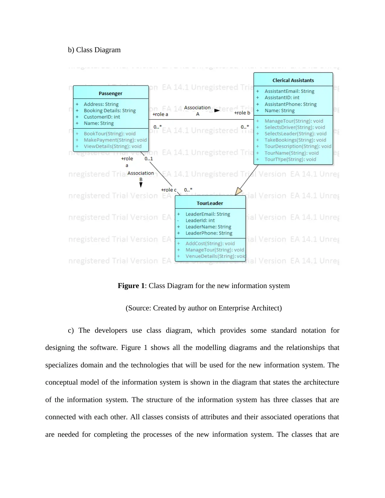
This document presents a solution to a System Analysis and Design modelling assignment, focusing on the 'Record New Tour' use case. It includes a class diagram illustrating the system's structure with classes like tour leader, passenger, and clerical assistants, along with their attributes and operations. A communication diagram depicts the interactions between objects within the system, emphasizing communication processes. Furthermore, a sequence diagram outlines the chronological exchange of information, detailing message passing between lifelines. The report also evaluates the CASE environment, discussing its tools and their role in designing the information system, along with their advantages and disadvantages. The assignment uses UML diagrams to model and analyze the system, providing a clear and structured approach to system design. Desklib provides a platform to explore such assignments and helps students with their study resources.

System Analysis and Design
Name of Student-
Name of University-
Author’s Note-
Name of Student-
Name of University-
Author’s Note-
Secure Best Marks with AI Grader
Need help grading? Try our AI Grader for instant feedback on your assignments.

Part 1. Use Case Realisation for the ‘Record New Tour’ Use Case
Class Diagram
a) Analysis Class Diagram: Class diagram includes a diagram that basically contains the
classes that are involved in the system that is to be designed. Class diagram is a part of UML
(Unified Modelling language) that defines structure of a particular system that is to be designed.
Class diagram provides the reader and the developer an easy way of designing the software that
defines structure, classes, methods as well as operations of the class that the system will perform.
Class diagram also shows the relationship between the classes that are defined in the diagram.
Class diagram is also known as the conceptual diagram.

b) Class Diagram
Figure 1: Class Diagram for the new information system
(Source: Created by author on Enterprise Architect)
c) The developers use class diagram, which provides some standard notation for
designing the software. Figure 1 shows all the modelling diagrams and the relationships that
specializes domain and the technologies that will be used for the new information system. The
conceptual model of the information system is shown in the diagram that states the architecture
of the information system. The structure of the information system has three classes that are
connected with each other. All classes consists of attributes and their associated operations that
are needed for completing the processes of the new information system. The classes that are

associated with each other consists of tour leader, passenger, and the clerical assistants. All the
classes have their own operations and the attributes that are needed to carry out a process in the
system.
Communication Diagram
a) Communication Diagram: This is commonly known as collaboration diagram. It is
often known as interaction diagram that shows the relationship as well as the interaction that is in
software objects in the UML languages. These diagrams states the communication in between
the objects that are associated with the new information system. The developers use
communication diagram to make the communication process clear to other developers and the
reader as well. All modelling paradigms that are involved in the system design are stated in the
communication diagram. The communication diagram shows lifelines that are connected with
each other and helps to define the architecture of the system. The message passing is also shown
in the communication diagram.
Secure Best Marks with AI Grader
Need help grading? Try our AI Grader for instant feedback on your assignments.

b)
Figure 2: Communication Diagram for the new information system
(Source: Created by author on Enterprise Architect)
c) Figure 2 shown above is the communication diagram that is assumed for the
information system of the tour business. Communication diagram depicts simple interactions
with small number of objects. The communication diagram shown above shows all the processes
that the business wants to incorporate within the new information system. All the processes in
the system needs to be automatic, for which the new information system is to be developed.
Communication diagram is one of the process that make the system automated. The
communication diagram for the system is kept very simple so that it becomes easy for others to
interpret it. The communication diagrams are created by different developers in different ways
and there is a link in between the objects that are present in the system.

Part 2. Sequence Diagram for the ‘Record New Tour’ Use Case
a) Sequence Diagram: Sequence diagram used in system analysis and designing the
software mainly helps in emphasizing the chronological course of information that is to be
exchanged. Sequence diagram is very easy to understand for readers as well as analyst. Sequence
diagram is used by analyst with simple notations and are used for designing the application of a
system. The communication is sequentially depicted in the sequence diagram that shows the
messages passing synchronizing in the system. Sequence diagrams shows different scenarios
that states the business use case and the sequence diagram in a message exchange between the
business system and the users. The model of the sequence diagram stares the flow of logic in
between the lifelines of the system in visual manner enabling developer to validate the logic of
the developers.

b)
Figure 3: Sequence Diagram for the new information system
(Source: Created by author on Enterprise Architect)
Figure 3: Sequence Diagram for the new information system
(Source: Created by author on Enterprise Architect)
Paraphrase This Document
Need a fresh take? Get an instant paraphrase of this document with our AI Paraphraser

c) Figure 3 shows the sequence diagram of Record New Tour information system.
Sequence diagram consists of messages that are needed for establishing a communication in
between the lifelines that are involved within the system. The message passing that is shown in
the diagram states the target and the source of messages that is exchanged in the system. The
actors in the system interact with each other from the message that are shown in the diagram.
The messages shown in the diagram states the messages that will pass in between the objects of
the sequence diagram. The target of the messages are shown in the sequence diagram. The
diagram shows message that passes from one object to another in a sequence. The response of
the objects are also shown in the sequence diagram of the Record New Tour system. The
sequence diagram that is shown above is the dynamic modelling, which is used for identifying
the system behaviour of an information system.
Part 3: Evaluation
CASE environment is known as collection of the tools used for designing an information
system. The CASE environment also includes the components that includes integrated approach,
which supports interaction between the objects within a system (Turco, Pietro and Martignano
2018). The interaction that is involved in the system is to be shown out within the system. The
interaction that takes place between the component and the environment is shown in the CASE
tools. The environment of CASE includes different different CASE tools that helps in operating
the platform, which has common hardware and a software system. One of the main disadvantage
of CASE tool is that the tool has lack of interoperability that are included in the CASE tool.
CASE commonly known as Computer Aided Software Engineering is mainly a domain,
which includes many software tools used for designing products needed in the hardware of the
system. The CASE tool software are very easy to handle and are mainly inspired by Computer

Aided Tools that designs the software hardware product of the system. The CASE tools are high-
ended software that has all the quality of maintaining as well as detect the impurities in the
software. The methods that are used to develop the system are used to develop the processes for
developing the software.
Some of the particular tasks that are supported by the CASE tools that includes the life
cycle of the software and includes workbenches (Kounev 2016). The workbenches that focuses
on some particular part included in life cycle software support more than one number of tools.
The tool supports environment that has more than one tool and some of the workbenches. The
tool also supports the life cycle of the software completely.
The CASE environment includes tools that supports the tasks needed for developing the
life cycle of the software. The tasks involved are divided in some of the categories. One of those
categories includes modelling analysis as well as business including the tool of the graphical
modelling of entity relationship and the object modelling. Development design is used in the life
cycle of the software that helps to debug the environments and the construction phase is also
used for designing the software. The CASE tool mainly includes validation as well as
verification used for analysing the specifications and the code included in the performance as
well as correctness of the system.
The tools in the CASE environment are combination of many software helping to
automate activities that includes many phases of the life cycle (Hare and Kaplan 2017). The
functional requirement needed for developing a software is an example of software tools that are
involved in CASE environment. The functional requirement are needed to develop graphic
model for the applications and also helps in visualizing the application look for development
process that will be finished. The system developers or the system analyst mainly uses the tools

for automating the design used for transforming the functional requirement prototype that are
used for detailing the document. The developers of the system uses CASE tool to generate the
automated codes, which helps in generating document designs in some of the codes. The
automated tools that are involved in the CASE diagram are used together or are used by an
individual separately.
used for detailing the document. The developers of the system uses CASE tool to generate the
automated codes, which helps in generating document designs in some of the codes. The
automated tools that are involved in the CASE diagram are used together or are used by an
individual separately.
Secure Best Marks with AI Grader
Need help grading? Try our AI Grader for instant feedback on your assignments.

Bibliography
Del Turco, R.R., Di Pietro, C. and Martignano, C., 2018. Designing a multi-layered User
Interface for EVT 2: a development report. AIUCD 2018, p.105.
Frank, U., Atkinson, C., Grossmann, G. and Clark, T., 2016. Designing Models and Systems to
Support IT Management: A Case for Multilevel Modeling. In MULTI@ MoDELS (pp. 3-24).
Hare, E. and Kaplan, A., 2017. Designing Modular Software: A Case Study in Introductory
Statistics. Journal of Computational and Graphical Statistics, 26(3), pp.493-500.
Kaur, T. and Sehra, S.K., 2015. Designing and development of database testing
tool. International Journal of Computer Applications, 120(19).
Kounev, S., Huber, N., Brosig, F. and Zhu, X., 2016. A model-based approach to designing self-
aware IT systems and infrastructures. Computer, 49(7), pp.53-61.
Mayan, J.A., Menezes, R.J. and George, M.B., 2016. Designing a Customized Testing Tool for
Windows Phones Utilizing Background Agents. In Proceedings of the International Conference
on Soft Computing Systems (pp. 33-46). Springer, New Delhi.
Pedreira, O., García, F., Brisaboa, N. and Piattini, M., 2015. Gamification in software
engineering–A systematic mapping. Information and software technology, 57, pp.157-168.
Ptak, P., 2018, May. APPLICATION OF THE SOFTWARE PACKAGE LTSPICE FOR
DESIGNING AND ANALYSING THE OPERATION OF ELECTRONIC SYSTEMS.
In Proceedings of the International Scientific Conference. Volume V (Vol. 402, p. 408).
Sahaf, Z., Garousi, V., Pfahl, D., Irving, R. and Amannejad, Y., 2014, May. When to automate
software testing? decision support based on system dynamics: an industrial case study.

In Proceedings of the 2014 International Conference on Software and System Process (pp. 149-
158). ACM.
158). ACM.
1 out of 12
Related Documents

Your All-in-One AI-Powered Toolkit for Academic Success.
+13062052269
info@desklib.com
Available 24*7 on WhatsApp / Email
Unlock your academic potential
© 2024 | Zucol Services PVT LTD | All rights reserved.