System Analysis and Modeling Report for Mindy Hair Salon Business
VerifiedAdded on 2022/12/18
|21
|3164
|54
Report
AI Summary
This report provides a detailed system analysis of the Mindy Hair Salon, a business with multiple locations. The analysis begins with the business background, current business operations, and identifies key challenges such as outdated technology, appointment inefficiencies, and limitations with online presence. The report then outlines the scope, functional and non-functional requirements, and methods for identifying use cases. It includes documentation such as a key events table, data dictionary, and process descriptions. The core of the report involves system modeling, including data flow diagrams and entity relationship diagrams. These diagrams visually represent the flow of information and relationships within the Mindy Hair system. The analysis aims to provide insights for improving the system's efficiency and customer satisfaction by addressing existing problems and suggesting potential solutions.

Running head: SYSTEM ANALYSIS AND MODELLING
System Analysis and Modelling
Name of the Student
Name of the University
Author Note
System Analysis and Modelling
Name of the Student
Name of the University
Author Note
Paraphrase This Document
Need a fresh take? Get an instant paraphrase of this document with our AI Paraphraser
1SYSTEM ANALYSIS AND MODELLING
Table of Contents
Introduction................................................................................................................................2
Business Background.................................................................................................................2
Current Business....................................................................................................................3
Challenges & Problems..........................................................................................................3
Scope..........................................................................................................................................4
Requirements:........................................................................................................................4
Identification methods of use-cases:......................................................................................5
Documentation...........................................................................................................................5
Key events Table....................................................................................................................5
Data dictionary.......................................................................................................................6
Process Description................................................................................................................7
Conclusion..................................................................................................................................7
References..................................................................................................................................8
Appendices.................................................................................................................................9

2SYSTEM ANALYSIS AND MODELLING
Executive Summary
The following report is to discuss the analysis of the provided case study of the Mindy
Hair system and methods of the analysis. The objectives of this report is to discuss the current
business rules, challenges faced by the current system, scope and goal of the system,
functional and non-functional requirements, identification of the use cases and the possible
solutions. The report also covers the modelling of the current system into Data flow diagram
and ERD diagram. The report also represents the process and events on the basis of the
system.
⊘ This is a preview!⊘
Do you want full access?
Subscribe today to unlock all pages.
Trusted by 1+ million students worldwide
3SYSTEM ANALYSIS AND MODELLING
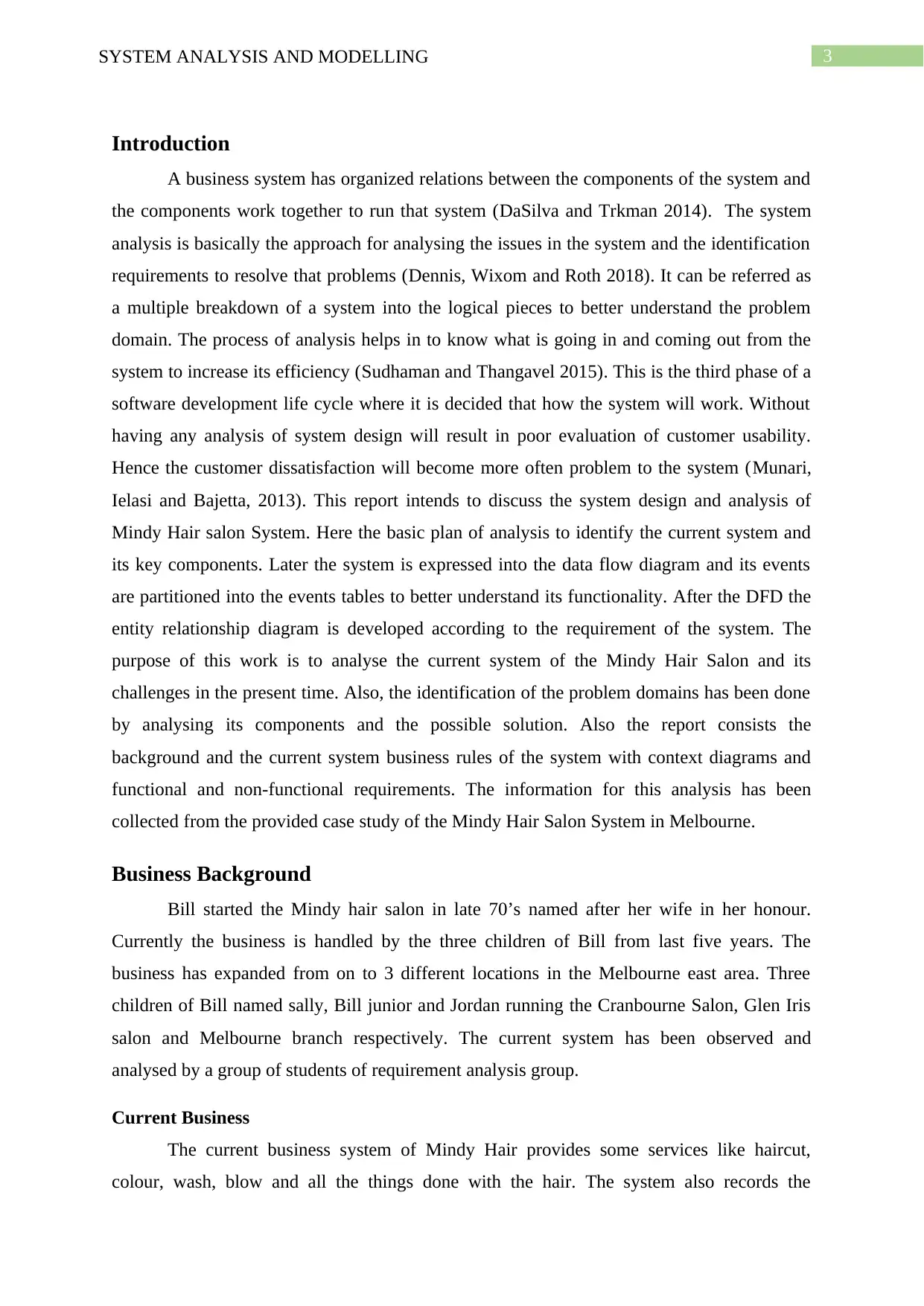
Introduction
A business system has organized relations between the components of the system and
the components work together to run that system (DaSilva and Trkman 2014). The system
analysis is basically the approach for analysing the issues in the system and the identification
requirements to resolve that problems (Dennis, Wixom and Roth 2018). It can be referred as
a multiple breakdown of a system into the logical pieces to better understand the problem
domain. The process of analysis helps in to know what is going in and coming out from the
system to increase its efficiency (Sudhaman and Thangavel 2015). This is the third phase of a
software development life cycle where it is decided that how the system will work. Without
having any analysis of system design will result in poor evaluation of customer usability.
Hence the customer dissatisfaction will become more often problem to the system (Munari,
Ielasi and Bajetta, 2013). This report intends to discuss the system design and analysis of
Mindy Hair salon System. Here the basic plan of analysis to identify the current system and
its key components. Later the system is expressed into the data flow diagram and its events
are partitioned into the events tables to better understand its functionality. After the DFD the
entity relationship diagram is developed according to the requirement of the system. The
purpose of this work is to analyse the current system of the Mindy Hair Salon and its
challenges in the present time. Also, the identification of the problem domains has been done
by analysing its components and the possible solution. Also the report consists the
background and the current system business rules of the system with context diagrams and
functional and non-functional requirements. The information for this analysis has been
collected from the provided case study of the Mindy Hair Salon System in Melbourne.
Business Background
Bill started the Mindy hair salon in late 70’s named after her wife in her honour.
Currently the business is handled by the three children of Bill from last five years. The
business has expanded from on to 3 different locations in the Melbourne east area. Three
children of Bill named sally, Bill junior and Jordan running the Cranbourne Salon, Glen Iris
salon and Melbourne branch respectively. The current system has been observed and
analysed by a group of students of requirement analysis group.
Current Business
The current business system of Mindy Hair provides some services like haircut,
colour, wash, blow and all the things done with the hair. The system also records the
Paraphrase This Document
Need a fresh take? Get an instant paraphrase of this document with our AI Paraphraser
4SYSTEM ANALYSIS AND MODELLING
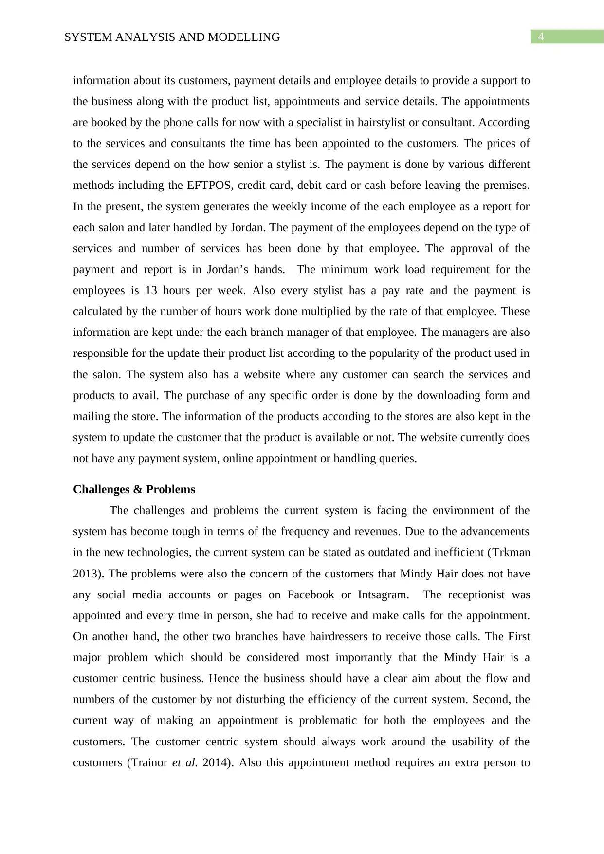
information about its customers, payment details and employee details to provide a support to
the business along with the product list, appointments and service details. The appointments
are booked by the phone calls for now with a specialist in hairstylist or consultant. According
to the services and consultants the time has been appointed to the customers. The prices of
the services depend on the how senior a stylist is. The payment is done by various different
methods including the EFTPOS, credit card, debit card or cash before leaving the premises.
In the present, the system generates the weekly income of the each employee as a report for
each salon and later handled by Jordan. The payment of the employees depend on the type of
services and number of services has been done by that employee. The approval of the
payment and report is in Jordan’s hands. The minimum work load requirement for the
employees is 13 hours per week. Also every stylist has a pay rate and the payment is
calculated by the number of hours work done multiplied by the rate of that employee. These
information are kept under the each branch manager of that employee. The managers are also
responsible for the update their product list according to the popularity of the product used in
the salon. The system also has a website where any customer can search the services and
products to avail. The purchase of any specific order is done by the downloading form and
mailing the store. The information of the products according to the stores are also kept in the
system to update the customer that the product is available or not. The website currently does
not have any payment system, online appointment or handling queries.
Challenges & Problems
The challenges and problems the current system is facing the environment of the
system has become tough in terms of the frequency and revenues. Due to the advancements
in the new technologies, the current system can be stated as outdated and inefficient (Trkman
2013). The problems were also the concern of the customers that Mindy Hair does not have
any social media accounts or pages on Facebook or Intsagram. The receptionist was
appointed and every time in person, she had to receive and make calls for the appointment.
On another hand, the other two branches have hairdressers to receive those calls. The First
major problem which should be considered most importantly that the Mindy Hair is a
customer centric business. Hence the business should have a clear aim about the flow and
numbers of the customer by not disturbing the efficiency of the current system. Second, the
current way of making an appointment is problematic for both the employees and the
customers. The customer centric system should always work around the usability of the
customers (Trainor et al. 2014). Also this appointment method requires an extra person to
5SYSTEM ANALYSIS AND MODELLING
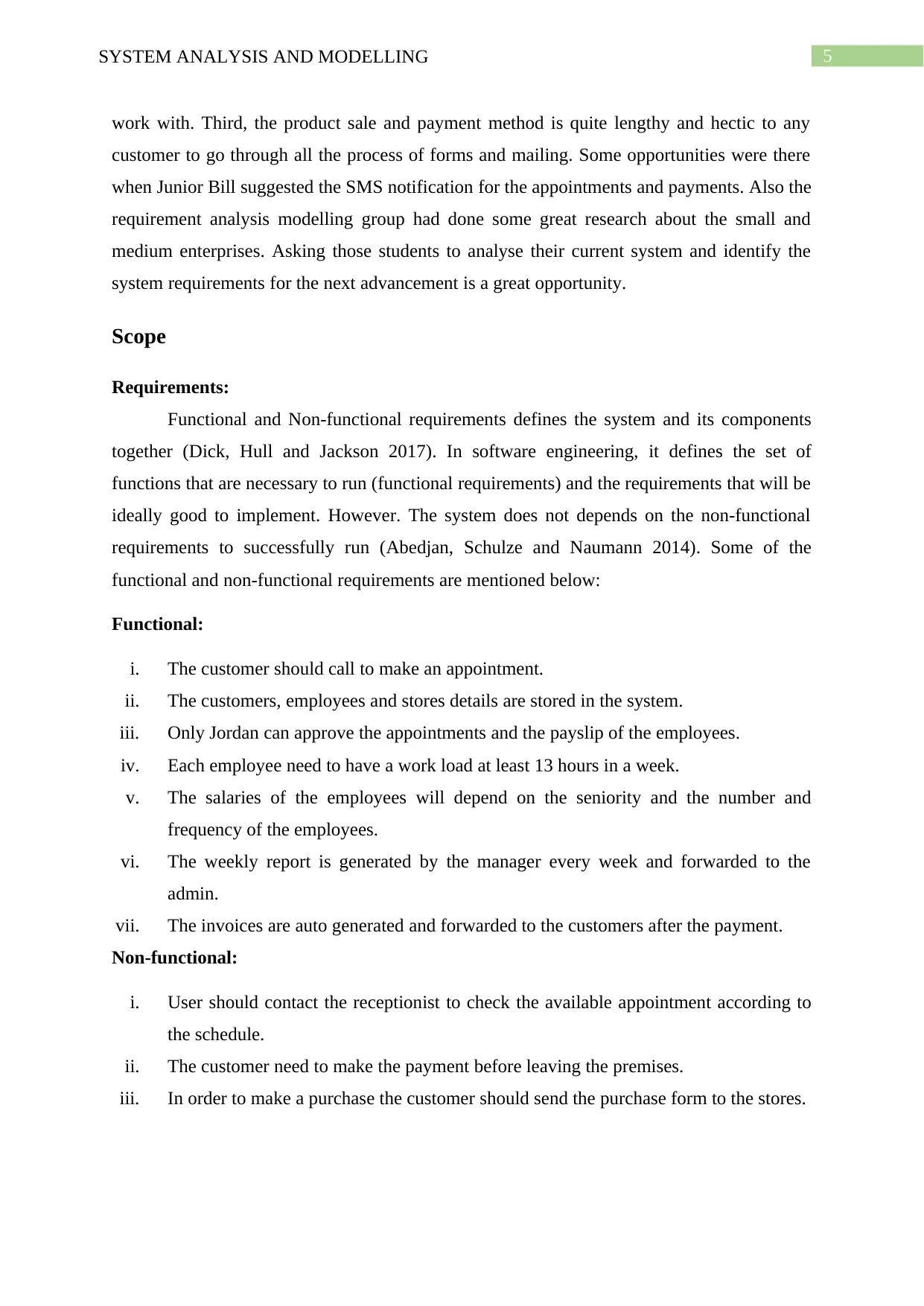
work with. Third, the product sale and payment method is quite lengthy and hectic to any
customer to go through all the process of forms and mailing. Some opportunities were there
when Junior Bill suggested the SMS notification for the appointments and payments. Also the
requirement analysis modelling group had done some great research about the small and
medium enterprises. Asking those students to analyse their current system and identify the
system requirements for the next advancement is a great opportunity.
Scope
Requirements:
Functional and Non-functional requirements defines the system and its components
together (Dick, Hull and Jackson 2017). In software engineering, it defines the set of
functions that are necessary to run (functional requirements) and the requirements that will be
ideally good to implement. However. The system does not depends on the non-functional
requirements to successfully run (Abedjan, Schulze and Naumann 2014). Some of the
functional and non-functional requirements are mentioned below:
Functional:
i. The customer should call to make an appointment.
ii. The customers, employees and stores details are stored in the system.
iii. Only Jordan can approve the appointments and the payslip of the employees.
iv. Each employee need to have a work load at least 13 hours in a week.
v. The salaries of the employees will depend on the seniority and the number and
frequency of the employees.
vi. The weekly report is generated by the manager every week and forwarded to the
admin.
vii. The invoices are auto generated and forwarded to the customers after the payment.
Non-functional:
i. User should contact the receptionist to check the available appointment according to
the schedule.
ii. The customer need to make the payment before leaving the premises.
iii. In order to make a purchase the customer should send the purchase form to the stores.
⊘ This is a preview!⊘
Do you want full access?
Subscribe today to unlock all pages.
Trusted by 1+ million students worldwide
6SYSTEM ANALYSIS AND MODELLING
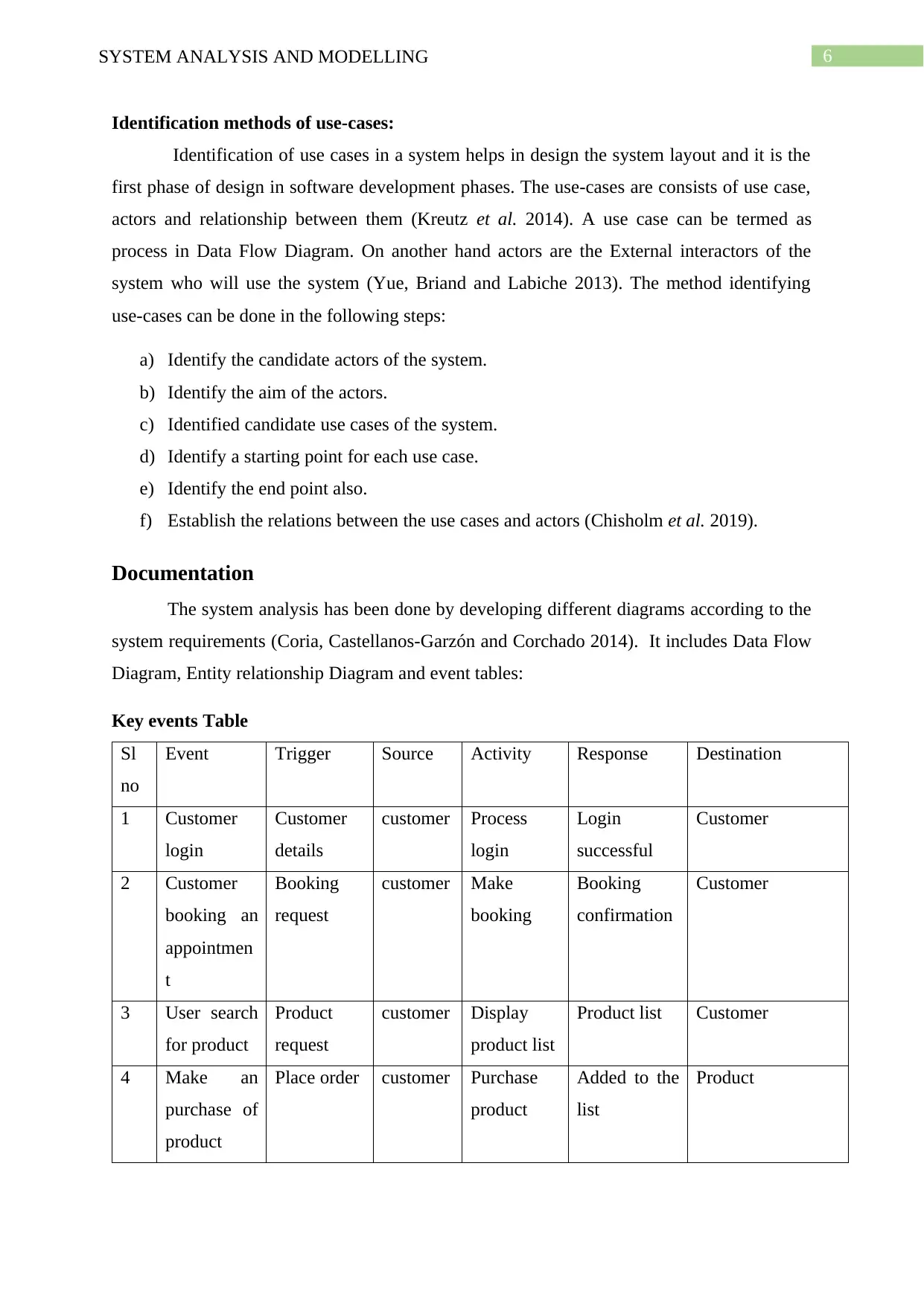
Identification methods of use-cases:
Identification of use cases in a system helps in design the system layout and it is the
first phase of design in software development phases. The use-cases are consists of use case,
actors and relationship between them (Kreutz et al. 2014). A use case can be termed as
process in Data Flow Diagram. On another hand actors are the External interactors of the
system who will use the system (Yue, Briand and Labiche 2013). The method identifying
use-cases can be done in the following steps:
a) Identify the candidate actors of the system.
b) Identify the aim of the actors.
c) Identified candidate use cases of the system.
d) Identify a starting point for each use case.
e) Identify the end point also.
f) Establish the relations between the use cases and actors (Chisholm et al. 2019).
Documentation
The system analysis has been done by developing different diagrams according to the
system requirements (Coria, Castellanos-Garzón and Corchado 2014). It includes Data Flow
Diagram, Entity relationship Diagram and event tables:
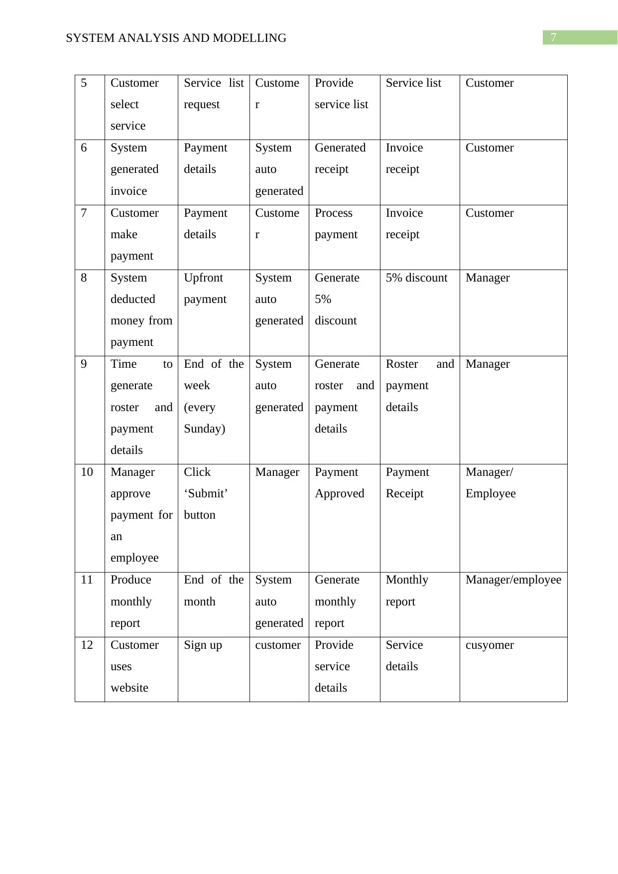
Key events Table
Sl
no
Event Trigger Source Activity Response Destination
1 Customer
login
Customer
details
customer Process
login
Login
successful
Customer
2 Customer
booking an
appointmen
t
Booking
request
customer Make
booking
Booking
confirmation
Customer
3 User search
for product
Product
request
customer Display
product list
Product list Customer
4 Make an
purchase of
product
Place order customer Purchase
product
Added to the
list
Product
Identification methods of use-cases:
Identification of use cases in a system helps in design the system layout and it is the
first phase of design in software development phases. The use-cases are consists of use case,
actors and relationship between them (Kreutz et al. 2014). A use case can be termed as
process in Data Flow Diagram. On another hand actors are the External interactors of the
system who will use the system (Yue, Briand and Labiche 2013). The method identifying
use-cases can be done in the following steps:
a) Identify the candidate actors of the system.
b) Identify the aim of the actors.
c) Identified candidate use cases of the system.
d) Identify a starting point for each use case.
e) Identify the end point also.
f) Establish the relations between the use cases and actors (Chisholm et al. 2019).
Documentation
The system analysis has been done by developing different diagrams according to the
system requirements (Coria, Castellanos-Garzón and Corchado 2014). It includes Data Flow
Diagram, Entity relationship Diagram and event tables:
Key events Table
Sl
no
Event Trigger Source Activity Response Destination
1 Customer
login
Customer
details
customer Process
login
Login
successful
Customer
2 Customer
booking an
appointmen
t
Booking
request
customer Make
booking
Booking
confirmation
Customer
3 User search
for product
Product
request
customer Display
product list
Product list Customer
4 Make an
purchase of
product
Place order customer Purchase
product
Added to the
list
Product
Paraphrase This Document
Need a fresh take? Get an instant paraphrase of this document with our AI Paraphraser
7SYSTEM ANALYSIS AND MODELLING
5 Customer
select
service
Service list
request
Custome
r
Provide
service list
Service list Customer
6 System
generated
invoice
Payment
details
System
auto
generated
Generated
receipt
Invoice
receipt
Customer
7 Customer
make
payment
Payment
details
Custome
r
Process
payment
Invoice
receipt
Customer
8 System
deducted
money from
payment
Upfront
payment
System
auto
generated
Generate
5%
discount
5% discount Manager
9 Time to
generate
roster and
payment
details
End of the
week
(every
Sunday)
System
auto
generated
Generate
roster and
payment
details
Roster and
payment
details
Manager
10 Manager
approve
payment for
an
employee
Click
‘Submit’
button
Manager Payment
Approved
Payment
Receipt
Manager/
Employee
11 Produce
monthly
report
End of the
month
System
auto
generated
Generate
monthly
report
Monthly
report
Manager/employee
12 Customer
uses
website
Sign up customer Provide
service
details
Service
details
cusyomer
8SYSTEM ANALYSIS AND MODELLING
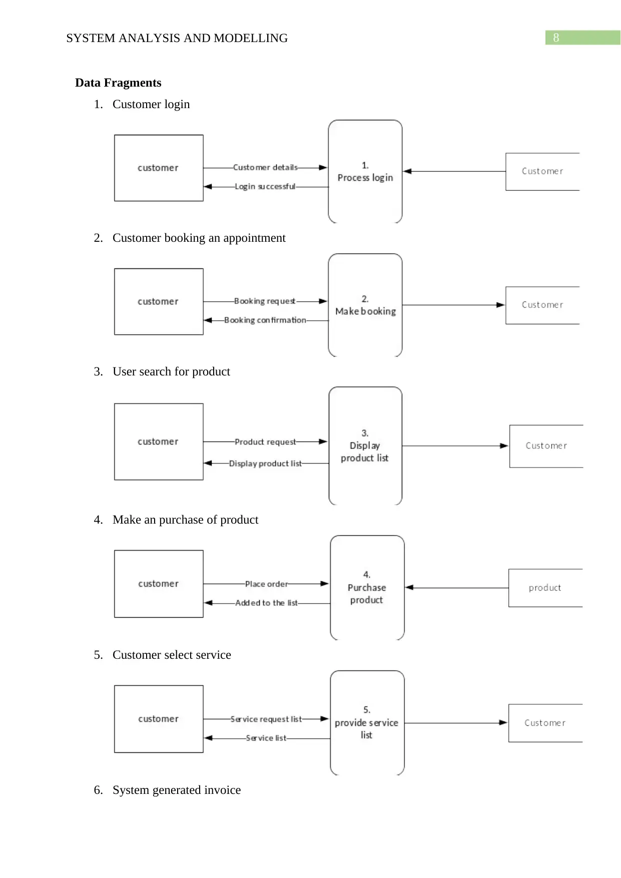
Data Fragments
1. Customer login
2. Customer booking an appointment
3. User search for product
4. Make an purchase of product
5. Customer select service
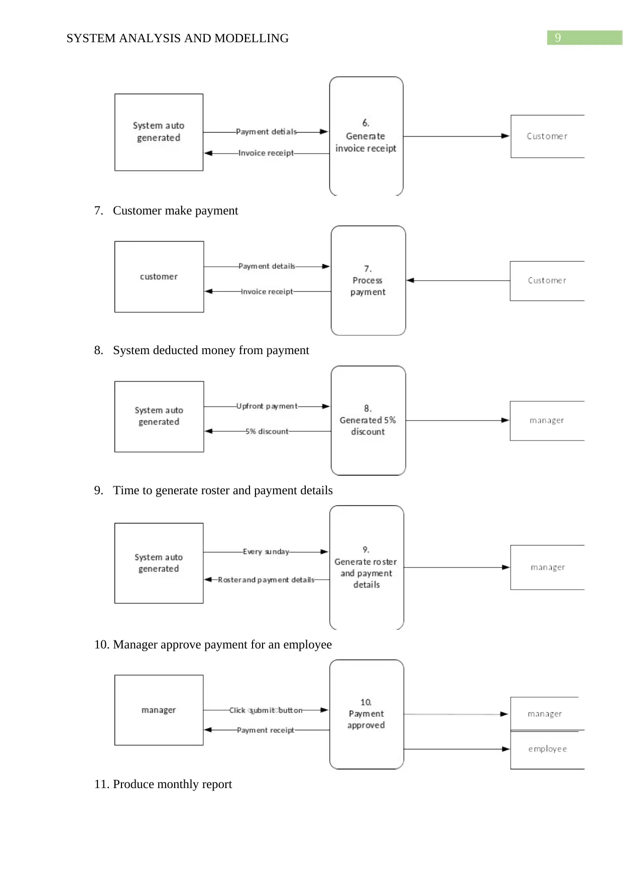
6. System generated invoice
Data Fragments
1. Customer login
2. Customer booking an appointment
3. User search for product
4. Make an purchase of product
5. Customer select service
6. System generated invoice
⊘ This is a preview!⊘
Do you want full access?
Subscribe today to unlock all pages.
Trusted by 1+ million students worldwide
9SYSTEM ANALYSIS AND MODELLING
7. Customer make payment
8. System deducted money from payment
9. Time to generate roster and payment details
10. Manager approve payment for an employee
11. Produce monthly report
7. Customer make payment
8. System deducted money from payment
9. Time to generate roster and payment details
10. Manager approve payment for an employee
11. Produce monthly report
Paraphrase This Document
Need a fresh take? Get an instant paraphrase of this document with our AI Paraphraser
10SYSTEM ANALYSIS AND MODELLING
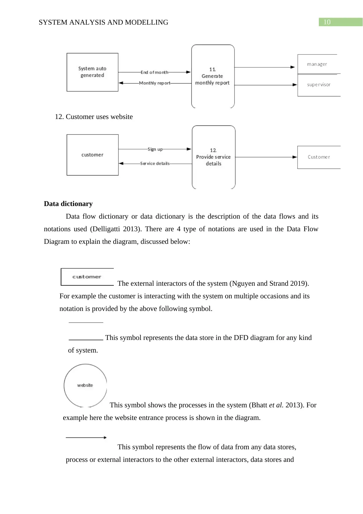
12. Customer uses website
Data dictionary
Data flow dictionary or data dictionary is the description of the data flows and its
notations used (Delligatti 2013). There are 4 type of notations are used in the Data Flow
Diagram to explain the diagram, discussed below:
The external interactors of the system (Nguyen and Strand 2019).
For example the customer is interacting with the system on multiple occasions and its
notation is provided by the above following symbol.
This symbol represents the data store in the DFD diagram for any kind
of system.
This symbol shows the processes in the system (Bhatt et al. 2013). For
example here the website entrance process is shown in the diagram.
This symbol represents the flow of data from any data stores,
process or external interactors to the other external interactors, data stores and
11SYSTEM ANALYSIS AND MODELLING
processes (Adams et al. 2014).
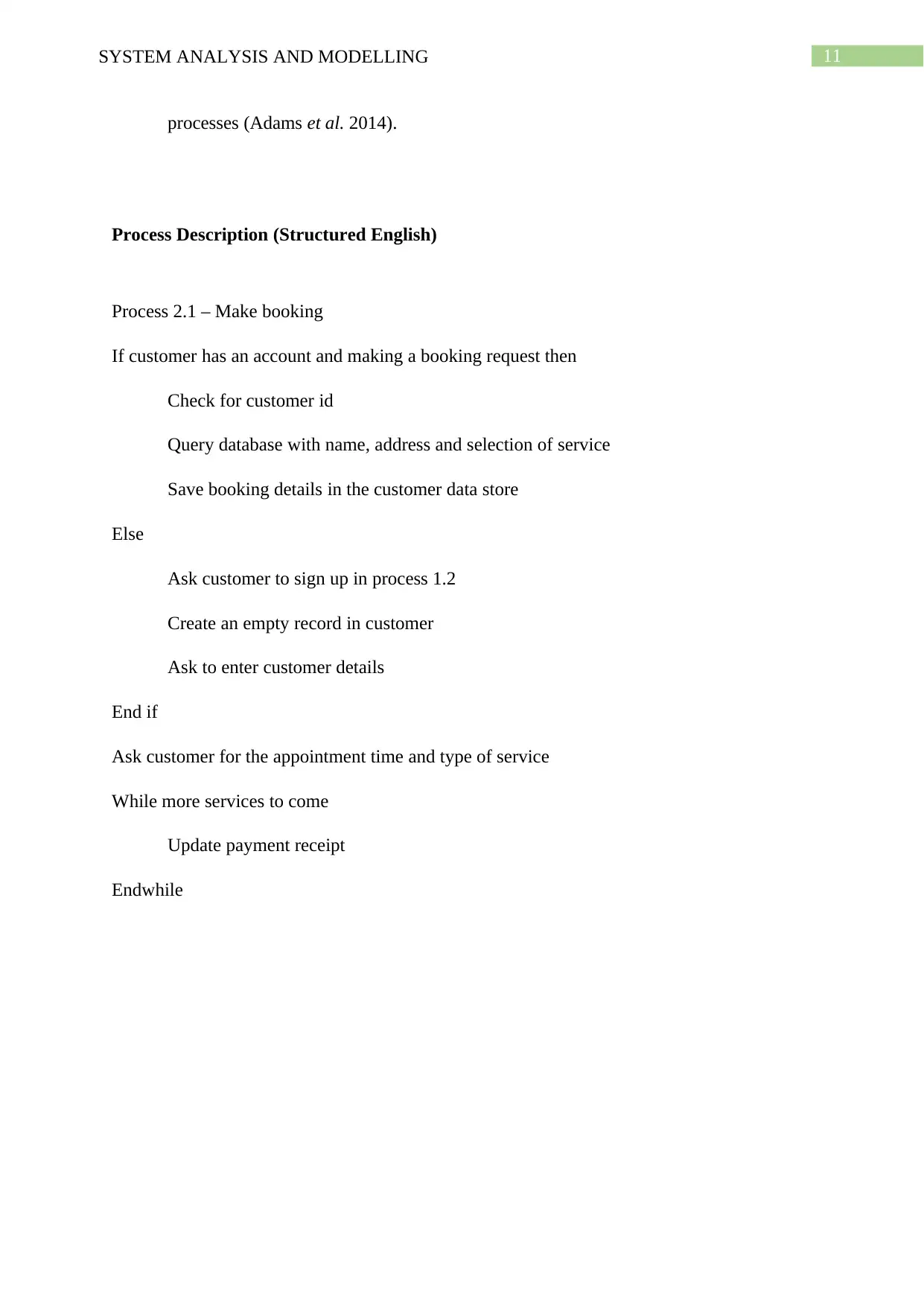
Process Description (Structured English)
Process 2.1 – Make booking
If customer has an account and making a booking request then
Check for customer id
Query database with name, address and selection of service
Save booking details in the customer data store
Else
Ask customer to sign up in process 1.2
Create an empty record in customer
Ask to enter customer details
End if
Ask customer for the appointment time and type of service
While more services to come
Update payment receipt
Endwhile
processes (Adams et al. 2014).
Process Description (Structured English)
Process 2.1 – Make booking
If customer has an account and making a booking request then
Check for customer id
Query database with name, address and selection of service
Save booking details in the customer data store
Else
Ask customer to sign up in process 1.2
Create an empty record in customer
Ask to enter customer details
End if
Ask customer for the appointment time and type of service
While more services to come
Update payment receipt
Endwhile
⊘ This is a preview!⊘
Do you want full access?
Subscribe today to unlock all pages.
Trusted by 1+ million students worldwide
1 out of 21
Related Documents


Your All-in-One AI-Powered Toolkit for Academic Success.
+13062052269
info@desklib.com
Available 24*7 on WhatsApp / Email
![[object Object]](/_next/static/media/star-bottom.7253800d.svg)
Unlock your academic potential
Copyright © 2020–2026 A2Z Services. All Rights Reserved. Developed and managed by ZUCOL.