IMAT5205 - System Analysis & Design: Wide World Tour Use Case
VerifiedAdded on 2023/04/20
|11
|2248
|378
Report
AI Summary
This report presents a system analysis and design for the 'Record New Tour' use case within the Wide World Tour Management system. It includes an analysis class diagram detailing the relationships between classes such as Tour, Guide, Driver, and Clerical, along with their attributes and operations. A communication diagram illustrates the interactions between entities, emphasizing message passing and object relationships. Furthermore, a sequence diagram visualizes the flow of messages between objects, highlighting the role of the Assistant in managing tour details and driver assignments. The report also evaluates the use of CASE tools in the development process, emphasizing their benefits in terms of time and cost reduction, requirement tracking, and system consistency. Object-oriented analysis and design concepts are discussed, underscoring their importance in identifying objects, relationships, and converting designs into executable code.

Running head: SYSTEM ANALYSIS AND DESIGN
SYSTEM ANALYSIS AND DESIGN
Name of the Student
Name of the University
Author Note
SYSTEM ANALYSIS AND DESIGN
Name of the Student
Name of the University
Author Note
Paraphrase This Document
Need a fresh take? Get an instant paraphrase of this document with our AI Paraphraser
1SYSTEM ANALYSIS AND DESIGN
Table of Contents
Part1: Use Case Realisation for the Record New Tour Use Case..........................................................2
Analysis class diagram......................................................................................................................2
Communication Diagram...................................................................................................................3
PART2: Sequence Diagram...................................................................................................................4
Part 3: Evaluation..................................................................................................................................6
Bibliography..........................................................................................................................................8
2SYSTEM ANALYSIS AND DESIGN
Part1: Use Case Realisation for the Record New Tour Use Case
Analysis class diagram
a. With the analysis class diagram the concepts rleated to the problems within the system can be
assessed diretly. UML class diagrams are used to view the classes within the system. Tthis
helps in depicting the inter relationships , attributes related to each class and the operaations
performed by this classes. The requirmenets are analysed based on a conceptual model. class
diagrrams are refred to as the blueprints of the system. With the use of class diagram user can
model objects that are used within a system. This helps in depicting the relationships between
the objects and also helps in describing the services offered by the objects. The importance of
using a class digarma is that it helps in modleing off object oriendted system because this are
the only system of UML that allows mapping with object oriented languaes.
b.
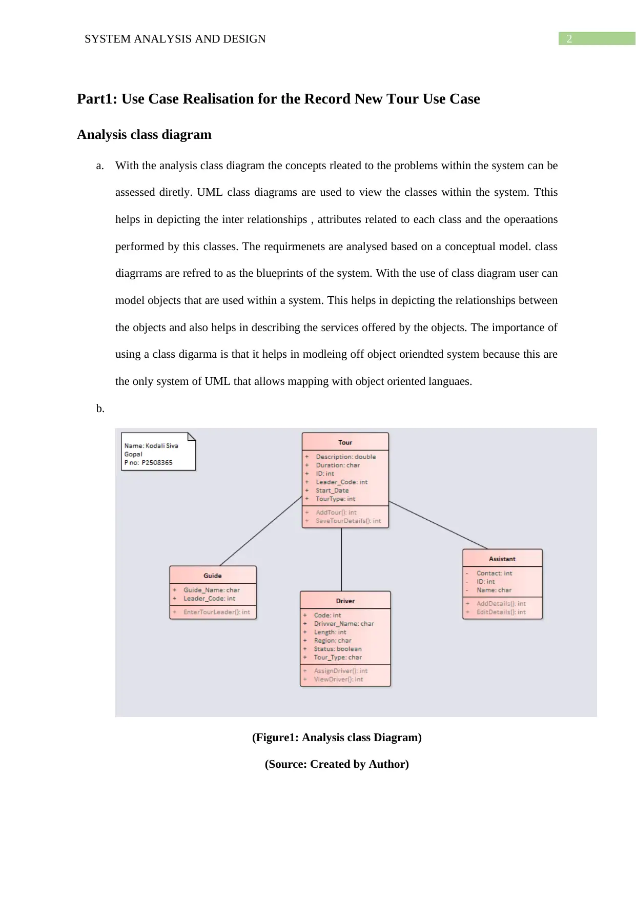
(Figure1: Analysis class Diagram)
(Source: Created by Author)
Part1: Use Case Realisation for the Record New Tour Use Case
Analysis class diagram
a. With the analysis class diagram the concepts rleated to the problems within the system can be
assessed diretly. UML class diagrams are used to view the classes within the system. Tthis
helps in depicting the inter relationships , attributes related to each class and the operaations
performed by this classes. The requirmenets are analysed based on a conceptual model. class
diagrrams are refred to as the blueprints of the system. With the use of class diagram user can
model objects that are used within a system. This helps in depicting the relationships between
the objects and also helps in describing the services offered by the objects. The importance of
using a class digarma is that it helps in modleing off object oriendted system because this are
the only system of UML that allows mapping with object oriented languaes.
b.
(Figure1: Analysis class Diagram)
(Source: Created by Author)
⊘ This is a preview!⊘
Do you want full access?
Subscribe today to unlock all pages.
Trusted by 1+ million students worldwide
3SYSTEM ANALYSIS AND DESIGN
c. The above developed diagram is an analysis class diagram for “Record New Tour”. The
digaram is dveeloped with the use of Use Case. The dveloped system includes every type of
important entity classes along with all te attributes. The major classes described in the
analysis diagram are Tour, Guide , Driver and Clercial. Every class defined in the system
contains some entities. Tour class is having the netities Description, Durattion , ID ,
Leader_Code,Start_Date and TourType. The two operations within this class are AddTour()
and SaveTourDetails(). Driver class contains attributes Code, Driver_Name, Length, Region,
Tour_Type and Status. The attributes of this class are AssignDriver() and View Driver(). One
of the most im portant class of analysis class diagram is Guide with attributes Guide_Name
and Leader_Code and one opertaaion EnterTourLeader. The assistant class contains details
about the clerical assistant with their name and ID. This allows the class to AddDeatils()
whenevr needed and EditDetails(). Once the dirver class finds any dirver it assigns the dirver
to the new tour and allocates all the details regarding to the drivers.
Communication Diagram
a. The main concept of Unified modelling language is that it allows the user to use different
types of diagrams for various purposes. In order to have a proper static nature of the system-
developed class diagrams are used, sequence diagrams are developed with the use of
sequential logic and with the use of state machine diagram one can determine the complex
classes and the behaviour of this model. Communication diagram is an interaction diagram
that is used to focus entirely on the object relationships. In this diagram, objects are viewed in
association with the connectors between them. The purpose of communication diagram is that
it helps passing the messages between objects. This also supports the identification of objects
and the attributes associated with them.
Paraphrase This Document
Need a fresh take? Get an instant paraphrase of this document with our AI Paraphraser
4SYSTEM ANALYSIS AND DESIGN
b.
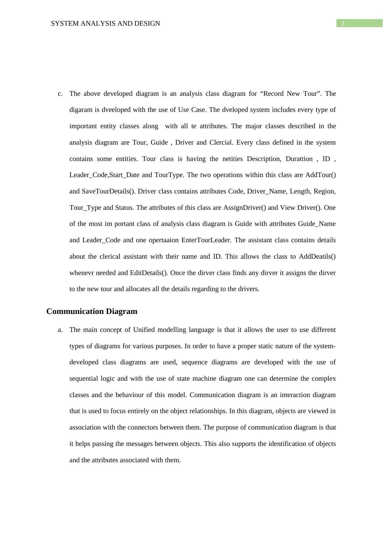
(Figure2: Communication Diagram)
(Source: Created by Author)
c. Communication diagram is used for proper communication between the entities. The main
actor in this system is Assistant. Assistant is responsible for assigning details regarding the
tour. The classes in involved in this system are Guide_Details , Tour_Details and
Driver_Details. The World Wide Tour Management needs a proper communication diagram
for further operations on tour. With the use of ViewDriverDetals(). With the help of
AddTour() , the assistant can start a new tour. It is important to include tour details so that the
guide can have a clear information about the tour. Once the assistant interacts with the objects
present within the system, the details at every step gets stored. These details will be saved
automatically within system and the details can be viewed at any time. Each class stores
details regarding their class and allows connecting these details with tour classes.
b.
(Figure2: Communication Diagram)
(Source: Created by Author)
c. Communication diagram is used for proper communication between the entities. The main
actor in this system is Assistant. Assistant is responsible for assigning details regarding the
tour. The classes in involved in this system are Guide_Details , Tour_Details and
Driver_Details. The World Wide Tour Management needs a proper communication diagram
for further operations on tour. With the use of ViewDriverDetals(). With the help of
AddTour() , the assistant can start a new tour. It is important to include tour details so that the
guide can have a clear information about the tour. Once the assistant interacts with the objects
present within the system, the details at every step gets stored. These details will be saved
automatically within system and the details can be viewed at any time. Each class stores
details regarding their class and allows connecting these details with tour classes.
5SYSTEM ANALYSIS AND DESIGN
PART2: Sequence Diagram
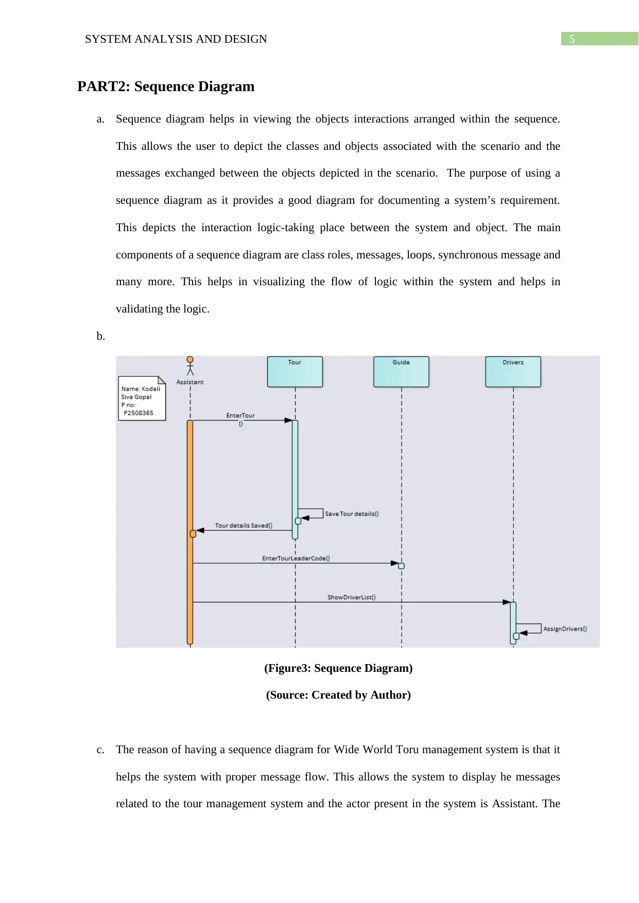
a. Sequence diagram helps in viewing the objects interactions arranged within the sequence.
This allows the user to depict the classes and objects associated with the scenario and the
messages exchanged between the objects depicted in the scenario. The purpose of using a
sequence diagram as it provides a good diagram for documenting a system’s requirement.
This depicts the interaction logic-taking place between the system and object. The main
components of a sequence diagram are class roles, messages, loops, synchronous message and
many more. This helps in visualizing the flow of logic within the system and helps in
validating the logic.
b.
(Figure3: Sequence Diagram)
(Source: Created by Author)
c. The reason of having a sequence diagram for Wide World Toru management system is that it
helps the system with proper message flow. This allows the system to display he messages
related to the tour management system and the actor present in the system is Assistant. The
PART2: Sequence Diagram
a. Sequence diagram helps in viewing the objects interactions arranged within the sequence.
This allows the user to depict the classes and objects associated with the scenario and the
messages exchanged between the objects depicted in the scenario. The purpose of using a
sequence diagram as it provides a good diagram for documenting a system’s requirement.
This depicts the interaction logic-taking place between the system and object. The main
components of a sequence diagram are class roles, messages, loops, synchronous message and
many more. This helps in visualizing the flow of logic within the system and helps in
validating the logic.
b.
(Figure3: Sequence Diagram)
(Source: Created by Author)
c. The reason of having a sequence diagram for Wide World Toru management system is that it
helps the system with proper message flow. This allows the system to display he messages
related to the tour management system and the actor present in the system is Assistant. The
⊘ This is a preview!⊘
Do you want full access?
Subscribe today to unlock all pages.
Trusted by 1+ million students worldwide
6SYSTEM ANALYSIS AND DESIGN
assistant is responsible for interaction taking place within the system and focuses on the
messages delivered from one class to another. The main role of this assistant is to adding the
tour in the system and allows the system to view the driver list. The assistant has the ability to
assign drivers and share the details. Once a driver is found free, it is allocated to the Tour. In
the diver details, every useful information are being registered this will help the customer
throughout their tour.
Part 3: Evaluation
CASE tools offers a wide range of tools for designing and implementation of applications.
Enterprise architecture used for Wide World Tour Management System. With the use of
enterprise architecture system the messages can be displayed along with the other elements
related to the tour. CASE tools are referred to as the domain of software tools and allows design
and implementation with the use of tools. Three different categories are supported with CASE
tools. These three categories includes:
Tools that are used for providing a support towards the software life cycle
Workbenches are combined with more than one tools and focuses on the specific part of
the system
The whole life cycle can be supported with proper environment and workbenches.
The tools offered by the CASE allows some specific tasks to perform at the time of software
development cycle. These tasks are divided further into six categories. These are business and
analysis modelling, validation and verification, development, measurements and metrics, project
management and configuration management. With the use of Computer Aided Software Engineering
technologies tools, the user can develop a better system with efficient infrastructure. The main benefit
of using CASE tolls is that it helps in minimizing the time and cost needed the system to be
developed. The system is being developed after analysing the requirements of organization. Apart
from this other benefits offered by Computer Aided Software Engineering technologies helps system
analyst in developing a system. The benefits are CASE tools allows the developer to track all the
Paraphrase This Document
Need a fresh take? Get an instant paraphrase of this document with our AI Paraphraser
7SYSTEM ANALYSIS AND DESIGN
requirements needed for the system at the development stage. With the help of CASE tools, the
developer are allowed to perform system layering and provides a data dictionary for the system. The
syntax can be checked with the system of CASE tools and allows the system to maintain a consistency
and completeness. The problems faced while developing the systems can be aided with the use of
CASE tool. The systems performance can also be determined with the use of Computer Aided
Software Engineering technologies tools.
With the use of CASE tools system analyst can improve their working. The main aim of
CASE tools is that it provides a better support while developing a process within a system. In the
integration time, it provides a better support towards the developing system. This facilitates the
developer to display the system in front of the customers. Analyst will always aim at using a software
that provides smooth analysis tools. With the use of this tool, analyst will be able to enhance the
functions in system and helps in utilizing the functions effectively for improved results. The main
reason of using CASE tools while developing the system for tour management system is that it will
improve the functionality from every aspect of the system.
Several different ways are there for improving the efficiency of working done by the analyst.
There are knowledge’s that helps the analyst to develop a system according to the requirement. With
the use of CASE tools, the activities related to programming and data designing are aided. Moreover,
the system allows having more than one developer for performing different activities. This will help
in reducing workload. Before developing a system, the developer needs to be aware about the systems
feasibility. Proper maintenance can be provided once a system is being developed properly. It is
important to have a proper staff. With proper staffs, the system can be developed even more quickly
and effectively. Self-earning capability of every staff will improve their working skills and will help
in growth. Thus, it becomes an important factor to understand the importance of object oriented
analysis and designing concepts. The purpose of having an analyst and a developer is that, they help
in identifying the objects associated with a system. This helps in identifying the relationships
maintained between each object and each entity. This also helps the developer by converting a design
to an executable one with the help of object oriented language. Once the analysis is done, then the

8SYSTEM ANALYSIS AND DESIGN
contents are used as input for UML diagrams and OO. The input for OO analysis and design are
further used as input to the UML diagrams.
contents are used as input for UML diagrams and OO. The input for OO analysis and design are
further used as input to the UML diagrams.
⊘ This is a preview!⊘
Do you want full access?
Subscribe today to unlock all pages.
Trusted by 1+ million students worldwide

9SYSTEM ANALYSIS AND DESIGN
Bibliography
Dennis, A., Wixom, B.H. and Tegarden, D., 2015. Systems analysis and design: An object-oriented
approach with UML. John wiley & sons.
Gill, A.Q., 2015. Agile enterprise architecture modelling: Evaluating the applicability and integration
of six modelling standards. Information and Software Technology, 67, pp.196-206.
Karim, S., Liawatimena, S., Trisetyarso, A., Abbas, B.S. and Suparta, W., 2017, November.
Automating functional and structural software size measurement based on XML structure of UML
sequence diagram. In Cybernetics and Computational Intelligence (CyberneticsCom), 2017 IEEE
International Conference on (pp. 24-28). IEEE.
Marcinkowski, B. and Wrycza, S., 2015. CASE tools’ acceptance in higher education–Assessment
and enhanced UTAUT model. In Proceedings of the Conference on Information Systems Applied
Research ISSN (Vol. 2167, p. 1508).
Martin, J. and Odell, J.J., 2014. Object-oriented methods. Prentice hall PTR.
Niemi, E. and Pekkola, S., 2017. Using enterprise architecture artefacts in an organisation. Enterprise
Information Systems, 11(3), pp.313-338.
Nikpay, F., Ahmad, R., Rouhani, B.D. and Shamshirband, S., 2016. A systematic review on post-
implementation evaluation models of enterprise architecture artefacts. Information Systems Frontiers,
pp.1-20.
Rumbaugh, J., Booch, G. and Jacobson, I., 2017. The unified modeling language reference manual.
Addison Wesley.
Samuel, P., Mall, R. and Bothra, A.K., 2008. Automatic test case generation using unified modeling
language (UML) state diagrams. IET software, 2(2), pp.79-93.
Shen, H., Krishnan, R., Slavin, R. and Niu, J., 2016. Sequence Diagram Aided Privacy Policy
Specification. IEEE Transactions on Dependable and Secure Computing, 13(3), pp.381-393.
Paraphrase This Document
Need a fresh take? Get an instant paraphrase of this document with our AI Paraphraser

10SYSTEM ANALYSIS AND DESIGN
Ye, T., Dai, N., Lam, C.S., Wong, M.C. and Guerrero, J.M., 2016. Analysis, design, and
implementation of a quasi-proportional-resonant controller for a multifunctional capacitive-coupling
grid-connected inverter. IEEE Transactions on Industry Applications, 52(5), pp.4269-4280.
Ye, T., Dai, N., Lam, C.S., Wong, M.C. and Guerrero, J.M., 2016. Analysis, design, and
implementation of a quasi-proportional-resonant controller for a multifunctional capacitive-coupling
grid-connected inverter. IEEE Transactions on Industry Applications, 52(5), pp.4269-4280.
1 out of 11
Related Documents


Your All-in-One AI-Powered Toolkit for Academic Success.
+13062052269
info@desklib.com
Available 24*7 on WhatsApp / Email
![[object Object]](/_next/static/media/star-bottom.7253800d.svg)
Unlock your academic potential
Copyright © 2020–2026 A2Z Services. All Rights Reserved. Developed and managed by ZUCOL.