ISY00243: System Analysis and Design Report for Natural Lee Company
VerifiedAdded on 2022/08/19
|20
|4086
|11
Report
AI Summary
This report presents a System Analysis and Design solution for Natural Lee Company, a business producing organic produce. The report encompasses various activities including fact-finding through documentation and interviews with staff, use case analysis to define system interactions, and the creation of an Entity Relationship Diagram (ERD) and Domain Class Diagrams to model the database structure and system classes. Furthermore, the report includes System Sequence Diagrams to illustrate system interactions and Project Management Charts tracking progress against tasks. The goal is to guide the fictional client in selecting the appropriate computer application for the business. The assignment covers several aspects of system analysis and design to ensure a comprehensive understanding of the business requirements and a well-structured system design.

Running head: SYSTEM ANALYSIS AND DESIGN
SYSTEM ANALYSIS AND DESIGN
Name of the Student:
Name of the University:
Author Note:
SYSTEM ANALYSIS AND DESIGN
Name of the Student:
Name of the University:
Author Note:
Paraphrase This Document
Need a fresh take? Get an instant paraphrase of this document with our AI Paraphraser
1SYSTEM ANALYSIS AND DESIGN
Executive summary:
The purpose of the paper is to make an information system for Natural Lee Company. Natural
Lee produces fruit, nuts, eggs, decorative plants and vegetables that are certified organically
and grown by biodynamic soils and permaculture principles. This started initially in backyard
of Kevin Lee. He along with his friends begun community garden and for increasing demand
of organic food that are locally grown, this has grown to commercial venture. The prospect of
the business expanded in last few year with Kevin’s return to property of his family which
historically was used as station of cattle grazing. Though this was main commitment, Kevin
turned much of land in to food forest. He worked tirelessly and they have now employed
agriculture and horticulture students from faculty of Plant Science form Southern Cross
University for assisting on property.
2SYSTEM ANALYSIS AND DESIGN
Table of Contents
Activity 5:...................................................................................................................................3
Fact Findings Documents.......................................................................................................3
Activity 6:...................................................................................................................................4
Use Cases...............................................................................................................................4
Activity 7:...................................................................................................................................6
ERD........................................................................................................................................6
Domain Class Diagrams.........................................................................................................9
Activity 8:.................................................................................................................................11
System Sequence Diagrams.................................................................................................11
Project Management Charts with progress against tasks.........................................................13
Conclusion and Recommendations..........................................................................................14
References................................................................................................................................16
⊘ This is a preview!⊘
Do you want full access?
Subscribe today to unlock all pages.
Trusted by 1+ million students worldwide
3SYSTEM ANALYSIS AND DESIGN
Activity 5:
Fact Findings Documents
Best way for analysing the system is collecting the facts from the documentation
instead of human sources. Several types of documents are there for collecting facts from the
documents. Sampling techniques are used for organizing the documentations such as
complaints of customer, emails, notes of suggestion box and the reports. Sampling technique
is process to combine sample of form, records and documents. Two most used sampling
techniques are stratification and randomization (Alston and Knuckey 2016). Stratification is
systematic process for deducting variance of the sampling data. Randomization is process to
select randomly the sample data. The system of this business could be understood better due
to analysis of the forms, files and documents that are related to current system.
Two of the staffs can be interviewed who are Conrad and Mike. The questions for the
employees are as per following:
1. Problems they are facing at their work.
2. What type of facilities need to provide to the staffs?
Requirement analysis could be said for identifying investigation, analysing and
documenting the system requirements of the business. The initial step for investigation for
need of system is major activity for analysis of the problem. It is role of system analyst for
determining actual requirement for the system (Dwivedi et al. 2015). System analyst
sometimes might make mistake to discover requirements and to try in analysing the problem.
As result, they might come with wrong solution for designing and implementing the solution.
And solution would not be able in solving rea issue as well as cause new issue in later
analysis process of the system. Fact finding documents is process to collect information and
data depending on the techniques that contain the sampling of the existing research,
Paraphrase This Document
Need a fresh take? Get an instant paraphrase of this document with our AI Paraphraser
4SYSTEM ANALYSIS AND DESIGN
documents, interviews, questionnaires, planning of joint requirements, prototyping and
observation. Suitable techniques of fact finding is used by the system analyst for developing
and implementing existing current system (King, Lam and Roberts 2017).
Questions for Conrad:
1. What benefit will come from implementing the information system?
2. Why customer feedback is important?
Questions for Mike:
1. Did you take any feedback from the customer?
2. What are the problems that you have faced?
Collecting the needed facts are really important to apply the tools within life cycle of
the system development without appropriate extracting from the facts. Techniques of fact
finding are used within early stage of system development life cycle which includes phase of
system analysis, design and review of post implementation. Facts which are included within
information system could be tested depending on the three steps: process where the functions
are used for performing objectives, data where the facts are used for creating useful
information and interface which is designed for interacting with the users (Matsuura and
Schenk, 2017).
Activity 6:
Use Cases
Natural-Lee produces fruit, nuts, eggs, decorative plants and vegetables that are
organically certified which are grown by biodynamic soils and permaculture principles. This
started initially in backyard of Kevin Lee. It is believed by Kevin that he had born to be on
5SYSTEM ANALYSIS AND DESIGN
land, thus he had done, in his family’s step with their passion and love for living green and
sustainably. Kevin now has dedicated passionately in growing produce instead of attending
for the cattle and sheep. He has few cows for manure as well as milk and acquired chickens
recently for providing separate manure for fertilization along with to production of egg. He
grew organic produce greatly without using any artificial fertiliser or pesticides. He practiced
planting of companion for helping protect the crops from the attacks of the insects as well as
he cycled separate crops per year for aiding health of soil. In system engineering, use case is
list of event steps or actions, which typically define interaction among a system and a role for
achieving the goal.
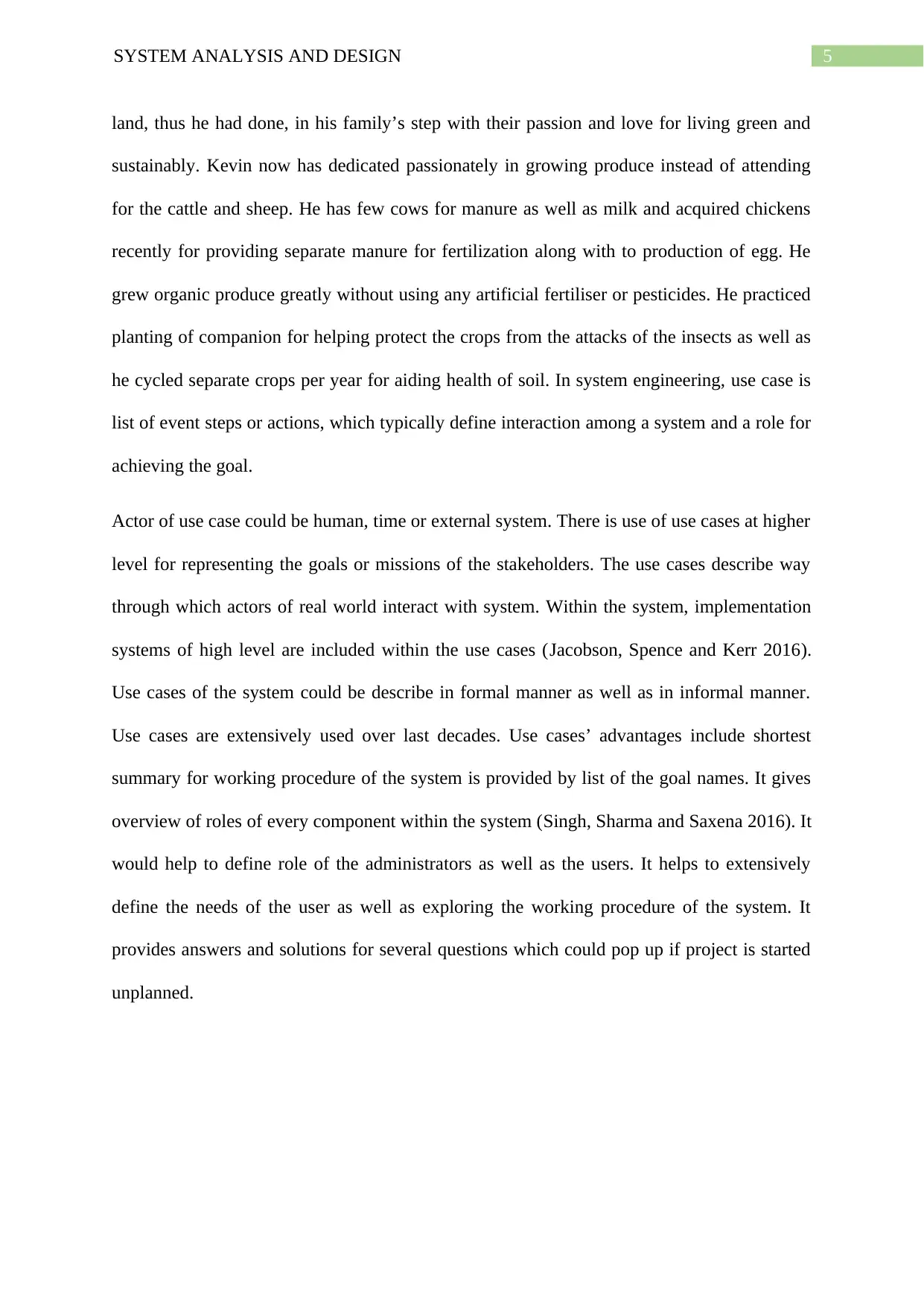
Actor of use case could be human, time or external system. There is use of use cases at higher
level for representing the goals or missions of the stakeholders. The use cases describe way
through which actors of real world interact with system. Within the system, implementation
systems of high level are included within the use cases (Jacobson, Spence and Kerr 2016).
Use cases of the system could be describe in formal manner as well as in informal manner.
Use cases are extensively used over last decades. Use cases’ advantages include shortest
summary for working procedure of the system is provided by list of the goal names. It gives
overview of roles of every component within the system (Singh, Sharma and Saxena 2016). It
would help to define role of the administrators as well as the users. It helps to extensively
define the needs of the user as well as exploring the working procedure of the system. It
provides answers and solutions for several questions which could pop up if project is started
unplanned.
land, thus he had done, in his family’s step with their passion and love for living green and
sustainably. Kevin now has dedicated passionately in growing produce instead of attending
for the cattle and sheep. He has few cows for manure as well as milk and acquired chickens
recently for providing separate manure for fertilization along with to production of egg. He
grew organic produce greatly without using any artificial fertiliser or pesticides. He practiced
planting of companion for helping protect the crops from the attacks of the insects as well as
he cycled separate crops per year for aiding health of soil. In system engineering, use case is
list of event steps or actions, which typically define interaction among a system and a role for
achieving the goal.
Actor of use case could be human, time or external system. There is use of use cases at higher
level for representing the goals or missions of the stakeholders. The use cases describe way
through which actors of real world interact with system. Within the system, implementation
systems of high level are included within the use cases (Jacobson, Spence and Kerr 2016).
Use cases of the system could be describe in formal manner as well as in informal manner.
Use cases are extensively used over last decades. Use cases’ advantages include shortest
summary for working procedure of the system is provided by list of the goal names. It gives
overview of roles of every component within the system (Singh, Sharma and Saxena 2016). It
would help to define role of the administrators as well as the users. It helps to extensively
define the needs of the user as well as exploring the working procedure of the system. It
provides answers and solutions for several questions which could pop up if project is started
unplanned.
⊘ This is a preview!⊘
Do you want full access?
Subscribe today to unlock all pages.
Trusted by 1+ million students worldwide
6SYSTEM ANALYSIS AND DESIGN
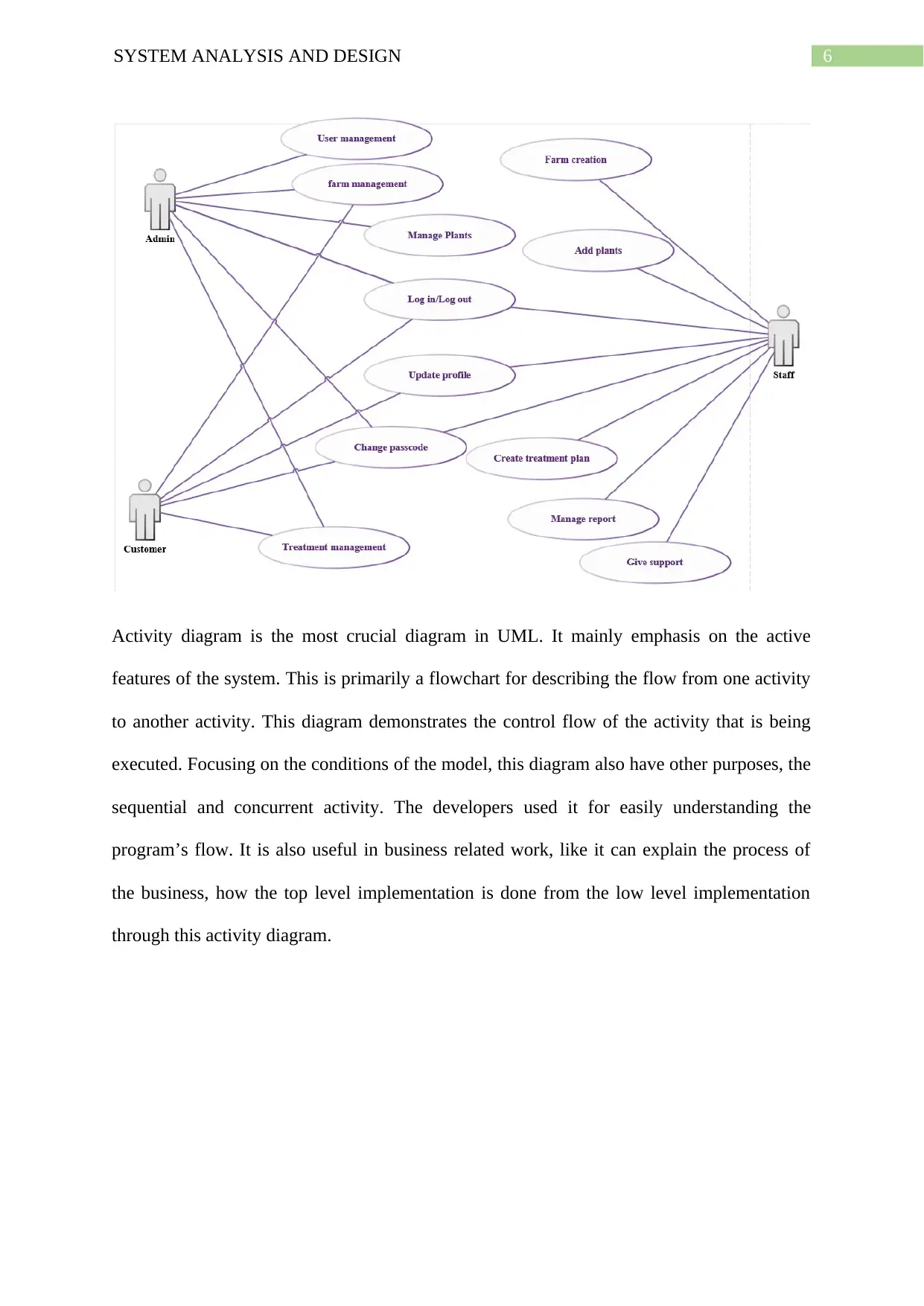
Activity diagram is the most crucial diagram in UML. It mainly emphasis on the active
features of the system. This is primarily a flowchart for describing the flow from one activity
to another activity. This diagram demonstrates the control flow of the activity that is being
executed. Focusing on the conditions of the model, this diagram also have other purposes, the
sequential and concurrent activity. The developers used it for easily understanding the
program’s flow. It is also useful in business related work, like it can explain the process of
the business, how the top level implementation is done from the low level implementation
through this activity diagram.
Paraphrase This Document
Need a fresh take? Get an instant paraphrase of this document with our AI Paraphraser
7SYSTEM ANALYSIS AND DESIGN
Use case within this system for the business provides the main objective of the
system. The primary actors within the system shows who would have access within the
system. The use case provides the scope of the system. Level of use case shows the level
where implementation of use case would be within the system (Jovic et al. 2016). Flow of use
case would be flow of the functionality which should be there. It provides the flow of work
for the system. Analysis of use case of the system is valuable and important technique of
requirement analysis which is used widely.
Activity 7:
ERD
Kevin Lee carried immense information inside his memory about seasons, weather,
types of soil, crop rotations, crops, composting and preparation of soil. With volume as well
as range of produce, as well as with outputs of animals, along with customers’ growing
number Kevin is having trouble in keeping track of the things. Information system might
provide way for managing the business’s increasing complexities (Laudon and Laudon 2015).
8SYSTEM ANALYSIS AND DESIGN
ERD can describe the things of interest that are interrelated as well as existed within specific
domain for knowledge. ER model is generated from the types of entities as well as specifies
the relationships which could exist between the entities. ERD is basically a structural diagram
which is utilized to design the database of the system. ERD have different connectors and
symbols which visualise two essential information: major entities in scope of the system as
well as inter-relationships between the entities (Al-Masree 2015). Entity relationship diagram
is a perceptible instrument which is used to constitute ER-model. It describes the entire
logical construction of database and it permits a person to convey on the logical construction
of the user interface. ERD diagram consists of the three elements that are entity, attributes
and relationship. It is composed of computers and people which interprets or processes
information. It is used sometimes in much more restricted sense for referring to only
computer system or for referring to only software that is used for running computerized
database. It is a system having complementary network for software and hardware and
specific reference for information which this business would use for collecting, processing,
filtering, creating and distributing data. It is used to recognize the system’s entities, attributes
and the relationship which has existence in a system. It is extensively used for designing a
database. Entity relationship diagram make a visual of the relationships and the attributes of
the entity that must be stored in database. It is used to help the database designer for attaining
a better conceptualization of the statistics that is stored in database.
⊘ This is a preview!⊘
Do you want full access?
Subscribe today to unlock all pages.
Trusted by 1+ million students worldwide
9SYSTEM ANALYSIS AND DESIGN
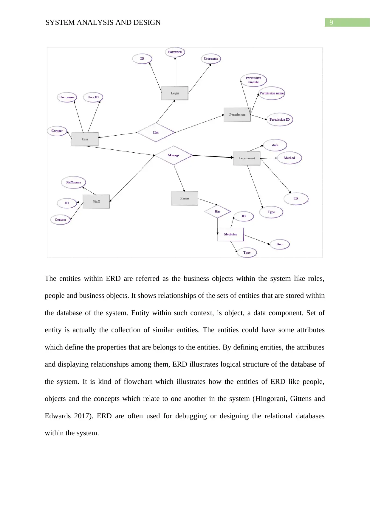
The entities within ERD are referred as the business objects within the system like roles,
people and business objects. It shows relationships of the sets of entities that are stored within
the database of the system. Entity within such context, is object, a data component. Set of
entity is actually the collection of similar entities. The entities could have some attributes
which define the properties that are belongs to the entities. By defining entities, the attributes
and displaying relationships among them, ERD illustrates logical structure of the database of
the system. It is kind of flowchart which illustrates how the entities of ERD like people,
objects and the concepts which relate to one another in the system (Hingorani, Gittens and
Edwards 2017). ERD are often used for debugging or designing the relational databases
within the system.
Paraphrase This Document
Need a fresh take? Get an instant paraphrase of this document with our AI Paraphraser
10SYSTEM ANALYSIS AND DESIGN
Domain Class Diagrams
Betty was interested in acquiring Information system for their business for handling
customer base, the order as well as their bills. Betty knew that information system had the
potential in easing the business dealings. This new emerging technology could be beneficial
also for their business (Cassidy 2016). However, Kevin remained unconvinced about benefits
of the computers. Domain Class Diagram gives an overview of system through describing
classes as well as the objects within the system as well as relationship among them. This
provides usages’ wide variety, from modelling data structure of the domain to depth design of
this system. With share model facilities, the class model could be reused in interaction
diagram to model depth design of dynamic behaviour (Stikkolorum, Ho-Quang and Chaudron
2015). Abstraction is relationship which relates set of the elements which represent similar
concepts at separate levels for abstraction and from separate viewpoints. Abstraction is
dependency where there is mapping among two elements. Element import could be defined
as directed relationship among packageable element and importing namespace. Name of
packageable element or alias is added for the namespace to import namespace. This is
possible also for controlling whether an element that is imported could be imported further.
11SYSTEM ANALYSIS AND DESIGN
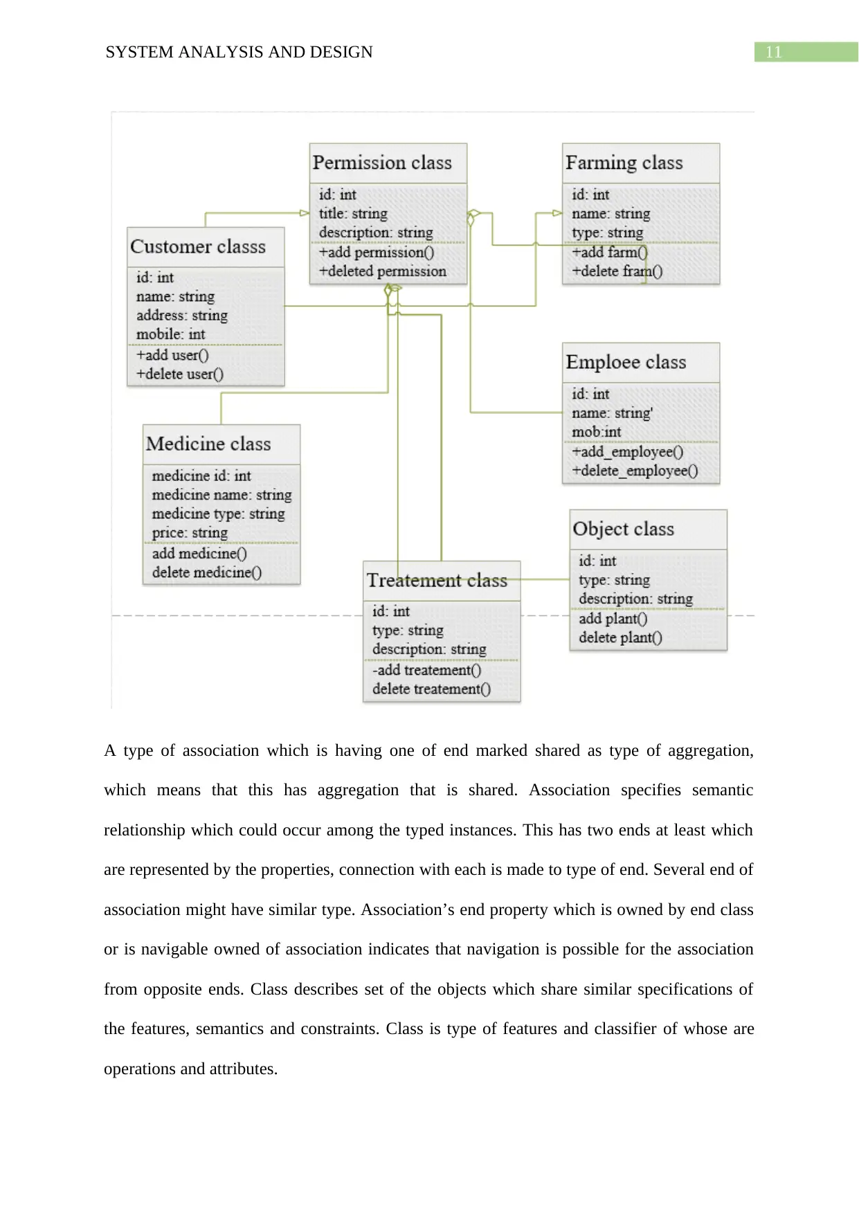
A type of association which is having one of end marked shared as type of aggregation,
which means that this has aggregation that is shared. Association specifies semantic
relationship which could occur among the typed instances. This has two ends at least which
are represented by the properties, connection with each is made to type of end. Several end of
association might have similar type. Association’s end property which is owned by end class
or is navigable owned of association indicates that navigation is possible for the association
from opposite ends. Class describes set of the objects which share similar specifications of
the features, semantics and constraints. Class is type of features and classifier of whose are
operations and attributes.
⊘ This is a preview!⊘
Do you want full access?
Subscribe today to unlock all pages.
Trusted by 1+ million students worldwide
1 out of 20
Related Documents


Your All-in-One AI-Powered Toolkit for Academic Success.
+13062052269
info@desklib.com
Available 24*7 on WhatsApp / Email
![[object Object]](/_next/static/media/star-bottom.7253800d.svg)
Unlock your academic potential
Copyright © 2020–2026 A2Z Services. All Rights Reserved. Developed and managed by ZUCOL.